MITECH QUAD User manual

QUAD
BARRIERA ALL’INFRAROSSO ATTIVO A QUATTRO LENTI
Portata massima 200 m –Portata minima 100 m
Istruzioni di uso ed installazione
CARATTERISTICHE TECNICHE E CONSUMI
Portata massima: 200 m - Portata minima: 100 m
Frequenze digitali selezionabili 8
Sincronizzazione ottica
Allineamento con mirino e segnalazione a LED
Angolo di rilevazione verticale 20°, orizzontale 180°
Temperatura di funzionamento da -25°C a +55°C
Disqualifica incorporata
Buzzer di allarme e di stato in fase di programmazione
Tempo di risposta regolabile tra 50 e 240m/sec.
Alimentazione da 13.8 a 24 Vdc
Assorbimento massimo 100 mA
Tensione minima di funzionamento (livello segnale) da 1,8 a 2,0 Volt
Dimensioni 310x95x95 cm
Grado di protezione IP55
Funzionamento disqualifica:
quando la potenza del segnale diminuisce lentamente fino a 0,8 V il rilevatore attiva
l'allarme anti-flog (uscita fault), quando il segnale scende a 0,4 V, allarme attivo.
MADE IN ITALY QUAD - Rev. 3 - 06/2020- MITECH®srl si riservadi modificarei dati senza preavviso. Pagina 1 di 2
QUAD è la mini barriera all’infrarosso attivo a quattro lenti dalle dimensioni molto contenute. Precablata e pronta per l’installazione
è composta da un’unità trasmittente ed una ricevente con 8 frequenze digitali selezionabili.
DESCRIZIONE MORSETTIERA E DIP SWITCH RICEVITORE
DESCRIZIONE MORSETTIERA E DIP SWITCH TRASMETTITORE
10 9 8 7 6 5 4 3 2(-) 1(+) 1 2 3 4 5 6 7 8 9 10
ON
1 2 3 4 5 6 7 8 9 10
ON
1 –2: alimentazione 13,8 / 24 Vdc
3 –4: uscita allarme NC o NO
5 –6: uscita disqualifica (fault) NC
7 –8: uscita tamper NC
1 –2 –3: impostazione frequenza
4 –5 –6: non utilizzati
7 –8: selezione funzione (vedere TABELLA FUNZIONI a PAG.2)
9: ON/OFF cicalino
10: settaggio uscita allarme ON = NO –OFF = NC
MORSETTIERA DIP SWITCH
MORSETTIERA DIP SWITCH
1 –2: alimentazione 13,8 / 24 Vdc
3 –4 –5 –6 –9 –10: non utilizzati
8 –7: uscita tamper NC
1 –2 –3: impostazione frequenza
4 –5 –6 –9 –10: non utilizzati
7 –8: selezione funzione (vedere TABELLA FUNZIONI a PAG.2)
10 9 8 7 6 5 4 3 2(-) 1(+)
TAMPER POWER
TAMPER FAULT ALLARM POWER
MITECH®srl
Uffici:
Via Roncaglia, 14
20146 Milano –Italia
Produzione:
Via Ramazzone, 23
43010 Fontevivo (PR) –Italia
Tel.: +39 02.48006383
Fax: +39 02.48025620
tech@mitech-security.com
www.mitech-security.com
MADE IN ITALY QUAD - Rev. 3 - 06/2020- MITECH®srl si riservadi modificarei dati senza preavviso. Pagina 2 di 2
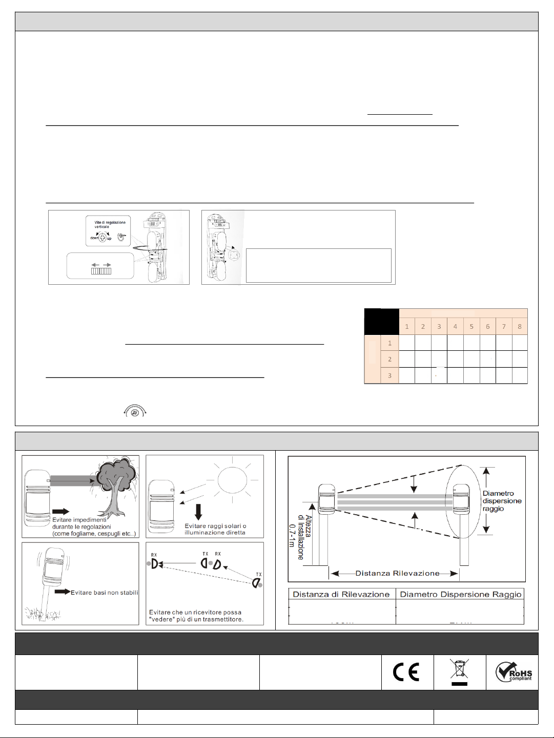
NOTE PER L’INSTALLAZIONE
200 m 3,2 m
120 mm
120 mm
INSTALLAZIONE - ALLINEAMENTO - CAMBIO FREQUENZA - REGOLAZIONE DELLA SENSIBILITA’
1.
2.
1.
2.
3.
1.
2.
INSTALLAZIONE
Fissare le barriere in modo che siano in asse e cablare la morsettiera.
Sia sul ricevitore (RX) che sul trasmettitore (TX) verificare che tutti i dip switch siano posizionati in OFF ed alimentare i moduli.
ALLINEAMENTO (CONTROLLO LIVELLO SEGNALE)
Controllare il led rosso sul modulo ricevente, se è spento ed il cicalino non suona (per abilitare il cicalino posizionare
il dip switch 9 in ON) le barriere sono allineate. Se il led è acceso ed il cicalino suona, seguire la seguente procedura:
Sul ricevitore posizionare in ON il dip switch 8 e di seguito in ON anche il dip switch 7, NON VICEVERSA.
Nota: questa è la procedura da seguire anche se a moduli allineati si vuole solo controllare il livello segnale.
Sul display verrà visualizzato un valore di segnale, orientare quindi il gruppo ottico del ricevitore nella direzione del trasmettitore
e viceversa fino a quando il led sul modulo ricevente sarà spento ed il cicalino smetterà di suonare.
I valori sono da considerarsi ottimali se compresi tra 2,6 a 3,6 V, se il led si spegne anche sotto i 2,6 V significa che le barriere
stanno comunicando, se possibile però cercare di raggiungere comunque un valore compreso tra 2,6 e 3,6 V.
Per le regolazioni verticali agire sulla vite di regolazione, mentre per quelle orizzontali intervenire ruotando la staffa (vedere
IMMAGINE 1). Se necessario aiutarsi con il mirino (vedere IMMAGINE 2).
Una volta allineati i moduli posizionare in OFF il dip switch 8 e di seguito in OFF il dip switch 7, NON VICEVERSA.
CAMBIO FREQUENZA
Per cambiare la frequenza che di default è su 1 (dip switch 1,2 e 3 in OFF),
seguire la seguente procedura:
Prima sul modulo RX e poi sul modulo TX, utilizzando i dip switch 1, 2 e 3,
settare la frequenza, vedere tabella a lato per le 8 combinazioni possibili.
Prima sul modulo RX e poi sul modulo TX confermare la frequenza posizionando
in ON il dip switch 7 e dopo un secondo riposizionandolo in OFF.
ATTENZIONE: NON LASCIARE MAI IL DIP SWITCH 7 IN ON.
REGOLAZIONE DELLA SENSIBILITA’
Ruotare il trimmer posizionato su lato destro del ricevitore, per regolare la sensibilità.
OFF ON OFF ON OFF ON OFF ON
OFF OFF ON ON OFF OFF ON ON
OFF OFF OFF OFF ON ON ON ON
NUMERO FREQUENZA (DA 1 A 8)
DIP
1
2
3
1 2 3 4 5 6 7 8
MINMAX
PUNTO DI OSSERVAZIONE DEL MIRINO:
porsi ad almeno 5 cm di distanza dal foro
che è presente sia sull’RX che sul TX
IMMAGINE 2
IMMAGINE 1
REGOLAZIONE ORIZZONTALE
SINISTRA DESTRA

QUAD
ACTIVE INFRARED BARRIER WITH FOUR LENS
Maximum range 200 m –Minimum range 100 m
Installation and user manual
GENERAL FEATURES AND ABSORPTION
Maximum range 200 m –Minimum range 100 m
8 digital frequencies
Optical synchronization
Aligning with the viewfinder and LED signal
Vertical angle 20 °, horizontal 180 °
Operating temperature from -25 ° C to + 55 ° C
Disqualification system
Buzzer alarm and status during programming
Response time adjustable between 50 and 240 m / sec.
Power supply 13.8 –24 Vdc
Maximum absorption 100 mA
Minimum operating voltage (signal level) from 1.8 to 2.0 volts
Dimensions 310x95x95 cm
Protection class IP55 (IP65 with box TOWER GARDEN)
Anti-flog function:
Where signal strenght decrease slowly to 0,8 V the detector will active anti-flog alarm
(fault output), when signal decrease ti 0,4 V, will active alarm.
MADE IN ITALY QUAD - Rev. 03 - 06/2020 - MITECH® srl reservesthe rightto change the informationin this document without warning Page 1 of 2
QUAD is the mini active infrared barrier with and small dimensions. Ready for installation it consists of a transmitter and a receiver
with 8 digital frequencies selectable.
DESCRIPTION OF CLAMP AND DIP SWITCH RECEIVER
DESCRIPTION OF CLAMP AND DIP SWITCH TRANSMITTER
10 9 8 7 6 5 4 3 2(-) 1(+) 1 2 3 4 5 6 7 8 9 10
ON
1 2 3 4 5 6 7 8 9 10
ON
1 –2: 13,8 / 24 Vdc
3 –4: alarm output NC o NO
5 –6: fault output NC o NO
7 –8: tamper output NC
1 –2 –3: setting frequency
4 –5 –6: not used
7 –8: function selection (see table 2)
9: ON/OFF buzzer
10: alarm output setting ON = NO - OFF = NC
CLAMP DIP SWITCH
CLAMP DIP SWITCH
1 –2: 13,8 / 24 Vdc
3 –4 –5 –6 –9 –10: not used
8 –7: tamper output NC
1 –2 –3: setting frequency
4 –5 –6 –9 –10: not used
7 –8: function selection (see table 2)
10 9 8 7 6 5 4 3 2(-) 1(+)
TAMPER POWER
TAMPER FAULT ALLARM POWER

MITECH®srl
Offices:
Via Roncaglia, 14
20146 Milano –Italia
Production:
Via Ramazzone, 23
43010 Fontevivo (PR) –Italia
Phone: +39 02.48006383
Fax: +39 02.48025620
tech@mitech-security.com
www.mitech-security.com
MADE IN ITALY QUAD - Rev. 03 - 06/2020 - MITECH®srl reservesthe rightto change the informationin this documentwithout warning Page 2 of 2
NOTES FOR INSTALLATION
AVOID IMPEDIMENTS AVOID DIRECT SUNLIGHT
AVOID
INSTALLABLE
SURFACE AVOID THAT A RECEIVER CAN
SEE MORE TRANSMITTERS
DISTANCE OF DETECTION
RAY
DISPERSION
DIAMETER
EXAMPLE
OF INSTALLATION HEIGHT
200 m 3,2 m
DISTANCE OF DETECTION RAY DISPERSION DIAMETER
INSTALLATION - ALIGNMENT - FREQUENCY CHANGE - SENSITIVITY ADJUSTMENT
1.
2.
1.
2.
3.
1.
2.
INSTALLATION
Fix the barriers so that they are aligned and wire the terminal block.
Both on the receiver (RX) and on the transmitter (TX) check that all the dip switches are in the OFF position and power the
modules.
ALIGNMENT (SIGNAL LEVEL CONTROL)
Control the red LED on the receiver module, if it is off and the buzzer does not sound (to enable the buzzer, set dip switch 9 to
ON) the barriers are aligned. If the LED is on and the buzzer sounds, follow the procedure below:
On the receiver, set dip switch 8 to ON and then dip switch 7 to ON, NOT BEFORE 7 AND THEN 8.
Note: this is the procedure to follow even if you only want to check the signal level with aligned modules.
A signal value will be shown on the display, then orient the receiver's optical unit in the direction of the transmitter and vice
versa until the LED on the receiver module is off and the buzzer stops ringing.
The values are to be considered optimal if included between 2.6 to 3.6 V, if the LED goes off even below 2.6 V it means that the
barriers are communicating, if possible, however, try to reach a value between 2 anyway, 6 and 3.6 V.
For vertical adjustments, act on the adjustment screw, while for horizontal adjustments, rotate the bracket (see IMAGE 1). If
necessary, use the viewfinder to help you (see IMAGE 2).
Once the modules are aligned, set dip switch 8 to OFF and dip switch 7 to OFF, NOT BEFORE 7 AND THEN 8.
FREQUENCY CHANGE:
To change the frequency which by default is 1 (dip switches 1,2 and 3 in OFF),
follow the procedure below:
First on the RX module and then on the TX module, using the dip switches 1,2 and 3
set the frequency, see the table on the side for the 8 possible combinations.
First on the RX module and then on the TX module confirm the frequency
by setting dip switch 7 to ON and after a second repositioning it in OFF.
ATTENTION: NEVER LEAVE DIP SWITCH 7 ON.
SENSITIVITY ADJUSTMENT:
Turn the trimmer located on the right side of the receiver to adjust the sensitivity.
OFF ON OFF ON OFF ON OFF ON
OFF OFF ON ON OFF OFF ON ON
OFF OFF OFF OFF ON ON ON ON
FREQUENCY NUMBER (FROM 1 TO 8)
DIP
1
2
3
1 2 3 4 5 6 7 8
MINMAX
VIEWFINDER POINT OF VIEW
IMAGE 2
IMAGE 1
ADJUSTABLE BRACKET
LEFT RIGHT
Adjusting sc rew
Table of contents
Languages:
Other MITECH Security System manuals


Popular Security System manuals by other brands


EDM
EDM Solution 6+6 Wireless-AE installation manual

Highway Safety Group
Highway Safety Group EA401 user manual

Siren
Siren LED GSM operating manual

Detection Systems
Detection Systems 7090i Installation and programming manual

Se-Kure Controls
Se-Kure Controls MicroMini SK-4841 instructions

Siemens
Siemens FDM273 manual