Mitel MX-ONE User manual

INSTALLATION INSTRUCTION
Installing Boards and Cabling
Catarina St encstenGöran Lanner grenglannerg renGlobenMitelR&D MX-ONE & CMG

21/1531-ASP11301 Uen B3 2016-02-17 2
NOTICE
The information contained in this document is believed to be accurate in all respects
but is not warranted by Mitel Networks™ Corporation (MITEL®). Mitel makes no
warranty of any kind with regards to this material, including, but not limited to, the
implied warranties of merchantability and fitness for a particular purpose. The informa-
tion is subject to change without notice and should not be construed in any way as a
commitment by Mitel or any of its affiliates or subsidiaries. Mitel and its affiliates and
subsidiaries assume no responsibility for any errors or omissions in this document.
Revisions of this document or new editions of it may be issued to incorporate such
changes.
No part of this document can be reproduced or transmitted in any form or by any means
- electronic or mechanical - for any purpose without written permission from Mitel
Networks Corporation.
Trademarks
Mitel® is a registered trademark of Mitel Networks Corporation.
All trademarks mentioned in this document are the property of their respective owners,
including Mitel Networks Corporation. All rights reserved.
®, TM Trademark of Mitel Networks Corporation
©Copyright 2016, Mitel Networks Corporation
All rights reserved

INSTALLING BOARDS AND CABLING
321/1531-ASP11301 Uen B3 2016-02-17
1 INTRODUCTION
MX-ONE is a communication solution for enterprises. MX-ONE integrates voice
communication in fixed and mobile networks for public as well as private service.
MX-ONE can be integrated into an existing Local Area Network (LAN) infrastructure.
MX-ONE supports both IP telephony and functions found in classic circuit-switched
PBXes (Private Branch Exchanges).
1.1 SCOPE
This document describes the MX-ONE cabling and connection in a detailed way. It is
aimed for customers doing new installation. For other parts of the Installation see:
•Installation preparation and Earthing, 19/1531-ASP11301
•Installation Chassis in a Cabinet, 20/1531-ASP11301
1.2 TARGET GROUP
The target group for this document is personnel involved in installing the MX-ONE.
1.3 PREREQUISITES
This section lists requirements that must be fulfilled before the installation starts.
1.3.1 ELECTRICAL CONNECTIONS
Installation procedures involving connection of power cables, batteries and earthing
must be performed according to local regulations.
1.3.2 SAFETY
All personnel involved in installation must read and understand the safety instructions
prior to installation, see the description document for SAFETY.

21/1531-ASP11301 Uen B3 2016-02-17 4
INSTALLING BOARDS
2 INSTALLING BOARDS
Device boards can, in the 7U chassis only be placed in the board positions 01-29 and
45-73. Not in positions 33, 37 and 41.
Note: It is important to firmly insert the boards, to avoid bending any back plane
connectors, or it’s contact pins. Press evenly on both sides of the front. Do NOT
use the extractor (available in some boards) to press the board in.Only for the
final millimeter of sliding in the board, the extractor is allowed to be used.
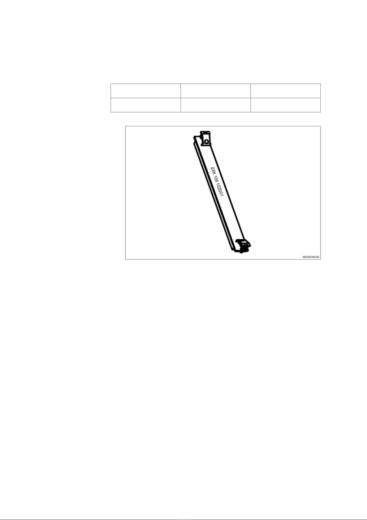
To remove any board, use the extractor, or use the tool LTD 11702 and 12 in any avail-
able keyhole in the fronts.
Table 1 Boards in MX-ONE
Board Product
number
Building
height
Time
Slots
used
Remarks
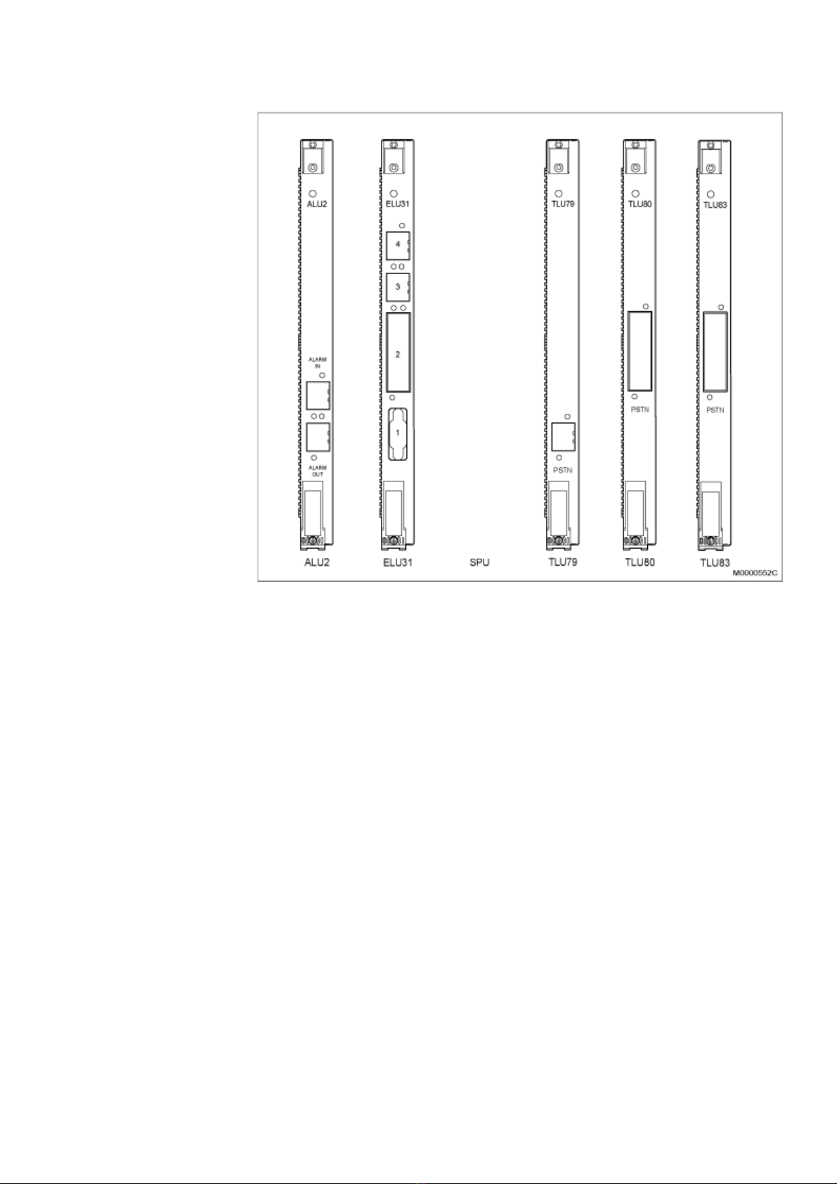
ALU2 ROF 137 5373/11 20mm 8 Alarm unit for external alarms
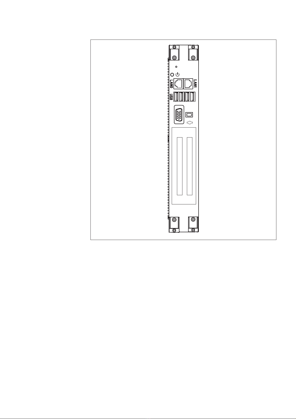
ASU ROF 137 6307/1x 40mm --- Mitel Server Unit. 8GM. For more
information see item below.
ASU Lite ROF 137 6307/3x 40mm --- Mitel Server Unit, Lite. 4 GB. For more
information see item below.
ASU-II ROF 137 6307/4 40mm --- Mitel Server Unit. 16GB. For more
information see item below.
DC/DC ROF 137 6303/1 40mm --- Power unit for 7U chassis
ELU26 ROF 137 5321/12 20mm 8 ISDN-S digital extensions
ELU31 ROF 137 5412/4* 20mm 32 DECT extensions
ELU33 ROF 137 5062/1 20mm 32 Digital extensions
ELU34 ROF 137 5064/x 20mm 32 Analog extensions with message waiting
FTU2 ROF 137 5415/11 20mm 8 Failure Transfer Unit
MFU ROF 137 5348/X 20mm 8 Multi frequency unit
MGU ROF 137 6304/X 40mm --- Media Gateway Unit. For more
information see item below.
MGU2 ROF 137 6304/4 20mm --- Media Gateway Unit. For more
information see item below.
TLU76 ROF 137 5338/x* 20mm 32 Digital trunk, ISDN, E1, DPNSS, CAS,
SS7
TLU77 ROF 137 5387/x* 20mm 23 ISDN, T1, DPNSS, CAS depending on
version
TLU79 ROF 137 5349/11* 20mm 8 ISDN-T 2B+D trunk line
TLU80 ROF 137 5406/11 20mm 8 4-wire analog trunk using E&M signaling.
This board can only be used in MX-ONE
Classic. Not in MX-ONE Lite or 1U
TLU83 ROF 137 6305/1 20mm 8/12 Analog trunk line (loop start, ground start.
CLI with FSK and DTMF)
TLU83 ROF 137 6305/2 20mm 8/12 Analog trunk line (loop start, ground start,
call metering. CLI with FSK and DTMF)

INSTALLING BOARDS AND CABLING
521/1531-ASP11301 Uen B3 2016-02-17
Note: Secure all boards with the screws located in the extractor. Use screw driver with
Torx T8.
2.1 ASU, ASU-II AND ASU LITE
The ASU’s has a disk bay for 2 separate HDD (Hard disk drives) or SSD (Solid state
drives). They are located behind a cover in the front.
Note: SW RAID 1 is supported on Mitel ASU and ASU-II.
Close to the LED near the LAN-ports, there is a hole for performing reset/ software
shout down.
The ASU’s has a battery for real time clock. This battery is located just behind the board
for the SATA drives connection.
Note: Due to the high weight of these boards, handle them with care, and hold the
board only in the front. Also, be careful when inserting it into the subrack. Do not
force it to avoid any bending of the board.
2.2 MGU AND MGU2
The MGU board has a 40mm front when used in MX-ONE Classic, MX-ONE Lite, and
in MX-ONE 1U chassis.
The MGU2 board has a 20mm front and can be used in any chassis.
Close to the LED there is a hole for performing reset.
For more info see description, Media Gateway Unit, MGU, 1/1551-ANF90136.
2.3 EMPTY BOARD POSITIONS
If any empty positions are left in a chassis after mounting all boards, these empty slots
have to be filled with Dummy-fronts to fulfill the EMC demands. See 2.4 Dummy Front
on page 5.
2.4 DUMMY FRONT
This section describes the dummy front in 19" cabinets.
Dummy fronts are installed at all empty positions in the 19" submags. New boards can
be installed at these positions. Remove the dummy front at the position were the new
board is to be installed and insert the new board.
TLU83 ROF 137 6305/3 20mm 8/12 Analog trunk line (loop start, ground start,
CLI with DTMF)
TMU ROF 137 5335/x 20mm 32 Tone and Multi part Unit. DTMF
Board Product
number
Building
height
Time
Slots
used
Remarks

21/1531-ASP11301 Uen B3 2016-02-17 6
INSTALLING BOARDS
Note: All empty board positions must be covered with dummy fronts to fulfill the EMC
requirement and to be compliant with the BYB501 cooling requirements (air
flow).
Table 2 Dummy Front
Figure 1: 20mm Dummy Front
2.5 CONNECTORS AND LEDS ON BOARD FRONTS
This section describes the connectors and LEDs on the boards.
The indication of board status with dual color LED is:
• Steady RED: The board is in passive state
• Flashing RED: Error state
• Alternating RED/GREEN: The board is starting up or is blocked.
• Steady GREEN: The board is active.
• Flashing GREEN: The board is active and is signaling.
Note: DC/DC-, MGU-, TLU77- and ASU-boards deviate from above. See the figures
below regarding how they differ.
Function Product Number
Front 20 mm SXK 106 1020/01

INSTALLING BOARDS AND CABLING
721/1531-ASP11301 Uen B3 2016-02-17
Figure 2: TLU77, TMU, TLU76, ELU33, and ELU34 Board Fronts

21/1531-ASP11301 Uen B3 2016-02-17 8
INSTALLING BOARDS
Figure 3: ASU Front Connectors
The SATA disks are located behind a cover. Two disks are used for RAID-1.
M0001172A
ASU-E
SATA 0
SATA 1 1
0
Connector no: 1
Connector no: 2
LED:
Green
Connector no: 3
15 pole
female D-sub
2 RJ 45 ports
4 USB Ports

INSTALLING BOARDS AND CABLING
921/1531-ASP11301 Uen B3 2016-02-17
Figure 4: DC/DC Front Connectors and LEDs
DC/DC
FAN UNIT
ALARM IN
-48V
INPUT

21/1531-ASP11301 Uen B3 2016-02-17 10
INSTALLING BOARDS
Figure 5: ALU2, ELU31, TLU79, TLU80 and TLU83 Fronts
Note: ELU26 has the same front view as TLU79.

INSTALLING BOARDS AND CABLING
11 21/1531-ASP11301 Uen B3 2016-02-17
Figure 6: TLU77 Front Connectors and LEDs

21/1531-ASP11301 Uen B3 2016-02-17 12
INSTALLING BOARDS
Figure 7: MGU Front Connectors with 40mm front
Figure 8: MGU2 with 20mm front
Status LED:
Green
Red
Green flashing
Red flashing
See the MGU
description for
details.
E1/T1
USB
MGU
RESET button Status LED (Green, Red, Green flashing, Red flashing)
LAN connections
USB connection
E1/T1 connections
Reset LAN1 LAN0 1234
(behind front)
Key hole
See the MGU2 description for details.

INSTALLING BOARDS AND CABLING
13 21/1531-ASP11301 Uen B3 2016-02-17
3 CABLING
Cabling involves both internal and external connections on site.
External cabling is the routing of cables for grounding, to power equipment and other
external devices. Internal cabling is the routing of cables within a cabinet or between
cabinets.
Use the fastener straps (cable tie) provided in material set 25/BYB 501/1 to fasten the
cables to the rack, cable chutes, rear sides of chassis and so on. See Table 5 Set of
Cable holders (Cable tie) on page 20.
Table 3 Cables in MX-ONE
Unit Cable Product Number Remarks
ALU2 TSR 491 0306/20M to MDF
ASU, ASU-II and
ASU Lite
61L00002AAA-A to LAN 1GBit, RJ45-RJ45, straight. L=2,4
meters
TSR 482 0211/2400 to LAN, 100Kbit, RJ45-RJ45, straight. L=2,4
meters
TRS 899 135/1 USB to V.24 adapter cable
Battery, std 61L00006AAA-A to AC/DC. (included in cable kit for 1U power
87L00036AAA-A. For 2U the cable is included
in the unit)
Battery, UK TSR 903 0113/1 to AC/DC only for UK
Battery TFL281325/4000 Between batteries for parallel connection
DC/DC TSR 903 021/5000, /12M to 1U or 2U AC/DC
TSR 490 0116/5000, /12M to 1U or 2U AC/DC for the UK
ELU26 TSR 491 414/32M to MDF
ELU31, ELU33,
ELU34
TSR 910 1054/16M, 32M to MDF
ELU31 TSR 901 1226/3000, /5000, /15M Sync-ring
FTU2 TSR 910 1059/32M to MDF
MFU/11 TSR 491 0306/20M to MDF
MGU and MGU2 TSR 482 0211/2400, /20M to LAN 100Kbit or E1/T1 to E1/T1
TSR 899 135/1 USB to V.24 adapter cable
TSR 482 0240/7000 for E1/T1 crossover
61L00002AAA-A to LAN 1GBit, RJ45-RJ45, straight. L=2,4
meters
TLU76 TSR 482 0211/2400, /20M to MDF
TLU77 TSR 482 0211/2400, /20M to MDF
TLU79 TSR 491 414/32M to MDF
TLU80 TSR 910 1054/16M, /32M to MDF
TLU83 TSR 910 1054/16M, /32M to MDF
TMU/12 TSR 491 0306/20M to MDF
MX-ONE Lite 3U
chassis,
87L00039 xAA-A
TSR9020279/2000 to AC/DC, 48V
61L00007AAA-A for Alarm connection

21/1531-ASP11301 Uen B3 2016-02-17 14
CABLING
*) Fan BFD50908
Note: Consider the needed cabling for network or server redundancy. For more infor-
mation, see the description for MIVOICE MX-ONE, chapter REDUNDANCY.
3.1 CONNECTOR POSITIONS
Only boards with EMC shielded fronts are used in the MX-ONE subracks.
3.1.1 CONNECTOR NUMBERING
The connector positions are marked in numerical order starting from 1 for the lowest
connector position, 2 for the position above it and so on, see Figure 9: Connectors
positioning on page 15.
MX-ONE 1U
chassis,
87L00032xAA-A
TSR9020279/2000 to AC/DC, 48V
Network TSR 482 0211/20M LAN, 100KBit. RJ45 - RJ45, straight. L=20
meters
61L00002BAA-A LAN, 1GBit, RJ45 - RJ45, straight.
L= 20 meters
Power to Fan*) TSR 903 021/5000, /12M,
TSR 490 0116/5000, /12M for UK
to AC/DC, 48V
Fan *) to alarm TSR 902 0274/2200
TSR 902 0277/2000
SXK 106 2097/1
Alarm cables and plug
Unit Cable Product Number Remarks

INSTALLING BOARDS AND CABLING
15 21/1531-ASP11301 Uen B3 2016-02-17
Figure 9: Connectors positioning

21/1531-ASP11301 Uen B3 2016-02-17 16
CABLING
3.2 CABLE LABELING
3.2.1 PRODUCT LABELING
3.2.1.1 Previous Type of Labeling
Each cable has a product number as follows:
a = Cable type
b = Cable length in mm
3.2.1.2 Existing Type of Labeling
If the cable is long, the length can be marked in meter (M) as follows:
a = Cable type
b = Cable length in meter. /16M = 16 meters
3.2.2 LABEL SETS
Every MX-ONE Service Node has a label set with labels that are used to mark the
cables in the MX-ONE. See Table 4 on page 16
Table 4
3.2.3 LABELING OF CABLES
Note: To mark source and destination for the cable, always put a label on each cable
end.
Cables are marked with labels in both ends. The labels contain the following informa-
tion:
• Cable source
• Cable destination
Product Number Server
Number
Product Number Server Number
SVH 277 030/1 1 SVH 277 030/5 6-10
SVH 277 030/2 2 SVH 277 030/6 11-20
SVH 277 030/3 3 SVH 277 030/7 21-40
SVH 277 030/4 4-5 SVH 277 030/8 > 40 (one for
each Server)

INSTALLING BOARDS AND CABLING
17 21/1531-ASP11301 Uen B3 2016-02-17
• Server number
• Cable number
• Position (in boards or other devices) for cable connection
For a general explanation of the information in cable labels, see Figure 10: Labeling
Cables on page 17.
Figure 10: Labeling Cables
3.2.4 LABELING OF INTERNAL CABLES
The internal cables connected to fixed positions in the exchange are already labeled at
delivery. The label indicates the position of the cable's own connector as well as that of
the other end.
For example: GW1/81 (0*21*4) means that for Gateway 1, cable 81 is to be placed on
the left side of MGU (0= left, 1= right), board position 21 (01, 05, 09,..., 77), and at
connector 4, counted from the bottom, see Figure 11: Labeling of cables on page 18.

21/1531-ASP11301 Uen B3 2016-02-17 18
CABLING
Figure 11: Labeling of cables
3.3 CONNECTING INTERNAL POWER CABLES
For instructions on how to connect mains cable to the AC/DC unit, refer to manufac-
turer instructions supplied with the unit.
Refer to local regulations when working with electric power.
3.3.1 CONNECTING THE BATTERIES TO THE AC/DC UNIT
Work involving batteries must be carried out by persons with appropriate technical
training and experience necessary to be aware of hazards to which they can be
exposed.
The battery fuse/circuit breaker is located in the power supply unit. It means that the
conductor connected to the negative pole of the battery and to the battery fuse/circuit
breaker is an unfused battery conductor.
It is extremely hazardous to work with unfused battery conductors.
Note: Before battery conductors are connected, disconnected, or installed, remove the
conductor to the negative pole (A) or remove an interconnection bridge (B), see
Figure 12: Example of Removing the Negative Battery Conductor (A) and an
Interconnecting Bridge (B) on page 18.

INSTALLING BOARDS AND CABLING
19 21/1531-ASP11301 Uen B3 2016-02-17
Figure 12: Example of Removing the Negative Battery Conductor (A) and an
Interconnecting Bridge (B)
Figure 13: Connecting the Batteries
General battery connection:
1. Connect the cable lug (L) of the grey cable supplied with the batteries mounting
set (BKB 201 003/1) to the red plus pole (D) of the rightmost battery block, see
Figure 13: Connecting the Batteries on page 19.
2. Fasten the screw (B) to secure the cable lug and press down the cover (I) on the
red plus pole (D).
3. Connect the grey positive (+0V) DC supply cable (L) to the positive bus
bar/connector according suppliers documentation. For connection in BZA10911,
the 2U AC/DC, see document BCG.00075 for User manual, and
1/1531-BZA10911 for Quick Install Guide.
4. Connect the cable lug (M) of the black cable to the minus pole (D) of the leftmost
battery block, see Figure 13: Connecting the Batteries on page 19.
5. Fasten the screw (B) to secure the cable lug and press down the cover (I) on the
black minus pole (D).
6. Connect the black negative (-48V) DC supply cable (M) to the appropriate nega-
tive DC connection on the AC/DC-unit. For connection in BZA10911, the 2U
AC/DC see document BCG.00075 for User manual, and 1/1531-BZA10911.
Battery connection for the UK:
1. Connect the cable lug (L) of the blue cable part of the TSR 903 0113/1 cable to
the red plus pole (D) of the rightmost battery block, see Figure 13: Connecting
the Batteries on page 19.
2. Fasten the screw (B) to secure the cable lug and press down the cover (I) on the
red plus pole (D).

21/1531-ASP11301 Uen B3 2016-02-17 20
CABLING
3. Connect the blue positive (+0V) DC supply cable (L) to the positive bus
bar/connector according suppliers documentation. For connection in BZA10911,
the 2U AC/DC, see document BCG.00075 for User manual, and
1/1531-BZA10911.
4. Connect the cable lug (M) of the grey cable part to the minus pole (D) of the left-
most battery block, see Figure 13: Connecting the Batteries on page 19.
5. Fasten the screw (B) to secure the cable lug and press down the cover (I) on the
black minus pole (D).
6. Connect the grey negative (-48V) DC supply cable (M) to the appropriate nega-
tive DC connection on the AC/DC-unit. For connection in BZA10911, the 2U
AC/DC see document BCG.00075 for User manual, and 1/1531-BZA10911 for
Quick Install Guide.
3.3.2 CONNECTING THE AC/DC UNIT TO THE MIVOICE MX-ONE
See suppliers documentation for correct connection to the AC/DC.
When connecting cables in the AC/DC unit, always fasten nearby cables to each others
and to any cable cloth or frame using fastener straps included in the 25/BYB 501/1.
This to relieve the force on the connections.
Table 5 Set of Cable holders (Cable tie)
Note: Do not cut the cables. The shortest length of the cables from the AC/DC unit to
the DC/DC board must be 5 meters.
Note: For the UK market the cable TSR 490 0116 is used. Also note that the blue cable
is positive (+0V) and the grey cable is negative (-48V) for the UK.
3.3.2.1 Connecting BZA10911, the 2U Power unit
See suppliers document BCG.00075 for User manual, and 1/1531-BZA10911 for
Quick Install Guide, stored in CPI.
3.3.2.2 Connecting 87L00034AAA-A, the 1U Power unit
See suppliers document BCG 00031.44 for Supplier User manual, and document BCG
00133 for Quick Install Guide, stored in CPI.
3.3.3 CONNECTING AC/DC TO THE LAN
The BZA 10911 units can be equipped with a communication module. The units
communicate via the LAN. For details about functionality and configuration, see
suppliers data sheet.
25/BYB 501/1 Set for cables
Title/Function Product Number Quantity
HOLDER FOR STRAP SXA 123 0411/2 40
CABLE CLAMP (STRAP) SET 103 02 40
Other manuals for MX-ONE
2
Table of contents