Mitel T941AM8 User manual

T941AM8 ALARM MODULE
INSTALLATION GUIDE

58/1531-ANF 901 43 Uen E1 2016-03-18
NOTICE
The information contained in this document is believed to be accurate in all respects but is not
warranted by Mitel Networks™ Corporation (MITEL®). Mitel makes no warranty of any kind with
regards to this material, including, but not limited to, the implied warranties of merchantability and
fitness for a particular purpose. The information is subject to change without notice and should not
be construed in any way as a commitment by Mitel or any of its affiliates or subsidiaries. Mitel and its
affiliates and subsidiaries assume no responsibility for any errors or omissions in this document.
Revisions of this document or new editions of it may be issued to incorporate such changes.
No part of this document can be reproduced or transmitted in any form or by any means - electronic
or mechanical - for any purpose without written permission from Mitel Networks Corporation.
TRADEMARKS
The trademarks, service marks, logos and graphics (collectively "Trademarks") appearing on Mitel's
Internet sites or in its publications are registered and unregistered trademarks of Mitel Networks
Corporation (MNC) or its subsidiaries (collectively "Mitel") or others. Use of the Trademarks is prohib-
ited without the express consent from Mitel. Please contact our legal department at legal@mitel.com
for additional information. For a list of the worldwide Mitel Networks Corporation registered trade-
marks, please refer to the website: http://www.mitel.com/trademarks.
© Copyright 2016, Mitel Networks Corporation
All rights reserved

58/1531-ANF 901 43 Uen E1 2016-03-18
T941AM8 ALARM MODULE - INSTALLATION GUIDE
2
1 INTRODUCTION
T941AM8 has 8 physical inputs for connection to external alarm devices. Inputs are
galvanically isolated, have transient protection, and can be programmed for making or
breaking contacts.
Figure 1. The Alarm Module.
Supply voltage: 12.5 V DC ± 10%
Current consumption: max 150 mA + 100 mA for all inputs
For selection of input connection, see 7 Connection of
Alarm Inputs for Voltage-Free Make/Break.
Delivery includes: T941AM8
Modular system bus cable
Tools, etc. required: Screwdriver
Screws for installation
Soldering iron

58/1531-ANF 901 43 Uen E1 2016-03-18
T941AM8 ALARM MODULE - INSTALLATION GUIDE
3
1.1 CIRCUIT BOARD OVERVIEW
Figure 2. The circuit board of the Alarm Module.
ICO1
ICO2
8
1
18
4
1
21
61
J05
J07
J09
J04
SWO1
SW02
S04
LEDO1
IC03
S03
J08
S06
S13
18
LEDO2
S14
S05
J01 J02
J06
J03
S01 S02
1
6
LED10
LED03
RE01

58/1531-ANF 901 43 Uen E1 2016-03-18
T941AM8 ALARM MODULE - INSTALLATION GUIDE
4
2 INSTALLATION
The alarm module should be placed in a dry environment with a temperature range of 0 to
+40°C.
The figure below shows dimensions for installing the alarm module.
Figure 3. Mounting dimensions for the Alarm Module.
Note: To facilitate service after the unit is installed, we recommend a free space
of about 50 mm above and 150 mm below the unit.
Use a screwdriver or similarto release the cover byapplying a light pressure to the two snap
catches (1) and remove the cover (2).
Figure 4. Releasing the cover of the Alarm Module.
9 9
275
56,5
188,5
65 130
112
Dimensions (H x W x D)
275 x 130 x 60 mm
2
1
1

58/1531-ANF 901 43 Uen E1 2016-03-18
T941AM8 ALARM MODULE - INSTALLATION GUIDE
5
2.1 INSTALLATION TOGETHER WITH OTHER UNITS
Figure 5. Mounting two units together.
1 Remove upper and lower covers. The lower rectangular covers are used to
fasten units to each other (1).
2 Fasten the module with three screws; see figure 3.
1
1
58/1531-ANF 901 43 Uen E1 2016-03-18
T941AM8 ALARM MODULE - INSTALLATION GUIDE
6
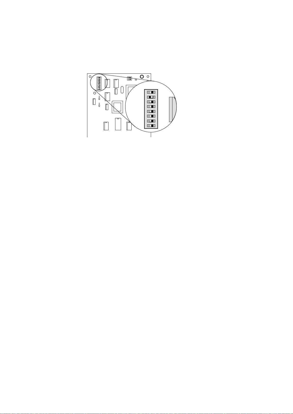
3 ADDRESSING
Select the proper address by setting address selector switch SW01. The address must not
be 00 nor the same as any other 900 unit address.
Figure 6. Addressing switch on the Alarm Module.
Note: When connected to the Central Portable Device Manager (CPDM), the
module address has to be in the range 01 to 0F.
For information about how to distribute alarms from the CPDM to the Alarm Module, see
Installation and Operation Manual, CPDM.
SW01
OFF ON
1
8

58/1531-ANF 901 43 Uen E1 2016-03-18
T941AM8 ALARM MODULE - INSTALLATION GUIDE
7
3.1 HOW TO SET THE ADDRESS
The address consists of two hexadecimal digits that are selected by the eight sections of the
address switch. The eight sections are divided into two groups, each with four sections (1-4
and 5-8). Sections 5-8 select the first (most significant) hex digit and sections 1-4 select the
second hex digit.
Figure 7. Setting the address of the Alarm Module.
1
8
2 5 6 8
ONOFF
5 6 8
switches 1 - 4,
second hex digit (D)
switches 5 - 8,
first hex digit (4)
1 3 4
2
1 3 4
7
7
1
8
4
5

58/1531-ANF 901 43 Uen E1 2016-03-18
T941AM8 ALARM MODULE - INSTALLATION GUIDE
8
4 WIRING RUNS
Theplasticpartition(shaded infigure8)is scoredtofacilitatebreakingat convenientintervals.
Figure 8. Breaking the partition for wiring.
1 Use pliers to break off a suitable section.
2 Run the wiring out through the partition.
Wiring can be run three ways from the Alarm Module:
Figure 9. How to run cables from the Alarm Module.
• Remove the rectangular pieces and run the cabling out through the side (1).
• Break off sections at short side of case and run the cabling downwards (2).
• Run the cabling through the round holes at the bottom of the case (3)
Secure the wiring with cable straps.
1 2 3 4 5 6
1
2
1
2
1
2
3
1
3

58/1531-ANF 901 43 Uen E1 2016-03-18
T941AM8 ALARM MODULE - INSTALLATION GUIDE
9
5 CONNECTION OF SYSTEM BUS
Figure 10. Connection of system bus with modular bus cable.
• Connect modular bus cabling to J01 and J02 (1)
or if required
• Connect two-wire connection to J03 screw 5 and 6 (2)
(see figure below)
Figure 11. Connection of system bus with twisted-pair and supply voltage.
Note: The data lines are polarised. Use only twisted-pairs for two-wire
connections!
1 2 3 4 5 6
1
2
1
J03
4
5 BUS 1
6 BUS 2
3
1 +12V
2 GND
Supply voltage in
Supply voltage out
System bus
Table of contents
Other Mitel Control Unit manuals


Popular Control Unit manuals by other brands

Festo
Festo Compact Performance CP-FB6-E Brief description

Elo TouchSystems
Elo TouchSystems DMS-SA19P-EXTME Quick installation guide

JS Automation
JS Automation MPC3034A user manual

JAUDT
JAUDT SW GII 6406 Series Translation of the original operating instructions

Spektrum
Spektrum Air Module System manual

BOC Edwards
BOC Edwards Q Series instruction manual

KHADAS
KHADAS BT Magic quick start

Etherma
Etherma eNEXHO-IL Assembly and operating instructions

PMFoundations
PMFoundations Attenuverter Assembly guide

GEA
GEA VARIVENT Operating instruction

Walther Systemtechnik
Walther Systemtechnik VMS-05 Assembly instructions

Altronix
Altronix LINQ8PD Installation and programming manual


