Contents | v
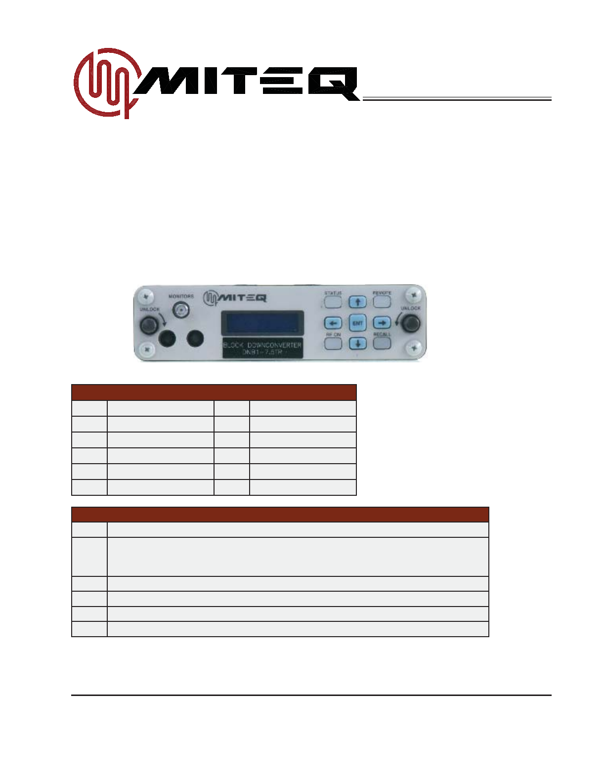
1/3 Rack Block Downconverters (Option 17)
DNB1-XTR, Rev.N, 8/14/2012
®
TABLE OF CONTENTS
SECTION 1: INTRODUCTION.............................................................................................. 1
GENERAL DESCRIPTION..............................................................................................................................................1
PHYSICAL.......................................................................................................................................................................1
MODEL NUMBERS.........................................................................................................................................................2
Converter Model Numbers.......................................................................................................................................2
EQUIPMENT CHARACTERISTICS ................................................................................................................................2
PHYSICAL.......................................................................................................................................................................2
Connector Wiring Information ..................................................................................................................................3
FUNCTIONAL .................................................................................................................................................................4
SECTION 2: INSTALLATION ................................................................................................ 6
UNPACKING, STORAGE, RESHIPMENT ......................................................................................................................6
MOUNTING.....................................................................................................................................................................6
TURN-ON PROCEDURE................................................................................................................................................6
SECTION 3: OPERATION..................................................................................................... 8
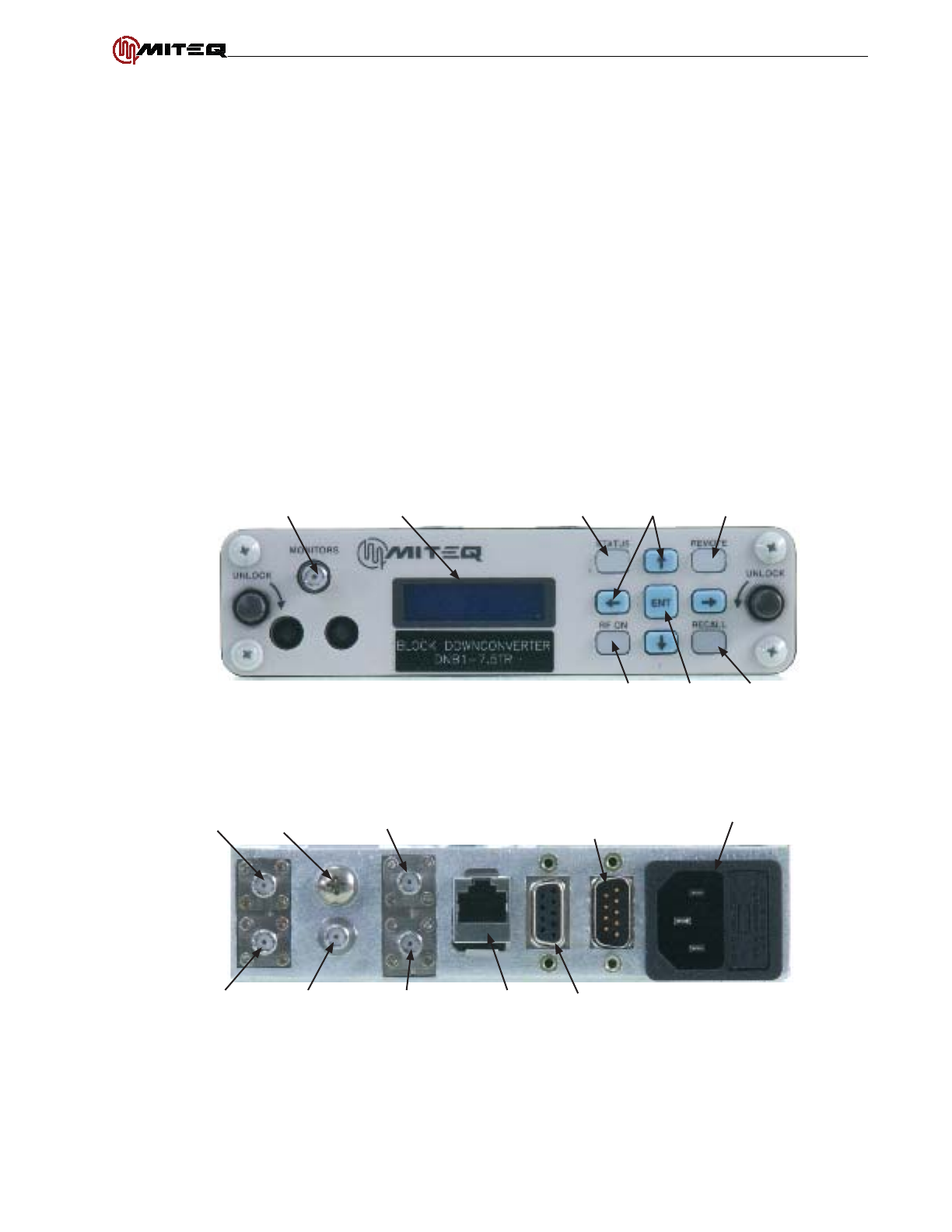
CONTROLS ....................................................................................................................................................................8
EXTERNAL CONTROLS ................................................................................................................................................8
AC Power.................................................................................................................................................................8
Fuse .........................................................................................................................................................................8
FRONT PANEL OPERATIONS .......................................................................................................................................8
INDICATOR BUTTONS...................................................................................................................................................8
SCREEN NAVIGATION AND DATA ENTRY ...................................................................................................................8
MAIN SCREEN ...............................................................................................................................................................9
ATTENUATION 2 / SLOPE SCREEN ...........................................................................................................................10
STATUS SCREEN......................................................................................................................................................... 11
SERIAL PORT REMOTE OPERATION SCREEN ........................................................................................................13
REDUNDANT SERIAL PORT REMOTE OPERATION SCREEN .................................................................................14
ETHERNET PORT REMOTE OPERATION SCREENS ...............................................................................................14
FREQUENCY REFERENCE ADJUST SCREEN..........................................................................................................17
DATE/TIME SCREEN ...................................................................................................................................................18
LCD CONTRAST/EXTERNAL FAULT SCREEN..........................................................................................................18
SERIAL PORT DESCRIPTION ..................................................................................................................................... 19
REMOTE MESSAGE PROTOCOL (RS485/RS422) ...................................................................................................19
COMMAND CODE SUMMARY.....................................................................................................................................21
COMMAND CODE DESCRIPTION ..............................................................................................................................22
ACCESSORY FAULT STATUS = AAL...........................................................................................................................22
SYSTEM FAULT STATUS = ALR .................................................................................................................................23
UNIT ATTENUATION = ATT or AT1...............................................................................................................................23
UNIT ATTENUATION WITHOUT LOG = ATN or AN1 ...................................................................................................24
UNIT ATTENUATION 2 = AT2 .......................................................................................................................................24
UNIT ATTENUATION 2 WITHOUT LOG = AN2 ............................................................................................................25
FREQUENCY BAND INFORMATION = BND (Block Converters Only)........................................................................26
FREQUENCY BAND INFORMATION WITHOUT LOG = BNN (Block Converters Only)..............................................26
FREQUENCY BAND NUMBER INFORMATION = BNM (Block Converters Only).......................................................27
UNIT COMBINATION COMMAND = COM ................................................................................................................... 28
ETHERNET PARAMETERS = EAD..............................................................................................................................29
UNIT FREQUENCY = FRQ...........................................................................................................................................29
UNIT FREQUENCY WITHOUT LOG = FRN.................................................................................................................30
FREQUENCY REFERENCE SOURCE = FRS.............................................................................................................30
IF SELECTION = IFS ....................................................................................................................................................30
UNIT EVENT LOG = LOG.............................................................................................................................................31
UNIT MEMORY REGISTER STORE/RECALL = MEM................................................................................................33
UNIT MUTE COMMAND = MUT...................................................................................................................................33
UNIT MUTE COMMAND WITHOUT LOG = MTN.........................................................................................................34
UNIT NAME = NAM.......................................................................................................................................................34