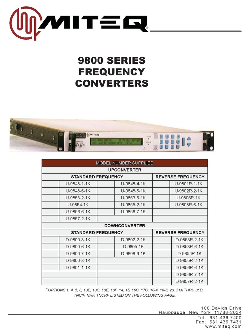
Miteq 9800 Series Specification sheet

1 00 Da vi d s Dr iv e
Ha u pp au ge , N ew Y or k 1 17 8 8-2 03 4
T e l : 6 3 1 4 3 6 7 4 0 0
F ax : 6 31 4 36 7 43 1
w ww .m iteq . co m
MITEQ TECHNICAL NOTE 25T063 NOVEMBER 2005
REV D
9800/9900 SERIES CONVERTERS LOCAL INTERFACE
AND REMOTE PROTOCOL
______________________
SECTION 1
INTRODUCTION
1.1 GENERAL DESCRIPTION
1.1.1 PHYSICAL
Figure 1-1. Front Panel
Figure 1-2. Rear Panel

2
1.2 EQUIPMENT CHARACTERISTICS
1.2.1 PHYSICAL
Chassis Dimensions
1 RU Units...................................................................................19” x 20” x 1.75” panel height
Overall Length..........................................................................................................22” maximum
Alarm Connector .................................................................................................................DE-9P
Remote Interface Connector
RS485, RS422, RS232...................................................................................................DE-9S
IEEE-488.................................................................................................IEEE-488 Receptacle
Ethernet TCP/IP ...............................................................................................................RJ45
Auxiliary Control Interface Connector
RS485, RS422 ...............................................................................................................DE-9S
Primary Power Input Connector......................................................................................... IEC320
Ground Lug........................................................................................... 10-32 screw with washers
Connector Wiring Information
Alarm Connector (J3)
Function
Pins
Normal
Fault
Summary Alarm
4,5
Open
Closed
Summary Alarm
5,6
Closed
Open
Redundancy Alarm
1,2
Open
Closed
Redundancy Alarm
2,3
Closed
Open
External Alarm Input
7,8
User defined
Remote Interface Connector (J6)
RS485 and RS422
RS232
Pin
Designation
Pin
Designation
1
Ground
2
RCV Data
3
Data Out -
3
Tx Data
5
Data In -
5
Ground
7
Data Out +
7
RTS
9
Data In +
8
CTS
Auxiliary Control Interface (J7)
RS485 and RS422
Pin
Designation
1
Ground
3
Data Out -
5
Data In -
7
Data Out +
9
Data In +

3
SECTION 2
INSTALLATION
2.1 UNPACKING, STORAGE, RESHIPMENT
Carefully open the shipping container and remove the equipment. Inspect the equipment
thoroughly and report any damage.
If the equipment is to be stored, it should be wrapped in plastic and kept in a clean, dry place.
If the equipment is to be reshipped for any reason, wrap in heavy plastic and ship in a heavy
(275 lb. test) double wall carton. At least three inches of a solid packing material should be
used on all sides of the unit. The carton should be marked to indicate that it contains fragile
electronic equipment.
2.2 MOUNTING
THIS EQUIPMENT IS NOT FOR USE IN A DOMESTIC ENVIRONMENT.
THIS EQUIPMENT IS INTENDED FOR RACK MOUNTING.
OPERATOR INJURY MAY OCCUR IF UNIT IS NOT PROPERLY MOUNTED.
THIS EQUIPMENT MUST BE SECURELY MOUNTED.
Slides are provided for mounting in a standard 19" equipment rack.
2.3 TURN-ON PROCEDURE
After mounting, make all external connections per Table 2-1.
Apply power to the equipment using the power On/Off switch.
Allow 20 minutes for warm-up of the internal crystal oscillator reference. The unit should be left
in the power-on state for 24 hours in order to reach the specified performance for frequency
stability.
System is now operational.

4
Table 2-1. External Connections
DESIGNATION
DESCRIPTION
Ground Lug
Connect the Ground Lug on the rear panel of the equipment to the
Protective Earth connection of the building.
Power Cord
Attach the power cord to the rear panel AC power inlet. Connect the
other end to the power source. Refer to national wiring standards for
the correct connection to the power source.
Alarm Connector (J3)
This connector is a form-c contact closure indicating the summary
alarm status of the equipment. See Paragraph 1.2.1 for wiring
information.
Remote Connector (J6)
The Remote Interface connector is an optional connection. This allows
the operator to monitor and control the equipment from a remote
location. See Paragraph 1.2.1 for wiring information.
Downconverters-
RF Input
Connect the RF Input to J1 of the unit.
IF Output
Connect the IF Output to J2 of the unit.
Upconverters-
IF Input
Connect the IF Input to J1 of the unit.
RF Output
Connect the RF Output to J2 of the unit.

5
SECTION 3
OPERATION
3.1 CONTROLS
3.1.1 EXTERNAL CONTROLS
For a description of the front panel keys and select switches see Paragraph 4.2.1.
AC Power
Use the rear panel power on/off switch to control AC power to the unit.
Fuse
The fuse is accessible from the top cover of the unit, near the rear panel, in the corner where
the AC input is located. The fuse value is T1.25A.
3.1.2 INTERNAL CONTROLS
Power Supply Output Voltage Adjustment
Power supply voltages are adjusted from potentiometers located on the power supply.
Adjustment should be made using an insulated tuning tool. Voltage tolerances are +5.3 ± 0.2V,
+5.3 ± 0.2V and +15.3 ± 0.25V. There is no adjustment for the –15.3V output.
Figure 3-1. Internal Power Supply Adjustment
3.2 FRONT PANEL OPERATIONS
A Liquid Crystal Display (LCD) and Light Emitting Diode (LED) indicators have been organized
such that important information is available at a glance. The keyboard is divided into functional
groups to allow an operator to easily change any parameter from the front panel. See
Figure 1-1 for the physical layout of the front panel.
The green “POWER” LED is lit when power is on.
The red “STATUS” LED indicates an active alarm. The “STATUS” LED lights amber when no
alarms are active but alarms have been recorded in the log. This LED does not light when no
alarms are active and the log has been cleared.
The green “REMOTE” LED is lit when the unit is under remote control and is off while the unit is
under local control.
POWER SUPPLY
ADJUSTMENT POTENTIOMETERS
AND TEST POINTS
MITEQ # 135782
+15.3V
+5.3V "A"
+5.3V "B"

6
3.2.1 KEYPAD OPERATION
The keypad includes two keys that are for menu navigation, a “MENU” key and a “CURSOR”
key. A full set of numeric Data Entry keys, including up and down arrows, simplify operator
entries. A beeper will sound to acknowledge each key press. An error tone will sound for illegal
entries.
While in Remote mode, local data entry is prohibited. However, all system parameters can be
examined.
After one minute of idle time the display will default to the Main.
MENU KEY
The “MENU” key allows the operator to switch the context of the LCD between various menus
with ease. This key provides instant access to all pertinent data in both Local and Remote
modes. Sequential menu key actions will show the menus in the following order:
•Main
•Alarm
•Remote
•Auxiliary
•Utility (Time, Date, and contrast control)
•Unit Title
CURSOR KEY
The ”CURSOR” key cycles through each of the data fields in a given menu. This
accommodates the simple activation of a field within a menu for data entry.
Data Entry Keys
The Data Entry keys allow the operator to enter specific data into an active field. Data is
entered by using the numeric keypad and pressing “ENTER”, or by using the up and down
arrows to scroll until the desired setting is displayed and then pressing the “ENTER” key. If
using the arrow keys to change attenuation settings, the “ENTER” key need not be pressed.
Invalid entries will be ignored and cause an error tone to sound. Any data entry not terminated
by pressing the “ENTER” key will expire after ten seconds, an error tone will sound, and the
display will be restored to its prior setting.

7
3.2.2 MAIN MENU
If not already displayed, use the MENU key to access the Main Menu.
The main menu is the default menu at power-up. This menu provides access to the following
parameters of the frequency converter:
•RF: RF Frequency
•IF: IF Frequency
•REF: Frequency Reference Source Status
•ATT: Attenuation
•Tx: Transmit or Mute Status (upconverters only)
•MEM: Memory Registers
•Setup Title (12 Characters)
•Slope: Slope
•Imp: Impedance (50/75 Ohm)
Display Lines 1 and 2
Display Lines 2 and 3 (Where applicable)
RF: RF Frequency
To change the RF Frequency that the unit is tuned to:
•Press the “CURSOR” key to select the RF Frequency field on the display.
•Use the numeric data entry keys to enter the desired frequency in MHz.
•Press “ENTER” to tune the unit to the desired frequency.
IF: IF Frequency
To change the IF Frequency of the unit:
•Press the “CURSOR” key to select the IF Frequency field on the display.
•Use the arrow keys to toggle between 70 MHz and 140 MHz.
•Press “ENTER” to apply the selection.
REF: Frequency Reference Source
In the absence of an external frequency reference the unit automatically switches to an internal
reference oscillator. The source of the frequency reference is displayed as “EXT” or “INT” for
external or internal respectively. This parameter is not user selectable.
SLP:+1.6dB IMP:75_

8
ATT: Attenuation
To change the attenuation setting of the unit:
•Press the “CURSOR” key to select the attenuation field on the display.
•Use the numeric data entry keys to enter the desired attenuation or the up and down arrow
keys to increment or decrement the attenuation.
•If the numeric data entry keys were used, press “ENTER” to set the displayed attenuation.
Tx: Transmit or Mute Status
The operator can mute the output of any upconverter as long as the unit is not in an alarm state.
If the unit is in an alarm state, there is no operator override of the Mute. Downconverters do not
have the mute feature. To mute the output of an upconverter:
•Press the “CURSOR” key to select the “Tx” field.
•Use the arrow keys to toggle between On and MUTE until the desired setting is displayed.
•Press “ENTER” to apply the selection.
MEM: Memory Registers
The user can store and recall a combination of RF Frequency, Attenuation and Setup Title in
each of the 64 memory locations, 00 through 63. Memory contents can be stored or reviewed
without setting the unit to the parameters indicated in the memory locations.
To store the settings in memory of the unit:
•Press the “CURSOR” key to select the “MEM” field.
•Press either arrow key until “STR” appears in the “MEM” field.
•Press “ENTER” to select the store function and the cursor will advance to the memory
register field.
•Use the numeric data entry keys or the up and down arrow keys to select the memory
register (00 through 63) to be updated. The contents of the memory location will be
displayed along with the memory register number. Press “ENTER” to select the memory
register field and the cursor will advance to the RF Frequency field.
•Enter the RF Frequency to be stored in the memory location.
•Press the “ENTER” key and the cursor will advance to the IF frequency field. This will not
retune the unit. See note below.
•Use arrow keys to toggle between 70 MHz and 140 MHz.
•Press the “ENTER” key and the cursor will advance to the Attenuation field. This will not
retune the unit. See note below.
•Enter the Attenuation to be stored.
•Press the “ENTER” key and the cursor will advance to the Slope field. This will not retune
the unit. See note below.
•Enter the Slope to be stored.
•Use arrow keys to toggle between ‘+’ and ‘-‘.
•Press the “ENTER” key and the cursor will advance to the Setup Title field. This will not
retune the unit. See note below.
•Use the numeric data entry keys or the arrow keys to enter each character of the Setup
Title to be stored. Use the “CURSOR” key to advance to the next character of the title.
•Press “ENTER” to store the entire combination of settings and the cursor will advance to
the “MEM” field. See note below.
•Press “ENTER” again to set the unit to the displayed settings.
•If “ENTER” is not pressed after ten seconds, or “MENU” is pressed the “MEM” field will
become selected again and the display will be updated to reflect the actual settings.
Note: If “ENTER” is not pressed after 10 seconds the display will timeout and the actual setting
stored in the memory register will be displayed. If after 30 seconds “ENTER” has not been
pressed the store function will be terminated.

9
To recall the settings from a memory register:
•Press the “CURSOR” key to select the “MEM” field.
•Press either arrow key until “RCL” appears in the “MEM” field.
•Press “ENTER” to select the recall function and the cursor will advance to the memory
register field.
•Use the numeric data entry keys followed by “ENTER” or the arrow keys to recall and view
the contents of a memory register (00 through 63) .
•Press “ENTER” to set the unit to the retrieved settings.
•If “ENTER” is not pressed after ten seconds, or “MENU” is pressed the “MEM” field will
become selected again and the display will be updated to reflect the actual settings.
Setup Title
Setup Title length may be up to 12 characters. The range of allowable characters are ASCII
printable from 32 decimal (SP) to 122 decimal (z). Use the numeric keypad to enter a numeric
digit directly.
To enter a title:
•Press the “CURSOR” key to move the cursor to the Setup Title field. Press an arrow key
or press and hold down the “CURSOR” key to select the first letter in the title field.
•Use the up and down arrow keys or the numeric data entry keys to adjust the character in
this position.
•Press the “CURSOR” key to advance to the next character position.
After all of the desired characters are displayed press the “ENTER” key. This will save the title
and truncate any character that may occupy remaining digits.
SLP: Slope
Some models are equipped with Amplitude Slope adjustment. To change the Amplitude Slope
of one of these units:
•Press the “CURSOR” key to select the Slope field on the display.
•Use the numeric data entry keys to enter the slope or up and down keys to increment or
decrement the slope. (Note: if the arrows keys are used to adjust the slope the slope
value will change with the up or down key press.)
•If the numeric entry keys were used, the arrow keys can be used to change the sign
between ‘+’ and ‘-‘.
•If the numeric entry keys were used, press “ENTER” to set the displayed slope.
IMP: IF Impedance
Standard units have an IF Impedance of 75_. Those units equipped with Option 15 have an IF
Impedance of 50_. Units equipped with Option 14 allow the operator to toggle the between 75_
and 50_. To change the IF Impedance on units equipped with Option 14:
•Press the “CURSOR” key to select the IF Impedance field on the display.
•Use the arrow keys to toggle between 75_ and 50_.
•Press “ENTER” to apply the selection.

10
3.2.3 ALARM MENU
If not already displayed, use the MENU key to access the Alarm Menu.
The Alarm Menu displays the status of the unit’s alarms. A “Test Alarm” can be set and cleared
from this menu. This menu also allows the operator to review and clear the event log. The
Event Log records the time and dates of significant events including all alarm activity. The
“ALARM” LED on the front panel will light red when there is an Active Alarm. If there are no
Active Alarms, but alarm activity has been stored in the event log, the front panel “ALARM” LED
will light amber.
Active Alarms
The number of active alarms is reported in the Alarm Menu. To view the alarms:
•Press the “CURSOR” key to highlight the Alarms field on the display.
•Use the arrow keys to scroll through all of the active alarms.
•Press the “MENU” key to return to the Alarm Menu.
Test Alarm
The Test Alarm will cause the status contacts to indicate a fault condition simulating a genuine
alarm. To toggle the state of the Test Alarm:
•Press the “CURSOR” key to highlight the Test Alarm field on the display.
•If the Test Alarm is inactive the field will read “SET TEST ALARM”. If the Test Alarm is
active the field will read “CLEAR TEST ALARM”
•Press the “ENTER” key to toggle the state of the Test Alarm.
External Alarm
An External Alarm can be sensed by the unit:
•Press the “CURSOR” key to highlight the External Alarm field on the display.
•Use the arrow keys to scroll through three possible settings for the External Alarm Input.
N/A - External Alarm Input is ignored
NO - Normally Open, a closure will indicate a fault
NC - Normally Closed, an open will indicate a fault
•Press the “ENTER” key to save the external alarm setting.
Event Log
To view the Event Log:
•Press the “CURSOR” key to highlight the Event Log field on the display.
•Use the arrow keys to scroll through all of the events stored in the Event Log. Events are
displayed in chronological order with the highest numbered event as the most recent.
•Press the “MENU” key to return to the Alarm Menu.

11
The events that can be reported are:
•Unit Startup
•+15.3V power supply fault/recovery
•-15.3V power supply fault/recovery
•+5.3V ‘A’ power supply fault/recovery
•+5.3V ‘B’ power supply fault/recovery
•LO fault/recovery
•LO level fault/recovery
•Frequency change (RF)
•Frequency change (IF)
•Attenuation change
•Unit Mute/Unmute by an operator
•Test Alarm fault/recovery
•Unit Title change
•External fault/recovery
•Nonvolatile memory fault
•Slope change
•Impedance change
•Translation frequency offset change
•Temperature fault/recovery
•Module Communications fault/recovery
Clear Event Log
To clear the Event Log of its contents:
•Press the “CURSOR” key to highlight the Clear Log field on the display.
•Press the “ENTER” key. A message will appear “PRESS ENT TO CLEAR THE EVENT
LOG.”
•Press “ENTER” to purge the contents of the event log or Press the “MENU” key to return
to the Alarm menu.
3.2.4 REMOTE INTERFACE OPERATION MENU
If not already displayed, use the MENU key to access the Remote Operation Menu.
The Remote Operation Menu allows the operator to configure the remote control parameters
and to switch the unit between remote and local control. The following parameters are
accessible from the remote operations menu:
•Control: Remote or local control
•Bus: Bus selection (RS485/RS422 only)
•RTS/CTS: RTS/CTS handshaking (RS232 only)
•Address: Remote Address
•Baud Rate (Serial Buses only)
•Parity (Serial Buses only)

12
RS232 Display Lines 1 and 2
Control: Remote or Local Control
The “REMOTE” LED is lit when the converter is under remote control. The LED is extinguished
when the converter is under local control. To toggle between local and remote control:
•Press the “CURSOR” key to select the control field on the display.
•Use the up and down arrow keys to toggle the display between remote and local.
•Press “ENTER” to set the control mode.
Bus Selection (RS485/RS422 Only)
In standard units the user can select one of two serial buses RS485 or RS422. On units
equipped with optional remote interfaces the remote bus is fixed.
To select the remote bus:
•Press the “CURSOR” key to select the bus field on the display.
•Use the up and down arrow keys to scroll through the available options until the desired
setting is displayed.
•Press “ENTER” to set the serial bus.
RTS/CTS: RTS/CTS Handshaking (RS232 Only)
For RS232 operation RTS/CTS Handshaking can be enabled or disabled by the operator. To
select the state of the RTS/CTS Handshaking for RS232 operation:
•Press the “CURSOR” key to select the RTS/CTS field on the display.
•Use the up or down arrow key to toggle between “ON” and “OFF” until the desired setting
is displayed.
•Press “ENTER” to set the selection.
Address: Remote Address
Units equipped with a serial interface can occupy a Remote Address from 64 to 95 decimal.
Units equipped with an IEEE-488 option can maintain an address from 0 to 30 decimal. To
select the Remote Address:
•Press the “CURSOR” key to select the address field on the display.
•Use the numeric data entry keys to enter the desired address or the up and down arrow
keys to increment or decrement the displayed address respectively.
•Press “ENTER” to save the address.
Baud Rate (Serial Buses Only)
To select the baud rate of the serial port:
•Press the “CURSOR” key to select the Baud Rate field on the display.
•Use the up and down arrow keys to scroll through the available options until the desired
setting is displayed. The baud rates available are 1200, 2400, 4800, 9600, and 19200.
•Press “ENTER” to save the selection.

13
Parity (Serial Buses Only)
To select the Parity for remote communications:
•Press the “CURSOR” key to select the parity field on the display.
•Use the up and down arrow keys to scroll through the available options until the desired
setting is displayed. The parity can be set to ODD, EVEN, or NONE.
•Press “ENTER” to set the parity selection.
IEEE-488 Display Lines 1 and 2
Service Request (IEEE-488 Only)
To toggle the Service Request feature between Enabled and Disabled:
•Press the “CURSOR” key to select the Service Request field on the display.
•Use the up or down arrow key to toggle the setting to “ENABLED” or “DISABLED”.
•Press “ENTER” to set the service request feature.
Ethernet Display Lines 1 and 2
IP Address
Units equipped with a Ethernet interface can occupy a IP Address from 000.000.000.000 to
255.255.255.255. To select the remote address:
•Press the “CURSOR” key to select the address field on the display.
•Use the numeric data entry keys to enter the desired address.
•Press “ENTER” to save the address.

14
Ethernet Display Lines 2 and 3
Ethernet Subnet Mask
Units equipped with a Ethernet interface can occupy a subnet mask from 000.000.000.000 to
255.255.255.255. To select the Subnet Mask:
•Press the “CURSOR” key to select the address field on the display.
•Use the numeric data entry keys to enter the desired subnet mask.
•Press “ENTER” to save the subnet mask.
Ethernet Display Lines 3 and 4
Ethernet Gateway
Units equipped with a Ethernet gateway can occupy a subnet mask from 000.000.000.000 to
255.255.255.255. To select the gateway:
•Press the “CURSOR” key to select the Ethernet Gateway field on the display.
•Use the numeric data entry keys to enter the desired gateway.
•Press “ENTER” to save the gateway.
Ethernet Display Lines 4 and 5
Ethernet Password
Units equipped with a five digit numeric password. To select the password
•Press the “CURSOR” key to select the password field on the display.
•Use the numeric data entry keys to enter the desired gateway.
•Press “ENTER” to save the gateway.

15
3.2.5 AUXILIARY CONTROL INTERFACE OPERATION MENU
If not already displayed, use the MENU key to access the Auxiliary Control Interface Operation
Menu.
This menu allows the operator to configure the Auxiliary Control Interface parameters. The
following parameters are accessible from the remote operations menu:
•Bus: Bus selection (RS485 2-wire /RS422 4-wire)
•Auxiliary Control Interface Address
•Auxiliary Control Interface Baud Rate
•Auxiliary Control Interface Parity
Auxiliary Control Interface Bus Selection (RS485/RS422 Only)
The user can select one of two serial buses RS485 for 2-wire operation or RS422 for 4-wire
operation.
•Press the “CURSOR” key to select the bus field on the display.
•Use the up and down arrow keys to toggle between the available options until the desired
setting is displayed.
•Press “ENTER” to set the Auxiliary Control Interface Bus Selection.
Auxiliary Control Interface Address
The Auxiliary Control Interface can occupy an address from 64 to 95 decimal. To select the
remote address:
•Press the “CURSOR” key to select the address field on the display.
•Use the numeric data entry keys to enter the desired address or the up and down arrow
keys to increment or decrement the displayed address respectively.
•Press “ENTER” to save the address.
Auxiliary Control Interface Baud Rate
To select the baud rate of the Auxiliary Control Interface:
•Press the “CURSOR” key to select the baud rate field on the display.
•Use the up and down arrow keys to scroll through the available options until the desired
setting is displayed. The baud rates available are 1200, 2400, 4800, 9600, and 19200.
•Press “ENTER” to save the selection.

16
Auxiliary Control Interface Parity
To select the parity for Auxiliary Control Interface communications:
•Press the “CURSOR” key to select the parity field on the display.
•Use the up and down arrow keys to scroll through the available options until the desired
setting is displayed. The parity can be set to ODD, EVEN, or NONE.
•Press “ENTER” to set the parity selection.
3.2.6 INTERNAL FREQUENCY REFERENCE FINE TUNING MENU
If not already displayed, use the MENU key to access the Internal Frequency Reference Fine
Tuning Menu.
This menu provides access to the fine frequency adjustment of the internal frequency reference
of the frequency converter. This is a relative adjustment that can be set from 0 to 4095.
In order to adjust the Internal Frequency Reference:
•Press the “CURSOR” key to select the Frequency Reference field.
•The Reference Frequency adjustment employs a 12-bit digital-to-analog converter and can
be adjusted from 0 to 4095. Use the numeric data entry keys to enter the desired setting
or the up and down arrow keys to increase or decrease the Reference Frequency.
•Press “ENTER” to set the displayed Reference Frequency setting.
3.2.7 UTILITY MENU
If not already displayed, use the MENU key to access the Utility Menu.
The utility menu allows the operator to enter the date and time as well as adjust the contrast of
the LCD.

17
Date and Time
In order to adjust the Date and Time:
•Press the “CURSOR” key to select each of the fields: month, day, year, hour, minute,
second.
•If the selected field is correct then press the “CURSOR” key to advance to the next field.
•If the selected field needs adjustment use the arrow keys or the numeric data entry keys to
adjust the new display.
•Continue to press the “CURSOR” key adjusting the necessary fields until all of the fields
are correct.
•Press “ENTER” to set the date and time.
LCD Contrast
In order to adjust the LCD Contrast:
•Without pressing the “CURSOR” key use the up arrow key to darken the display. Use the
down arrow key to lighten the display. The setting is automatically saved. There is no
need to press “ENT.” An error tone will sound if the end of the adjustment range is
reached.
3.2.8 UNIT TITLE MENU
If not already displayed, use the MENU key to access the Unit Title Menu.
This menu displays the model number of the unit, the revision of the firmware and allows the
operator to assign a title to the unit. This menu is temporarily displayed during power up of the
equipment.
Unit Title
Unit Title length may be up to 20 characters. The range of allowable characters are ASCII
printable from 32 decimal (SP) to 122 decimal (z). To enter a title:
•Press the “CURSOR” key to highlight the first letter in the title field.
•Use the up and down arrow keys to adjust the character in this position. Use the numeric
keypad to enter a numeric digit directly.
•Press the “CURSOR” key to advance to the next character position.
•After all of the desired characters are displayed press the “ENTER” key. This will save the
title and truncate any character that may occupy remaining digits.
3.3 REMOTE OPERATIONS
The equipment is supplied with an RS485/RS422 bus interface or, as an option, with RS232,
IEEE-488 or Ethernet TCP/IP. The command structures for the serial buses are identical.

18
3.4 SERIAL REMOTE PROTOCOL (RS485/RS422/RS232)
The command structures for the serial buses; RS485, RS422 and RS232 are identical. All
transmissions are multi-byte sequences beginning with a header byte and ending with a trailer
byte and checksum byte. The transmitted bytes are all ASCII printable characters in the range
of 20H to 7EH.
Serial data format is a 10-bit sequence consisting of 1 Start, 7 Data, 1 Parity, and 1 Stop bit. All
characters, including the checksum character, are checked for parity. If any character in a
command message contains an error (parity, framing or overrun) or the checksum is incorrect,
the command is ignored and no response is made. The remote parameters: Address, Baud
Rate, and Parity are programmable from the front panel. The response time from command to
acknowledge is 100 ms. maximum.
All messages addressed to the equipment are acknowledged with a response message. The
unit continually monitors the communication bus and will accept commands, addressed to it,
even in Local mode. When in Local mode, receipt of any SET commands (commands
beginning with “$”) will be ignored and the unit will respond with an error code.
The response time from command to acknowledge is 100 ms. maximum. Since all bytes are
ASCII printable characters, a compatible terminal may be used to control the equipment or
monitor traffic on the communication bus.
3.4.1 SERIAL MESSAGE FORMAT
The Serial Message Format is as follows:
HEADER - ADDRESS - COMMAND/ERROR CODE - PARAMETERS - TRAILER –
CHECKSUM
The Header byte is 7BH, ASCII character "{".
The address may take on the values from 64 to 95 decimal (40H to 5FH).
Commands are three ASCII characters preceded by an ASCII “?” or “$.” Commands preceded
by “?” are QUERY commands and those preceded by “$” are SET commands. Query
commands are used to examine system parameters while SET commands are intended to
modify system parameters.
Parameters are all ASCII printable characters in the range of 20H to 7EH. Numeric parameters
are sent MSD first, LSD last. Values which do not adhere to the command format, or are
beyond the allowable range, will be rejected and cause the unit to respond with an error code.
The Trailer byte is 7DH, ASCII character "}".
The checksum byte is the sum modulo 95 of all message characters beginning with the header
byte up to and including the trailer byte. The value 32 is subtracted from each character value
before taking the modulo 95 sum. The value 32 is added to the final sum to obtain the
checksum value. All values are in decimal.
Checksum = MOD [(character value - 32), 95] + 32

19
Below is a program, written in the ‘C’ programming language that illustrates the checksum
calculation.
char check_sum(char*,char);
char check_sum(array,mes_len)
/* return the checksum character for the message in array */
/* subtract 32 from each character before taking modulo 95 sum */
/* add 32 to the final sum */
/* mes_len = message length */
char array[32],mes_len;
{
char i,sum;
sum = 0;
for ( i = 0; i < mes_len; i++ ) {
sum = sum + ( array[i] - 32 );
if ( sum >= 95 ) sum = sum - 95;
}
return(sum + 32);
}
3.5 IEEE-488 MESSAGE PROTOCOL
The equipment performs the basic Talker and Listener functions as specified in the IEEE-488
standard. It is also capable of sending a Service Request to the active IEEE-488 controller and
will respond with a status word when the Serial Poll Enable message is received.
The messages to and from the unit are ASCII character strings terminated with CR, LF and EOI.
The response time from command to acknowledge is 100 ms. maximum.
3.5.1 IEEE-488 MESSAGE FORMAT
The IEEE-488 message format is as follows:
COMMAND CODE - PARAMETERS
Commands are three ASCII characters preceded by an ASCII “?” or “$.” Commands preceded
by “?” are QUERY commands and those preceded by “$” are SET commands. QUERY
commands are used to examine system parameters while SET commands are intended to
modify system parameters.
SET commands do not affect the unit’s response when it is addressed to talk by the IEEE-488
controller.
QUERY commands determine the unit’s response when it is addressed to talk by the IEEE-488
controller. The context of the unit’s response remains in effect until another QUERY command
is received. The response to the Alarm Status Query command (?ALR) is in effect at power up
as the default format.
Parameters are all ASCII printable characters in the range of 20H to 7EH. Numeric parameters
are sent MSD first, LSD last. Values that do not adhere to the command format, or are beyond
the allowable range, will be ignored.

20
3.6 COMMAND CODE SUMMARY
The following paragraphs describe each of the command codes.
3.6.1 COMMAND CODES
ASCII Character String
Function
ALR
System Fault Status
ATT
Unit Attenuation
CLK
Internal Calendar/Clock
COM
Unit Combination Command
EAC
External Alarm Configuration
FRQ
RF Frequency
IFS
IF Frequency
LOG
Alarm Activity Log
MEM
Memory Recall/Store
MST
More System Status
MUT
Mute
NAM
Unit Title
REF
Frequency Reference Adjust
REV
Firmware Title and Revision
SLP
Slope
SET
Memory Recall/Store and Set
STA
System Status
TRS
Translation Frequency
USR
User Title
VLT
System Voltages
3.6.2 ERROR CODES (SERIAL PROTOCOL ONLY)
ASCII Character
Function
a
Command not recognized
b
Illegal parameter or parameter out of range
c
Unit in Local mode
d
Busy
Other manuals for 9800 Series
1
This manual suits for next models
1
Table of contents
Other Miteq Media Converter manuals
Popular Media Converter manuals by other brands

Hornby
Hornby R8249 Installation

TWERD Power Electronics
TWERD Power Electronics AFC200 user manual

Axis
Axis T8123 High PoE 30 W installation guide

Siemens
Siemens SINAMICS G120D operating instructions

Moxa Technologies
Moxa Technologies UPort 2000 Series Quick installation guide

Theatrixx
Theatrixx TXVV-SDI2AUDIO-TRUE1 user manual