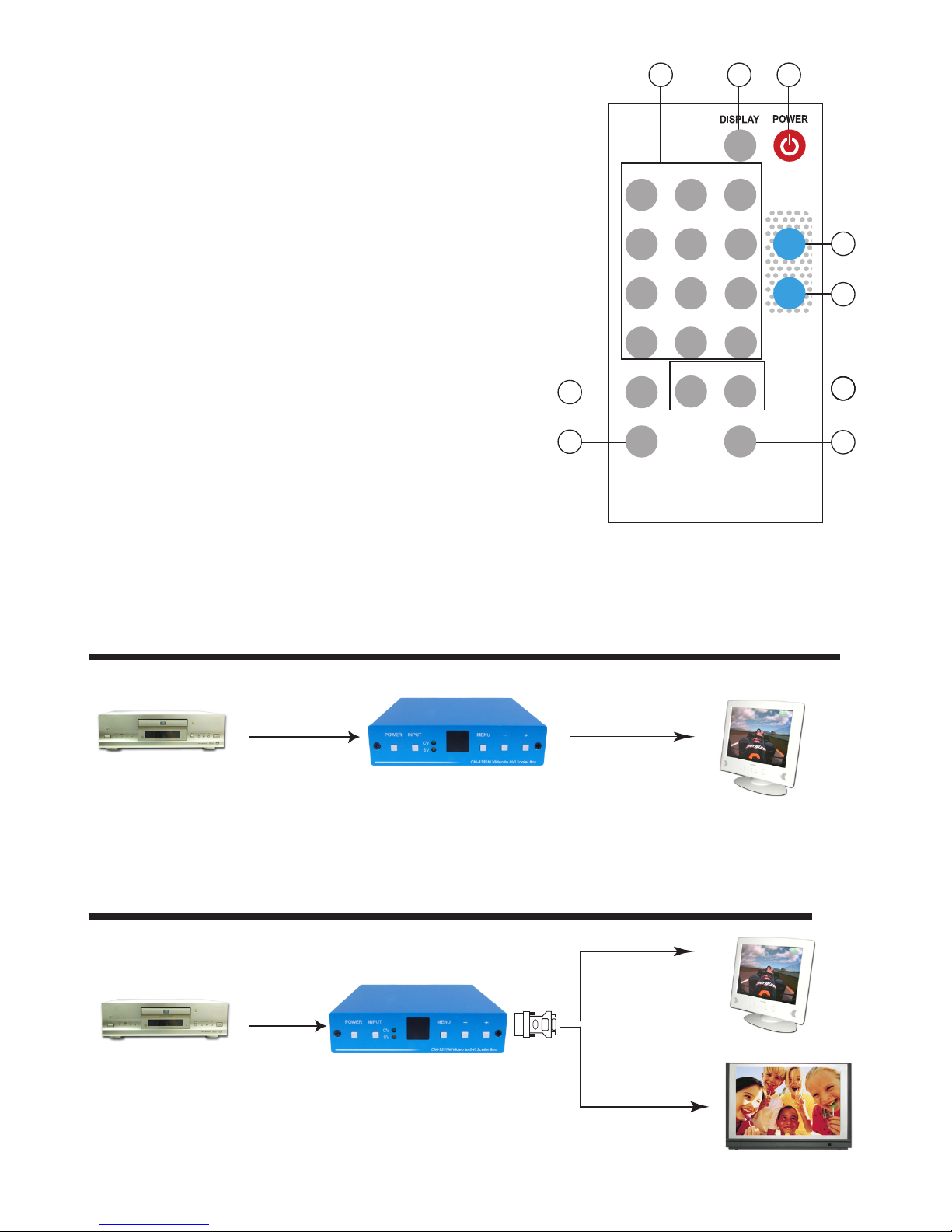
4. Menu/Enter: This button serves two purposes.
a. Press the button to bring up OSD main control menu as shown in the "OSD Operation".
b. To act as a "enter" key to enter sub menu of you selected item or adjust
value of the selected item.
5/6. +/- button: Press the button to move up or down the tick "V" to your
desired parameter. Or after a parameter is selected by pressing MENU/ENTER button,
press the button to alter the value of your selected parameter.
3
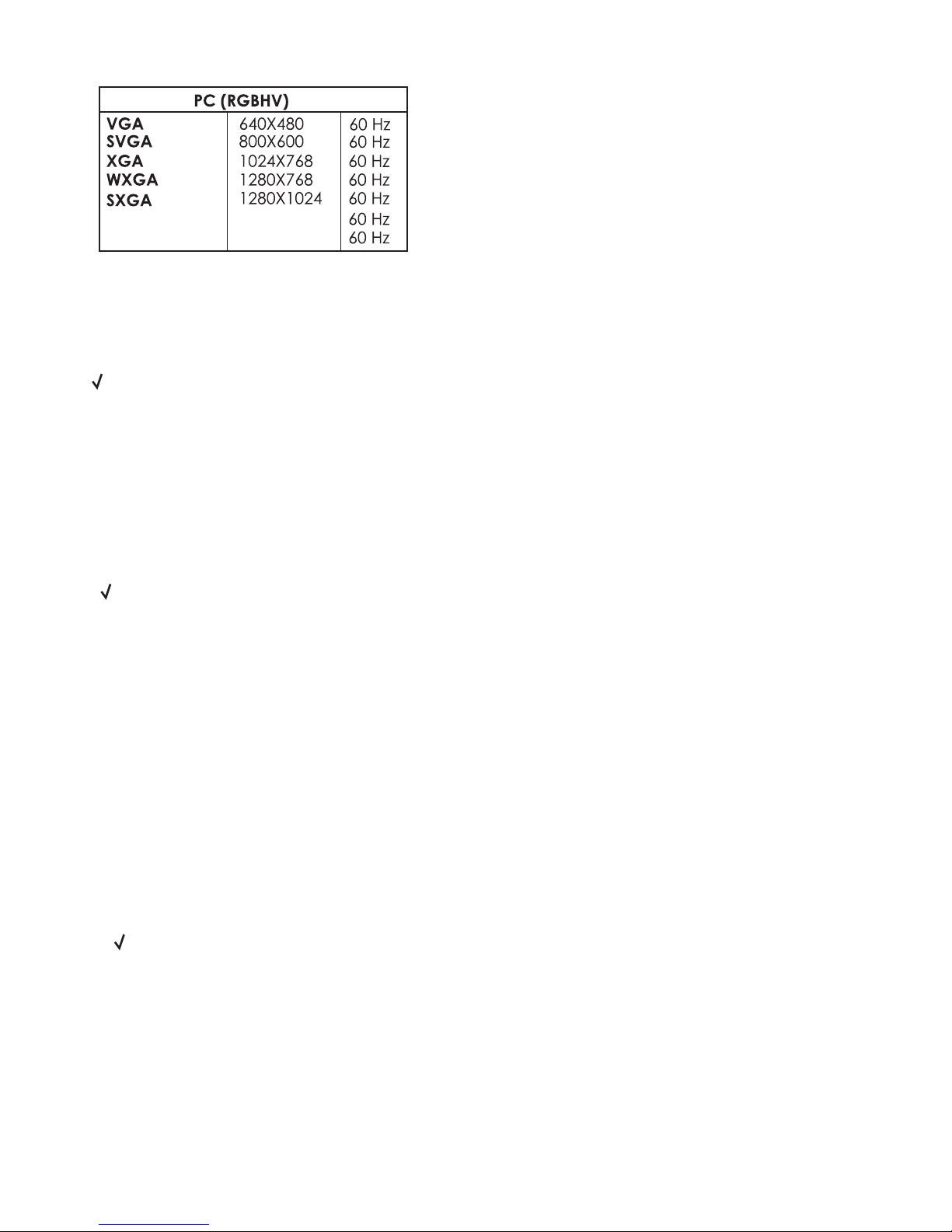
8. Output Format
a. The format of digital DVI output is digital RGB for all resolutions.
-RGB
-RGB
-RGB
-RGB
-RGB
1080i-RGB
720p-RGB
576p-RGB
480p-RGB
1920x1080i
1280X720
720X576
720X480
UXGA
WUXGA -RGB
-RGB 1600 x 1200
1920 x 1200
1080p-RGB
1920x1080p
follow input source
follow input source
follow input source
1. DC power jack: 5V 1A DC power input.
2. Composite Video:
Use a Composite video cable to connect the composite video
output of the source equipment to this composite video(CV) input of the scaler.
3. S-Video: Use a S-Video cable to connect the S-Video output of the source
video equipment to this " S-Video" input on the back of the video scaler.
S-Video provides improved performance over composite video and is
recommended over composite.
4. DVI output: The Video to DVI Scaler Box can output a variety of PC and HDTV
progressive resolutions, in both digital and analog format through DVI-I
connector.
Digital output: Connect Video to DVI Scaler Box's digital DVI output to the DVI
input of your TV/display unit using a DVI to DVI cable.
Analog output: If you are to use Video to DVI Scaler Box's analog output to
connect to the
analog input of your PC or HDTV, you need to use a DVI to VGA
adaptor to pull
out analog signal from the DVI-I connector . The DVI to VGA
adaptor is then connect to the VGA input of your display monitor through a
VGA cable if output is PC resolution,
or connect to the YPbPr input
through
a RCA adaptor cable if output is HD resolution.
Note: DVI to VGA adaptor is not included in the standard package,
and has to order separately.
Rear Panel
4321
DC 5V
SV CV
DVI-I OUTPUT INPUT