Hanwha Techwin Wisenet SPD-150 User manual

NETWORK VIDEO DECODER
User Manual
SPD-150

Copyright
©2017 Hanwha Techwin Co., Ltd. All rights reserved.
Trademark
Each of trademarks herein is registered. The name of this product and other trademarks mentioned in this manual are the registered trademark of
their respective company.
Restriction
Copyright of this document is reserved. Under no circumstances, this document shall be reproduced, distributed or changed, partially or wholly,
without formal authorization.
Disclaimer
Hanwha Techwin makes the best to verify the integrity and correctness of the contents in this document, but no formal guarantee shall be
provided. Use of this document and the subsequent results shall be entirely on the user’s own responsibility. Hanwha Techwin reserves the right
to change the contents of this document without prior notice.
Design and specications are subject to change without prior notice.
The initial administrator ID is “admin” and the password should be set when logging in for the rst time.
Please change your password every three months to safely protect personal information and to prevent the damage of the
information theft.
Please, take note that it’s a user’s responsibility for the security and any other problems caused by mismanaging a password.
Network Video Decoder
User Manual
English _3
● OVERVIEW
IMPORTANT SAFETY INSTRUCTIONS
Read these operating instructions carefully before using the unit.
Follow all the safety instructions listed below.
Keep these operating instructions handy for future reference.
1) Read these instructions.
2) Keep these instructions.
3) Heed all warnings.
4) Follow all instructions.
5) Do not use this apparatus near water.
6) Clean the contaminated area on the product surface with a soft, dry cloth or a damp cloth.
(Do not use a detergent or cosmetic products that contain alcohol, solvents or surfactants or oil
constituents as they may deform or cause damage to the product.)
7) Do not block any ventilation openings, Install in accordance with the manufacturer's instructions.
8) Do not install near any heat sources such as radiators, heat registers, stoves, or other apparatus (including
amplifiers) that produce heat.
9) Do not defeat the safety purpose of the polarized or grounding- type plug. A polarized plug has two blades
with one wider than the other. A grounding type plug has two blades and a third grounding prong. The
wide blade or the third prong are provided for your safety. if the provided plug does not fit into your outlet,
consult an electrician for replacement of the obsolete outlet.
10) Protect the power cord from being walked on or pinched particularly at plugs, convenience receptacles,
and the point where they exit from the apparatus.
11) Only use attachments/accessories specified by the manufacturer.
12) Use only with the cart, stand, tripod, bracket, or table specified by the manufacturer,
or sold with the apparatus. When a cart is used, use caution when moving the cart/
apparatus combination to avoid injury from tip-over.
13) Unplug this apparatus during lightning storms or when unused for long periods of
time.
14) Refer all servicing to qualified service personnel. Servicing is required when the
apparatus has been damaged in any way, such as power-supply cord or plug is
damaged, liquid has been spilled or objects have fallen into the apparatus, the apparatus has been
exposed to rain or moisture, does not operate normally, or has been dropped.
15) This product is intended to be supplied by Listed Power Unit marked "Class 2" or "LPS" and rated 12 Vdc,
Min. 1.8 A.
16) The wired LAN hub providing power over the Ethernet (PoE) in accordance with IEEE 802-3af shall be a
UL Listed device with the output evaluated as a Limited Power Source as defined in UL60950-1.
17) Associated Ethernet wiring shall be limited to inside the building.
overview
Standards Approvals
J `Any changes or modifications in construction of this device which are not expressly approved by the party responsible for
compliance could void the user's authority to operate the equipment.
M
`
This device complies with part 15 of the FCC Rules. Operation is subject to the following two conditions: (1) This device may
not cause harmful interference, and (2) this device must accept any interference received, including interference that may
cause undesired operation.
`
This equipment has been tested and found to comply with the limits for a Class A digital device, pursuant to part 15 of the
FCC Rules. These limits are designed to provide reasonable protection against harmful interference when the equipment is
operated in a commercial environment.
This equipment generates, uses, and can radiate radio frequency energy and, if not installed and used in accordance with the
instruction manual, may cause harmful interference to radio communications. Operation of this equipment in a residential area
is likely to cause harmful interference in which case the user will be required to correct the interference at his own expense.

4_ overview
overview
BEFORE START
This manual provides operational information necessary for using the product and contains a description about each
component part and its function as well as menu or network settings.
You have to keep in mind the following notices :
•Hanwha Techwin retains the copyright on this manual.
•This manual cannot be copied without Hanwha Techwin's prior written approval.
•We are not liable for any or all losses to the product incurred by your use of non-standard product or violation of
instructions mentioned in this manual.
•Prior to opening the case, please consult a qualified technician first. Whenever this is needed power must be
removed from the unit.
Warning
Battery
It is essential that when changing the battery in the unit, the replacement battery must be of the same type
otherwise there may be a possibility of an explosion.
The following are the specifications of the battery you are using now.
•Normal voltage : 3V
•Normal capacity : 210mAh
•Continuous standard load : 0.4mA
•Operating temperature : -20°C ~ +60°C
(-4°F ~ +140°F)
Caution
•Connect the power cord into a grounded outlet.
•The Mains plug is used as a disconnect device and shall stay readily operable at any time.
•Batteries shall not be exposed to excessive heat such as sunshine, fire or the like.
•Risk of Explosion if Battery is replaced by an Incorrect Type. Dispose of Used Batteries According to the
Instructions.
Operating Temperature
The guaranteed operating temperature range of this product is 0°C ~ 40°C (32°F ~ 104°F).
This product may not work properly if you run right after a long period of storage at a temperature below the
guaranteed one.
Prior to using a device that has been stored for a long period in low temperatures, allow the product to stand at
room temperature for a period.
Security Precautions
The initial administrator ID is “admin” and the password should be set when logging in for the first time.
Please change your password every three months to safely protect personal information and to prevent the
damage of the information theft.
Please, take note that it’s a user’s responsibility for the security and any other problems caused by
mismanaging a password.
CALIFORNIA USA ONLY
This Perchlorate warning applies only to primary CR (Manganese Dioxide)
Lithium coin cells in the product sold or distributed ONLY in California USA.
"Perchlorate Material - special handling may apply,
See www.dtsc.ca.gov/hazardouswaste/perchlorate."

English _5
● OVERVIEW
CONTENTS
OVERVIEW
3
3Important Safety Instructions
4Before Start
5Contents
6Features
7Part Names and Functions (Front)
7Part Names and Functions (Rear)
CONNECTING WITH OTHER DEVICE
8
8Connecting to an external device
8Connecting the USB
8Connect Ethernet
8Connect power
9Connecting ground wire
9Connecting the Network
LIVE
10
10 Getting Started
11 Live Screen Configuration
13 Live Screen Mode
14 Audio ON/OFF
15 Set up layout
15 Set up launcher
15 BNC layout settings
MENU SETUP
17
17 System Setup
21 Setting the Device
24 Network Configuration
APPENDIX
26
26 Product Specification
27 Product Overview
27 Default Setting
28 Troubleshooting
29 Open Source License Report on the Product

6_ overview
overview
FEATURES
This product can play back the video and audio captured by network cameras.
•User-friendly UI
•Supports a range of 4K camera resolutions (3840X2160, 4096X2160, 4000X3000)
•Outputs a 4K high definition image using HDMI
•Supports ONVIF Profile S standard and RTP / RTSP protocols
•49 channels simultaneous output (HDMI: 32 channels, VGA: 16 channels, BNC: 1 channel)
•Installation Wizard Function (Easy Setup)
Package Contents
Please unwrap the product, and place the product on a flat place or in the place to be installed.
Please check the following contents are included in addition to the main unit.
VGA VIDEO OUTHDMI NETWORK
ACTLINK
DC12V
Decoder Mouse User Manual CD
User Manual or Quick Manual Terminal block Taping screw
Plastic Anchor
English _7
● OVERVIEW
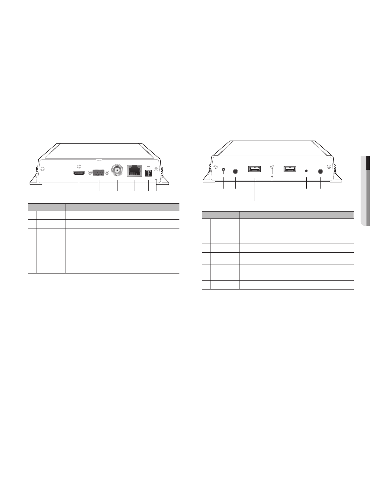
PART NAMES AND FUNCTIONS (FRONT)
Part Names Functions
a
HDMI HDMI connector port.
b
VGA VGA Video Signal Output Port.
c
VIDEO OUT This is a BNC terminal to display video.
d
NETWORK
This is a terminal to connect to Ethernet cable.
`Power input can be provided using PoE. (Please see “Product specifications” for the PoE
power specifications.)
e
DC12V This is a terminal to connect a designated power supply.
f
Ground connection Terminal to connect a separate ground cable.
`Add a ground cable to support the safe use of the device.
PART NAMES AND FUNCTIONS (REAR)
Part Names Functions
a
POWER
It displays the power ON/OFF status using an LED.
- Normal operation: LED ON
- Abnormal operation: LED OFF
b
CONSOLE [CONSOLE] is designed for the service repair purpose only.
c
USB Connects the USB devices.
d
Ground connection Terminal to connect a separate ground cable.
`Add a ground cable to support the safe use of the device.
e
RESET
This button can be used to initialize the device if you have forgotten your password.
If you press and hold the button for about 10 seconds, the password initialization pop-up window
will open, prompting you to reset the password.
f
AUDIO OUT This is a terminal for voice signal output (3.5 π).
VGA VIDEO OUTHDMI NETWORK
ACTLINK
DC12V
a b c d e f
CONSOLE AUDIO OUTPOWER RESETUSB USB
a b d e f
c

8_ connecting with other device
connecting with other device
CONNECT ETHERNET
Connect the Ethernet cable to connect it to a local network or the internet.
It can be connected without a power adapter by supplying power separately from the PoE switch.
`Please see "Product specifications" for the PoE power specifications. (Page 26)
CONNECT POWER
When using a normal Ethernet cable, connect to the power adapter for power supply.
Connect the (+, -) wires of the power adapter to the power input terminal of the network video decoder using a
screwdriver.
J `When using PoE and DC 12V power simultaneously, the device will be operated with the external power (DC 12V).
-
If you use and connect a router with a PoE function, no external power is required.
-
PoE should be compatible with IEEE 802.3af.
`As DC 12V has polarity, be careful when you connect it.
`When connecting external devices, you must first turn off the power to the devices.
`Connect the set and adpater power cable first, and then plug it into a wall socket rated 220V.
`Do not extend the adapter output cable.
`If you need to extend the power cable, contact the service center.
Power Cable Specification for Each Model
Input power Wire Type (AWG) Cable Length (Max.)
DC 12V
#18 19m
#16 30m
CONNECTING TO AN EXTERNAL DEVICE
J `Unrated or improper power source may cause damage to the system. Ensure that you use only the rated power source
before pressing the POWER button.
CONNECTING THE USB
1. On the front of the product, there is a USB port.
2. You can connect USB memory or mouse to the USB port.
3. The product supports hot plugging function that enables connecting/disconnecting USB devices while in
operating the system.
J `Some USB devices may fail to function properly due to compatibility issue, please check the device before using.
`Only USB storage devices that comply with the standards (having a metal cover) are guaranteed for data transfer.
`In case if the USB device’s electric contacts have been worn out, data transfer between the devices may not properly
function.
VGA VIDEO OUTHDMI NETWORK
ACTLINK
DC12V
NETWORK
ACTLINK
1
2
FRONT
USB
VIDEO
DC12V
RESET
12 3 4 5 6 7
VGA OUT VIDEO OUTHDMI OUT
Camera
Microphone
Network
VGA VIDEO OUTHDMI NETWORK
ACTLINK
DC12V
Power
Ethernet
Grounding Cable

English _9
● CONNECTING WITH OTHER DEVICE
CONNECTING GROUND WIRE
Connect the ground wire to the FG screw at the right side of the power input terminal using a screwdriver.
J `Grounding protects the product from being damaged by lightning.
`When connecting, be sure to turn off the power to devices.
Recommended specifications for ground wire
•Length: Maximum 3M
•Thickness: 18AWG or thicker
Ex) UL1007 AWG18/16, UL1015 AWG18/16/14/12, UL2468 AWG18/16/14
CONNECTING THE NETWORK
M
`For more information about network connection, refer to "Network Configuration". (Page 24)
How to install the network video decoder
INTERNET
DDNS Server
(Data Center)
Network Video Decoder
Network Camera

10_ live
live
4. After setting the date/time settings in the <Date/Time>
screen, click on the <Finish> button to launch the setting
completion window.
GETTING STARTED
Starting the system
1. Connect the decoder to the power supply.
2. Initialization will proceed in the order of the icons shown.
3. After step 3, the live screen will appear.
Install Wizard
As shown below, proceed through each step of the <Install Wizard>.
1. In the <Language> screen, select the language and press
the <Next> button.
2. In the <ID/PW> screen, set the password and press
<Next>.
3. In the <Network> screen, set the network access method
and the access environment. To use a simple intranet, click
<Next>.
•Network (Camera) : Connects to the camera and receives the
video feed from the camera
•Network Setup
- IP Type : Choose the network connection method.
- IP Address, Subnet Mask, Gateway, DNS
M
`If the LAN cable is not connected to the port, the setting button will not be activated for use. Check the LAN cable
connection.
`For more details on network settings, refer to the user manual.
English _11
● LIVE
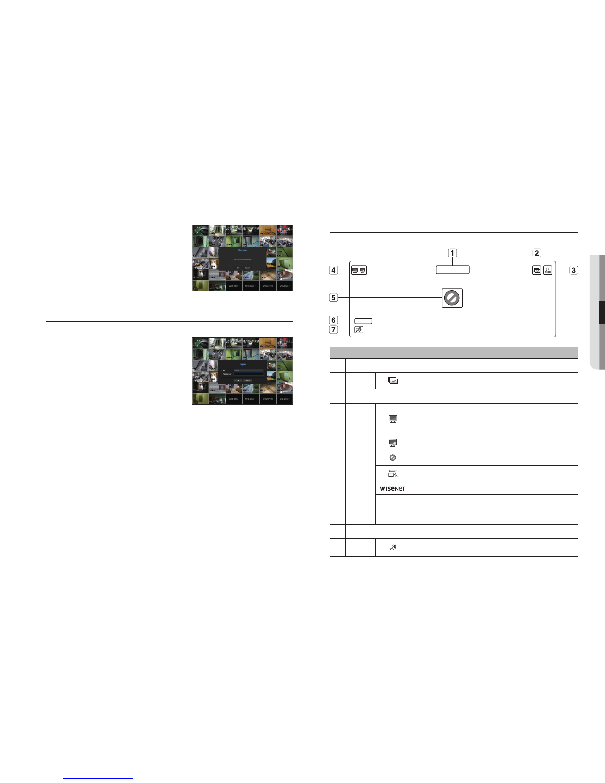
Shutting Down the System
1. In the live screen menu, select <Shutdown>.
2. The “Shutdown” confirmation pop-up window will appear.
3. Click on <OK>.
The system will shut down.
M
`Only the user with the "shutdown" permission can shut down
the system.
`For the permission management, refer to "User > Setting
Permissions". (Page 18)
Login
To use the Decoder menu, you are required to login as a user that is authorized to access the applicable menu.
1. Right click with your mouse button on the live mode screen.
You will see the context menu on the screen as shown.
2. Select <Login>.
The login dialog appears.
J `The initial administrator ID is set to "admin" and you will need to
configure the password in the installation wizard.
`Please change your password every three months to safely protect
personal information and to prevent the damage of the information
theft.
Please, take note that it’s a user’s responsibility for the security and any other problems caused by mismanaging a password.
M
`For the restricted permission, refer to "User > Setting Permissions". (Page 18)
LIVE SCREEN CONFIGURATION
Icons on the Live Screen
You can check the status or operation of the Decoder with the icons on the live screen.
Name Description
a
Current Date, Time
Displays the current time and date.
b
Screen Mode
FULL NO RAIDRAID
SCSI
It is displayed when all the channels are switched at the set time interval.
c
Login Information
When you are logged in, the "LOG ON" icon will be displayed.
d
System
Operation
FULL NO RAIDRAID
SCSI
It is displayed when the network is overloaded.
`It occurs when the max receiving allowance is exceeded, causing an overload to the
CPU. It will disappear if you modify the camera settings or delete a camera to reduce
the performance burden.
FULL NO RAIDRAID
SCSI
It is displayed when there is firmware to update the server.
e
Video Input
Status
Displayed if no input is entered in the condition that the camera is set to <ON>.
FULL NO RAIDRAID
SCSI
Displayed when the live image with the camera turned <ON> exceeds the supported
resolution.
It displays unsupported channels. (Display 32 channels of video in 36 splits)
If a camera is <OFF>, or if no camera is registered, or it is in <Covert2> mode, nothing
will be displayed on the screen.
If the camera is set to <Covert1>, the video will be displayed but the OSD menus will not
be displayed.
f
Camera Title / Channel Display the camera title and channel number.
g
Camera
Operation
FULL NO RAIDRAID
SCSI
Displays AUDIO ON/MUTE. Not displayed in video mode if deactivated.
CAM 01
2016-01-01 00:00:01
FULL NO
FULL NO
FULL NO RAIDRAID
SCSI
FULL NO RAIDRAID
SCSI
12_ live
live
Live Screen Menu
If you right click with your mouse button in live screen mode, it will launch the live screen menu where you can
access each menu.
The context menu differs depending on the state of Log in/out, split mode, and Decoder operation status.
Single Mode Menu
The single mode menu is available only in Single Mode.
Menu Description
a
Full Screen Select and click a desired channel in Split mode to switch to the full screen of the selected
channel.
Split Mode Menu
In Live split mode, right-click to display this context menu as shown.
The context sensitive menu in split mode differs, depending on the login/logout status.
Menu Description
a
Status This shows the connection information and live status of the cameras connected to each
channel. Please see “Status”. (Page 13)
b
Audio On/Off Turns ON/MUTE the sound of the selected channel.
Refer to “Audio ON/OFF”. (Page 14)
c
Channel Setup Select single channel or multi-channel to change the settings of each channel.
Refer to “Channel Setup”. (Page 14)
d
Menu Enter the main menu. Refer to the menu settings. (Page 17)
e
Shutdown
The system shutdown dialog will appear.
f
Login/Logout You can log in or out.
g
Show/Hide Launcher
Shows or hides the launcher.
Status ►
Audio ►
Channel Setup ►
Menu
Shutdown
Logout
Hide Launcher
< Single Mode Menu >
Full Screen
Status ►
Audio ►
Channel Setup ►
Menu
Shutdown
Logout
Hide Launcher
< One channel selection menu in the split screen >
a
Status
►
Audio off
Channel Setup
►
Menu
Shutdown
Logout
Hide Launcher
gfedcba

English _13
● LIVE
LIVE SCREEN MODE
You can play up to 64 live video channels in single, 10-split, or auto sequence mode.
Method for displaying screen mode
If you want to change to split mode, select 'split mode' in the layout settings.
CH1 CH2 CH3 CH4 CH5 CH6
CH7 CH8 CH9 CH10 CH11 CH12
CH13 CH14 CH15 CH16 CH17 CH18
CH19 CH20 CH21 CH22 CH23 CH24
CH25 CH26 CH27 CH28 CH29 CH30
CH31 CH32
CH1 CH2 CH3 CH4 CH5
CH6 CH7 CH8 CH9 CH10
CH11 CH12 CH13 CH14 CH15
CH16 CH17 CH18 CH19 CH20
CH21 CH22 CH23 CH24 CH25
CH1 CH2 CH3 CH4
CH5 CH6 CH7 CH8
CH9 CH10 CH11 CH12
CH13 CH14 CH15 CH16
CH1 CH2 CH3
CH4 CH5 CH6
CH7 CH8 CH9
36-split mode 25-split mode 16-split mode 9-split mode
CH1 CH2
CH3 CH4 CH1 CH2 CH3 CH1 CH2
CH2
CH1 CH3
CH4 CH5 CH6
4-split mode 3-split mode 2-split mode 6-split mode
CH2
CH3
CH1 CH4
CH5 CH6 CH7 CH8
CH2 CH3 CH4 CH5
CH6 CH7
CH8 CH1 CH9
CH10 CH11 CH12 CH13 CH1 CH1
8-split mode 13-split mode Single mode Auto Sequence
Status
You can check the connection information of the camera to be connected to each channel on the live screen.
Channel info
If you select <CH Info> in the <Status> menu on the live
screen, the information of an incoming video on the live
screen that you are currently monitoring is output.
M
`The letter marked next to the model name indicates the
protocol used when registering the camera.
-S and V indicates Samsung protocol, O indiates ONVIF and
R indicates RTSP.
J `If connected via RTSP or IPv6, it will not show the IP address.
RES : 1920X1080(H.264)
SET/IN/DEC : 30/30.0/30.0
SNB-6004 (S)
IP : XXX.XXX.XX.XX
RES : 1920X1080(H.264)
SET/IN/DEC : 30/30.0/30.0
SNB-6004 (S)
IP : XXX.XXX.XX.XX
Connection
If you select <Connection> in the <Status> menu on the live
screen, you can check the connection state of the camera
connected to each channel.
M
`Please refer to "Register camera > Error code guide" for details
regarding camera connection errors. (Page 21)
Live Status
If you select <Live> in the <Status> menu on the live screen, you can check the transmisson information and
state of the camera connected to each channel.
•Model : Displays the camera model name connected to each channel.
•Status : Displays the status of camera connection set to each channel.
•IP Address : Displays the IP address of a camera set to each channel.
•Codec : Displays the live profile codec information for a camera set to each channel.
•Resolution : Displays the live profile resolution of a camera set to each channel.
•Frame Rate : Displays the live profile transmission rate for a camera set to each channel.

14_ live
live
AUDIO ON/OFF
You can turn the sound on/off corresponding to the channel in Live mode.
AUDIO ON/OFF in Single mode
Click on the audio icon ( ) on the screen to turn it ON/OFF.
M
`If there is no sound even though the output settings have been properly configured, confirm that the connected network
camera supports the audio function, and check to ensure that the audio settings are properly configured.
The sound icon can be displayed if the sound signal fails to output from noise.
`Only the channel where <AUDIO> is set to <ON> in "Setting the Device > Camera" displays the audio icon ( ) in Live
mode that you can use to turn the sound on/off.
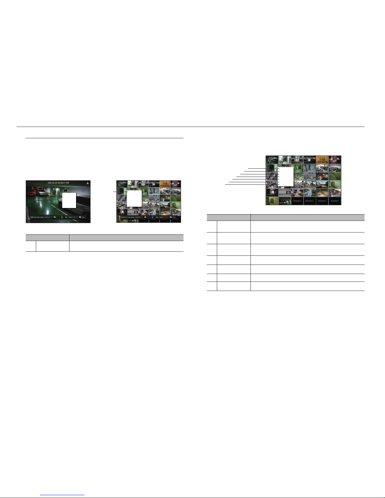
Channel Setting
While checking the video of registered channels, change the name of the channel to a name that makes sense
for the video being captured.
1. Place the cursor over the camera name of each channel to display the <
▼
> key to the right on the screen.
2. Click a camera name to display a channel list where you can select a different channel.
3. Select a desired channel and click it.
The current channel will be switched to the selected one.
Use the cursor to select a channel to move, and drag and drop it to a desired channel; this can also change
the channel position.
`Ex : if switching CH 1 to CH 7
Switching to Single Mode
When in split mode, select and double-click a desired channel to switch to its Single mode.
`Ex : If double-clicking CH 3.
CH1
CH1
CH1
CH1
CH2
CH1
CH2
CH6
CH8
CH10 CH11 CH12 CH13
CH3 CH4 CH5
CH7
CH9
CH1
CH5 CH6 CH7 CH8
CH2
CH3
CH4
CH2
CH3
CH2
CH3 CH4
CH2 CH3
CH4 CH5 CH6
CH4 CH5 CH6
CH7 CH8 CH9
CH1 CH2 CH3 CH4
CH5 CH6 CH7 CH8
CH9 CH10 CH11 CH12
CH13 CH14 CH15 CH16
CH1
CH1
CH1
CH1 CH2
CH3 CH4
CH2 CH3
CH4 CH5 CH6
CH7 CH8 CH9
CH5 CH6
CH7 CH8
CH9 CH10
CH11 CH12
CH13 CH14
CH15 CH16
CH10 CH11 CH12
CH13 CH14 CH15
CH16
CH7 CH2 CH3 CH4
CH5 CH6 CH1 CH8
CH9 CH10 CH11 CH12
CH13 CH14 CH15 CH16 CH3 CH1
CH1 CH2
CH1 CH2
CH3 CH4
CH1
CH1CH7 CH8
CH4
CH3
CH2
CH5
CH1
CH6 CH12
CH1
CH13
CH19
CH4
CH7
CH5
CH10
CH8
CH11
CH6
CH2 CH3
CH4 CH5
CH2
CH6
CH1 CH3
CH7 CH8 CH9
CH1 CH2
CH3 CH4
CH5 CH6
CH7 CH8
CH9 CH10
CH11 CH12
CH13 CH14
CH15 CH16
CH1
CH4 CH5
CH2
CH6
CH1 CH3
CH7 CH8 CH9
CH13 CH14
CH11
CH15
CH10 CH12
CH16
CH1 CH3
CH2
CH4 CH5 CH6
CH1
CH2
CH1 CH2
CH3 CH1
CH15
CH11
CH16
CH12
CH7
CH3
CH8
CH4
CH13
CH9
CH14
CH10
CH5
CH1
CH6
CH2
CH15
CH11
CH16
CH12
CH7
CH3
CH8
CH4
CH13
CH9
CH14
CH10
CH5
CH1
CH6
CH2
CH15
CH11
CH16
CH12
CH1
CH3
CH8
CH4
CH13
CH9
CH14
CH10
CH5
CH7
CH6
CH2
CH1
CH1
CH1
CH1
CH2
CH1
CH2
CH6
CH8
CH10 CH11 CH12 CH13
CH3 CH4 CH5
CH7
CH9
CH1
CH5 CH6 CH7 CH8
CH2
CH3
CH4
CH2
CH3
CH2
CH3 CH4
CH2 CH3
CH4 CH5 CH6
CH4 CH5 CH6
CH7 CH8 CH9
CH1 CH2 CH3 CH4
CH5 CH6 CH7 CH8
CH9 CH10 CH11 CH12
CH13 CH14 CH15 CH16
CH1
CH1
CH1
CH1 CH2
CH3 CH4
CH2 CH3
CH4 CH5 CH6
CH7 CH8 CH9
CH5 CH6
CH7 CH8
CH9 CH10
CH11 CH12
CH13 CH14
CH15 CH16
CH10 CH11 CH12
CH13 CH14 CH15
CH16
CH7 CH2 CH3 CH4
CH5 CH6 CH1 CH8
CH9 CH10 CH11 CH12
CH13 CH14 CH15 CH16 CH3 CH1
CH1 CH2
CH1 CH2
CH3 CH4
CH1
CH1CH7 CH8
CH4
CH3
CH2
CH5
CH1
CH6 CH12
CH1
CH13
CH19
CH4
CH7
CH5
CH10
CH8
CH11
CH6
CH2 CH3
CH4 CH5
CH2
CH6
CH1 CH3
CH7 CH8 CH9
CH1 CH2
CH3 CH4
CH5 CH6
CH7 CH8
CH9 CH10
CH11 CH12
CH13 CH14
CH15 CH16
CH1
CH4 CH5
CH2
CH6
CH1 CH3
CH7 CH8 CH9
CH13 CH14
CH11
CH15
CH10 CH12
CH16
CH1 CH3
CH2
CH4 CH5 CH6
CH1
CH2
CH1 CH2
CH3 CH1CH15
CH11
CH16
CH12
CH7
CH3
CH8
CH4
CH13
CH9
CH14
CH10
CH5
CH1
CH6
CH2
CH15
CH11
CH16
CH12
CH7
CH3
CH8
CH4
CH13
CH9
CH14
CH10
CH5
CH1
CH6
CH2
CH15
CH11
CH16
CH12
CH1
CH3
CH8
CH4
CH13
CH9
CH14
CH10
CH5
CH7
CH6
CH2
;
CH1
CH1
CH1
CH1
CH2
CH1
CH2
CH6
CH8
CH10 CH11 CH12 CH13
CH3 CH4 CH5
CH7
CH9
CH1
CH5 CH6 CH7 CH8
CH2
CH3
CH4
CH2
CH3
CH2
CH3 CH4
CH2 CH3
CH4 CH5 CH6
CH4 CH5 CH6
CH7 CH8 CH9
CH1 CH2 CH3 CH4
CH5 CH6 CH7 CH8
CH9 CH10 CH11 CH12
CH13 CH14 CH15 CH16
CH1
CH1
CH1
CH1 CH2
CH3 CH4
CH2 CH3
CH4 CH5 CH6
CH7 CH8 CH9
CH5 CH6
CH7 CH8
CH9 CH10
CH11 CH12
CH13 CH14
CH15 CH16
CH10 CH11 CH12
CH13 CH14 CH15
CH16
CH7 CH2 CH3 CH4
CH5 CH6 CH1 CH8
CH9 CH10 CH11 CH12
CH13 CH14 CH15 CH16 CH3 CH1
CH1 CH2
CH1 CH2
CH3 CH4
CH1
CH1CH7 CH8
CH4
CH3
CH2
CH5
CH1
CH6 CH12
CH1
CH13
CH19
CH4
CH7
CH5
CH10
CH8
CH11
CH6
CH2 CH3
CH4 CH5
CH2
CH6
CH1 CH3
CH7 CH8 CH9
CH1 CH2
CH3 CH4
CH5 CH6
CH7 CH8
CH9 CH10
CH11 CH12
CH13 CH14
CH15 CH16
CH1
CH4 CH5
CH2
CH6
CH1 CH3
CH7 CH8 CH9
CH13 CH14
CH11
CH15
CH10 CH12
CH16
CH1 CH3
CH2
CH4 CH5 CH6
CH1
CH2
CH1 CH2
CH3 CH1
CH15
CH11
CH16
CH12
CH7
CH3
CH8
CH4
CH13
CH9
CH14
CH10
CH5
CH1
CH6
CH2
CH15
CH11
CH16
CH12
CH7
CH3
CH8
CH4
CH13
CH9
CH14
CH10
CH5
CH1
CH6
CH2
CH15
CH11
CH16
CH12
CH1
CH3
CH8
CH4
CH13
CH9
CH14
CH10
CH5
CH7
CH6
CH2
CH1
CH1
CH1
CH1
CH2
CH1
CH2
CH6
CH8
CH10 CH11 CH12 CH13
CH3 CH4 CH5
CH7
CH9
CH1
CH5 CH6 CH7 CH8
CH2
CH3
CH4
CH2
CH3
CH2
CH3 CH4
CH2 CH3
CH4 CH5 CH6
CH4 CH5 CH6
CH7 CH8 CH9
CH1 CH2 CH3 CH4
CH5 CH6 CH7 CH8
CH9 CH10 CH11 CH12
CH13 CH14 CH15 CH16
CH1
CH1
CH1
CH1 CH2
CH3 CH4
CH2 CH3
CH4 CH5 CH6
CH7 CH8 CH9
CH5 CH6
CH7 CH8
CH9 CH10
CH11 CH12
CH13 CH14
CH15 CH16
CH10 CH11 CH12
CH13 CH14 CH15
CH16
CH7 CH2 CH3 CH4
CH5 CH6 CH1 CH8
CH9 CH10 CH11 CH12
CH13 CH14 CH15 CH16 CH3 CH1
CH1 CH2
CH1 CH2
CH3 CH4
CH1
CH1CH7 CH8
CH4
CH3
CH2
CH5
CH1
CH6 CH12
CH1
CH13
CH19
CH4
CH7
CH5
CH10
CH8
CH11
CH6
CH2 CH3
CH4 CH5
CH2
CH6
CH1 CH3
CH7 CH8 CH9
CH1 CH2
CH3 CH4
CH5 CH6
CH7 CH8
CH9 CH10
CH11 CH12
CH13 CH14
CH15 CH16
CH1
CH4 CH5
CH2
CH6
CH1 CH3
CH7 CH8 CH9
CH13 CH14
CH11
CH15
CH10 CH12
CH16
CH1 CH3
CH2
CH4 CH5 CH6
CH1
CH2
CH1 CH2
CH3
CH1CH15
CH11
CH16
CH12
CH7
CH3
CH8
CH4
CH13
CH9
CH14
CH10
CH5
CH1
CH6
CH2
CH15
CH11
CH16
CH12
CH7
CH3
CH8
CH4
CH13
CH9
CH14
CH10
CH5
CH1
CH6
CH2
CH15
CH11
CH16
CH12
CH1
CH3
CH8
CH4
CH13
CH9
CH14
CH10
CH5
CH7
CH6
CH2
;
aRename single channel
Select one channel from the <Channel Setup> menu of the live screen, and click <Single Channel Change>
to change the name of the channel.
`Please refer to “Use virtual keyboard”. (Page 17)
bSet up multi-channels
You can set up anything related to video by channel.
•Select the channel you want to change in live and move to <multi-channel settings>, and then the focus
will shift to the video.
You can change related information immediately by referring to the selected video.
M
`Please see "Channel Setting" for details about the settings. (Page 23)
Single Channel Change
Multi Channel Setup
Full Screen
Status ►
Audio ►
Channel Setup ►
Menu
Shutdown
Logout
Show Launcher
Single Channel Change
Multi Channel Setup
Full Screen
Status ►
Audio ►
Channel Setup ►
Menu
Shutdown
Logout
Show Launcher
a
b

English _15
● LIVE
SET UP LAYOUT
You can set up the layout of each channel from the live screen.
aDesignate the channel name related to the video through the single channel or multi-channel settings in the live
screen.
Please see "Channel Setting".
bRun the layout settings screen at launch.
cSet up layout by composing the split screen mode with channel names.
You can set up multiple desired layouts at the same time.
dAfter settings, you can check it out while changing layout, and change the order of channels by clicking with the
mouse in the relevant order.
eIt will replay the live screen using different layouts in consecutive order for the sequence setting time.
`Check <Use layout sequence> in the layout settings window to set up the sequence conversion time.
SET UP LAUNCHER
You can set up the video output layout by using the launcher menu at the bottom of the live screen.
1. Select <Show launcher> from the live screen menu.
2. Click the launcher menu on the bottom of the screen to enter the menu directly.
M
`If there is no input within 10 seconds, it will disappear.
`The launcher menu can only be selected by clicking.
• : Select the layout to be displayed on the screen from among the layouts you set up.
This is a layout list batch added from the HDMI/VGA layout settings page, and will be changed when you
change it.
• :
It shows the list of cameras registered at BNC layout, and only those cameras can be selected.
• : Set up, change or delete the layout of each channel.
• : Run the sequence.
HDMI/VGA layout settings
Bundle channels based on user needs, to check them immediately when necessary.
1. Select < >.
The layout settings window will appear.
•New : You can set up a new layout.
•Rename : Select the layout you want to set up and change the name.
•Import : Select and import layouts from the layout list (HDMI, VGA) you have set up already.
•Delete : You can delete a layout you set up previously.
•Use layout sequence : Select whether or not you want to use the layout sequence.
•Sequence switching time : The time when the layout split screen is automatically converted is set up.
•Split Mode : Select split mode from the layout mode.
`VGA layout supports up to 16 splits. However, the layout with 25 and 36 splits will be excluded from the HDMI layout list while
importing the layout list.
`<> is a single channel sequence, and will be excluded from the layout sequence operation of the live launcher.
`: Live launcher sequence is a layout sequence, and it will be included in the sequence usage and
selection in the layout settings page.
•Select channel: Select the channels which compose the layout.
`Drag the channel selected from the layout at the right of the screen to move the channel.
2. Push <Save> to save the layout.
M
`VGA layout and settings can be accessed through "Devices > Monitor > Expand".
BNC LAYOUT SETTINGS
BNC sequence will be operated through the selected channels.
M
`BNC channel settings and sequence can be used when "Devices > Monitor > BNC Output" in the settings is selected as
<ON>.
c
d b e
Single Channel Change
Multi Channel Setup
Full Screen
Status ►
Audio ►
Channel Setup ►
Menu
Shutdown
Logout
Hide Launcher
a

16_ live
live
Configure live monitoring
M
`Please see each page for details of settings.
1. Camera registration (Page 21) > 2. Designate Live channel name (Page 14) > 3. Layout settings (Page 15) >
4. Layout monitoring (Page 15)
1. Camera registration
Full Screen
Status ►
Audio ►
Channel Setup ►
Menu
Shutdown
Logout
Show Launcher
2. Designate Live channel name
Single Channel Change
Multi Channel Setup
Full Screen
Status ►
Audio ►
Channel Setup ►
Menu
Shutdown
Logout
Show Launcher
3. Layout settings
4. Layout monitoring
HDMI OUT VGA OUT BNC OUT
English _17
System environment, device and network can be set up.
SYSTEM SETUP
You can setup Date/Time/Language, User, System Properties and Log.
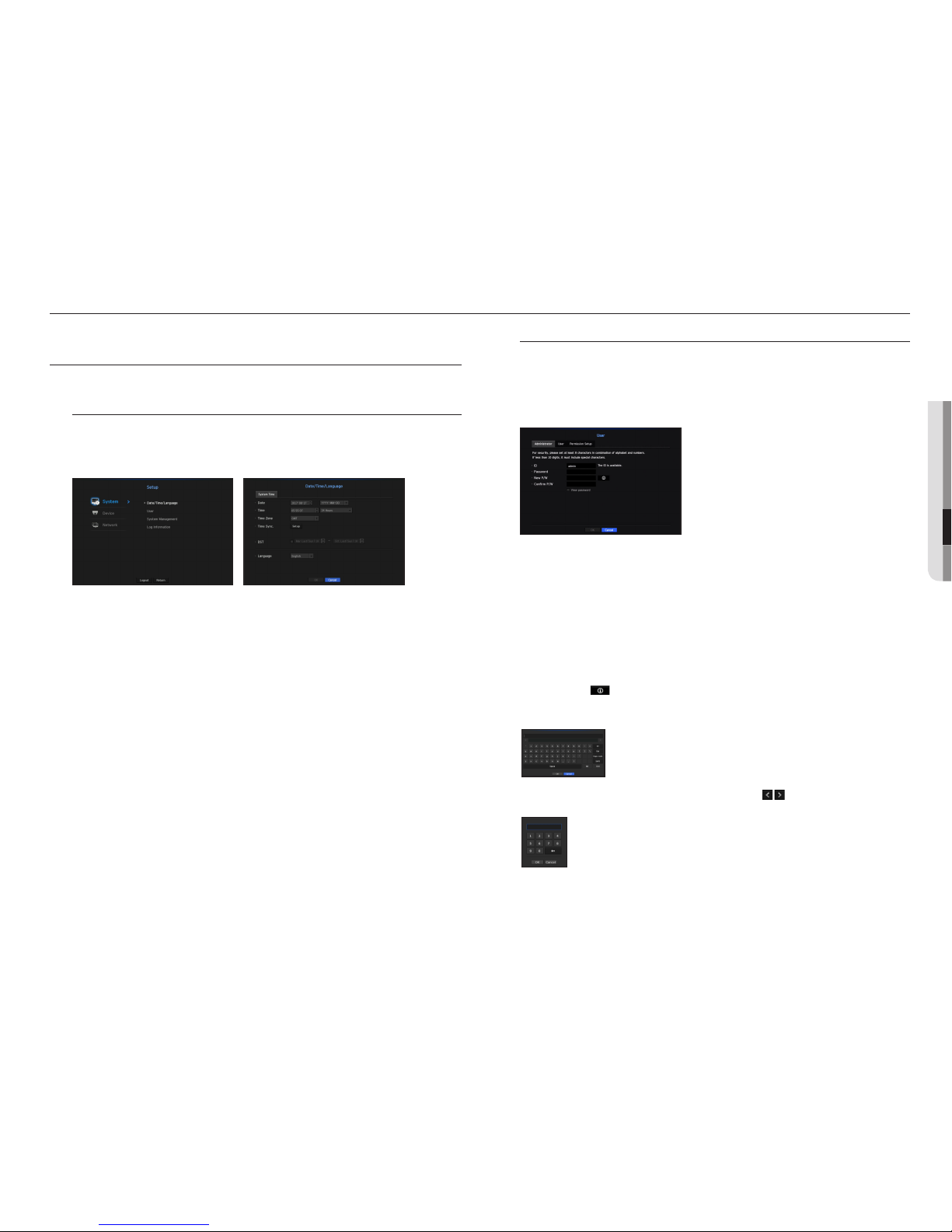
Date/Time/Language
Setting the Date/Time/Language
You can check and setup the current Date/Time and time related properties, as well as the language used for
the interface on the screen.
•Date : Sets the date and its format that will appear on the screen.
•Time : Sets the time and its format that will appear on the screen.
•Time Zone : Sets the time zone of your area based on the Greenwich Mean Time (GMT).
`GMT (Greenwich Mean Time) is standard World Time and the basis of world time zone.
•Time Sync. : Specify the use of synchronization with the time server.
Click the <Setup> button to display time synchronization setup screen.
If you select to use the <Time Server>, the current time will be synchronized on a regular basis by the server
defined as <Time Server>.
If this is the case, you cannot change the time setting manually.
- Synchronization : Specify the use of synchronization with the time server.
- Time Server : Enter an IP or URL address of the time server.
- Last Sync Time : Displays the most recent synchronization time from the selected time server.
•DST : Set up Daylight Saving Time with its period to make the time earlier than the GMT of its time zone by 1
hour during the set period.
•Language : Select your language. Sets the language for the interface.
English, French, German, Spanish, Italian, Chinese, Russian, Korean, Polish, Japanese, Dutch, Portuguese,
Turkish and Swedish languages are supported.
User
You can set permissions of each user over the Decoder's specific function and settings.
Setting the Administrator
You can set and change Administrator's ID and password.
The administrator can use and set all menu items and functions.
•ID : Change the admin ID.
•Password : Checks the current password.
•New P/W : Enter new password.
•Confirm P/W : Confirms the new password.
`If <View password> is selected, the password will no longer be hidden on the screen when you type it.
M
`The initial administrator ID is set to "admin" and you will need to configure the password in the installation wizard.
`Please change your password every three months to safely protect personal information and to prevent the damage of the
information theft.
Please, take note that it's a user's responsibility for the security and any other problems caused by mismanaging a password.
`If you click < >, a basic guide for password setup is displayed.
Using Virtual Keyboard
1. For alphanumeric inputs, the virtual keyboard window appears.
2. Using a mouse, click on the desired character tab.
3. In the upper text input box of the virtual keyboard, there displays a list of
candidate words containing the selected character.
4. Select a word from the list, or use the keyboard to enter the whole word.
`If there are many of candidate words, use < > buttons to move between them forward
and backward.
5. Select <OK>.
Entered word is applied.
`For upper case letters, use <Caps Lock> button.
`For special characters, use <Shift> button.
`Using the virtual keyboard is the same to a normal keyboard use in your region.
`ID allows alphanumeric characters only.
`The password should at a minimum be an 8-digit combination of alphabetical letters and
numbers.
● MENU SETUP
menu setup

User setting
You can create a group or set permissions for each group.
You can add a user and edit the registered user information.
If you want to add a group
1. Click on the [ ] button to launch the Group Addition popup window.
If you want to add a group, click on <OK>.
2. Press the group name item to launch the virtual keyboard used to enter group names.
Enter the group name to register.
`You can add a maximum of 10 groups.
If you want to set group permission
Set permission to access each group.
Each group's users can only access items with a check mark beside them.
1. Select the menu to set group permissions.
The menu with access permissions will appear when a user of the group logs in.
•Menu : You can select and set the setting menu that can be accessed. A group user can only access the
menu selected. If you select the menu, the menu permission setting screen will be displayed.
•Shutdown : Authority for exiting the system will be given.
2. Click <OK>.
Check a group user to give them the permission to access the selected item.
If you want to register a user
1. Click on the [ ] button to launch the user addition popup window.
To add a user, click on <OK>.
2. Select a group.
When registering a user, the selected group will be automatically registered.
`A group can be changed after inputting all required information.
3. Enter name, ID and password.
4. Click <OK>.
Registered user information will be saved.
When you want to delete the group and user information
1. To delete, click on the [ ] button.
2. The deletion confirmation window will appear and you can select an item to delete and click on <Delete>.
Setting Permissions
You can set up an automatic log-out time and whether you are required to enter an ID manually or not.
•Auto Log out : A user will be automatically logged out if there is no operation on Decoder for over set period
of time.
•Manual Input of ID : In the login window, select whether to enter ID.
18_ menu setup
menu setup
English _19
If the user has restricted access
If a new group is restricted to access the entire menus, the users belonging to the group can access only the
basic menus and can change only their respective password.
If all permissions are restricted, you will see only some menu items accessible in the Live screen menu.
To change the user password
If you log in with the user account of a group with restricted access, you just can change your own password.
1. Provide the login information.
2. Select <User Menu>.
The Permission Management screen appears.
3. Select <User>.
The Password dialog shall appear.
4. Provide a new password.
5. Select <OK>.
The old password will be changed to a new one.
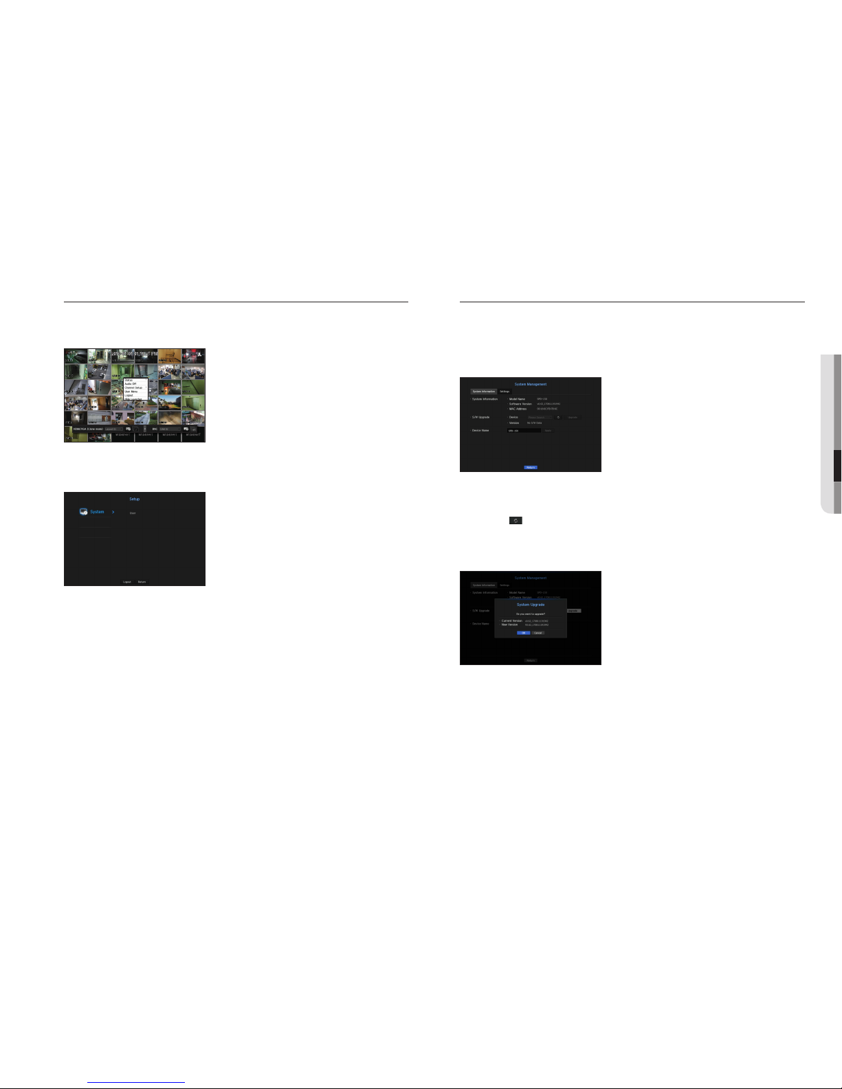
System Management
You can check the current system version and upgrade to the newest version, or run settings, backup or
initialization of settings.
Checking the System Information
You can check the current software version and MAC address before proceeding with the upgrade.
•System Information : Shows the current system's information.
The values can not be changed by a user.
•S/W Upgrade : Updates the Decoder's software up to date.
- Press the < > button to search for and display the equipment to upgrade.
•Device Name : This is the name of the decoder.
To upgrade the current software version
1. Connect a device storing the software to be updated.
`It may take about 10 seconds to recognize the device.
`Upgradeable devices include USB memory, and network device.
`When the network is upgraded, the current decoder must be connected to the network.
Upgrade via the proxy server may not be enabled due to the restricted access.
2. Select <System Management> from <System> window.
3. Select <System Information>.
● MENU SETUP
4. When the recognized device appears, select <Upgrade>.
`If you connect a device in the upgrade menu window, you can press the < > button to search for available software.
`If there is an upgrade image on the network, the popup window will appear.
`The <Upgrade> button will be activated only if the current <Software Version> of the <System Information> is same to or
older than that of <S/W Upgrade>.
5. Press <OK> in the "S/W Upgrade" window.
`While updating, it shows the progress.
6. When the updating is done, it automatically restarts.
Do not turn the power off until it finishes restarting.
M
`If "Upgrade Failed" appears, retry from the step 4.
When you experience continued failure, consult the service center for assistance.
Settings
You can copy and import the Decoder settings by using a storage media.
•Storage Device : Shows the connected storage device.
- Press the < > button to view the list of storage devices.
- Format : Connected USB device will be formatted.
•Export : Exports Decoder settings to the connected storage device.
•Import : Imports Decoder settings from the storage device and applies to the Decoder.
- Uncheck the checkbox of an item(s) that you want to import.
Only the other items than the selected one will be applied to the Decoder.
`<Export> and <Import> settings should be used in the same software version.
•Load Factory Default : Restore the factory default settings of Decoder.
Uncheck the checkbox of an item(s) that you want to reset. Then, only the other items than the selected one
will return to the factory default.
If <Initialization> is selected, a confirmation dialog for "Load Factory Default" prompts. Press <OK> to
initialize the system to the factory default.
M
`If you want to initialize the <Authority Setting>, you need to reset the password.
In case you reboot, reset it the Installation Wizard and if not, use the guide screen to reset it.
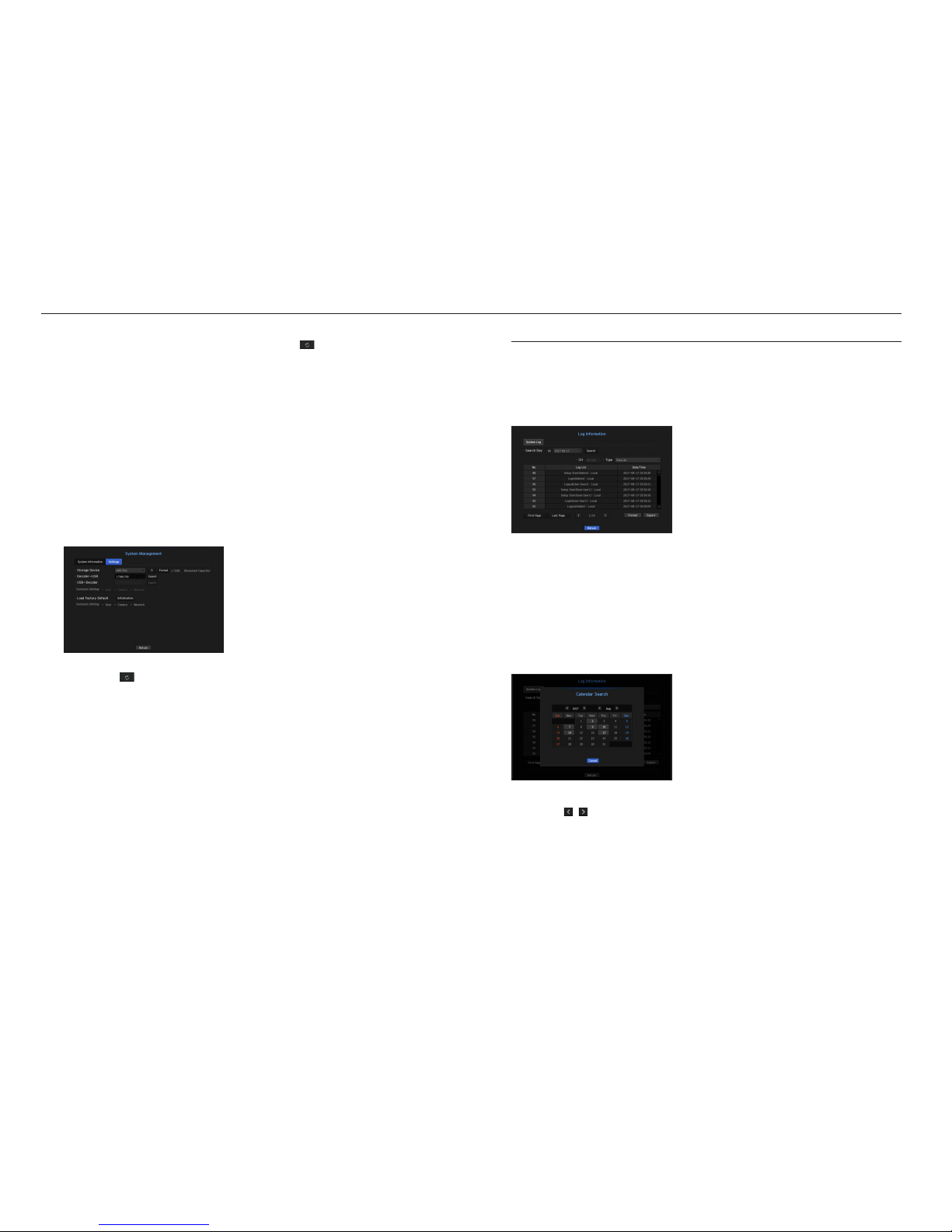
Log Information
You can check out the record information related to the system.
Checking the system log
System Log shows log and timestamp on every system start up, system shutdown, and changes on system
settings.
•Search Day : Click the Calendar icon to display the calendar window, or use the direction buttons to specify
the search period of the system log.
•Search : Specify the date and press this button to display the search result in the log list.
•Type : When there are too many logs, you can display logs of the desired format by selecting the type.
•Format : Connected USB device will be formatted.
•Export : Save all the logged information recorded in the Decoder into the storage media.
If you want to use the calendar
1. Select a year and month.
Push the <
, > key located at the left or right of the year and month to change the year or month in
increments of one.
2. If you click dates on the calendar, the date will be selected.
`The dates with data to be searched will be indicated in gray.
20_ menu setup
menu setup
Table of contents
Other Hanwha Techwin Media Converter manuals


