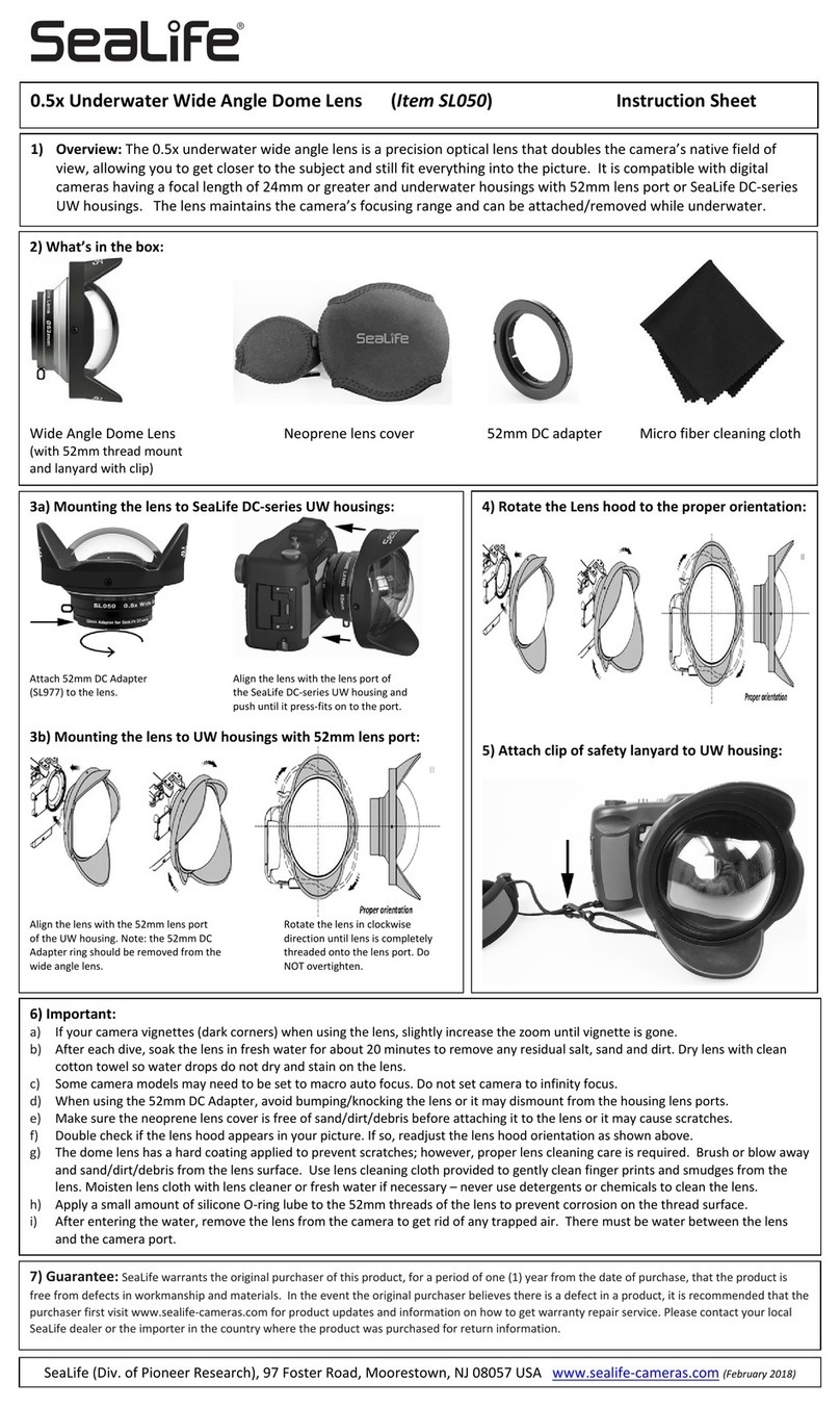
Mitsubishi Electric OL-XD8000EZ Guide

オプションレンズ
OL-XD8000EZ
レンズ取付要領書
ご不明な点がありましたら、販売店または三菱電機テクニカルサポートセンターにご相談ください。
● オプションレンズの取り付けは、必ず教育を受けた専門業者に依頼してください。
● レンズを取り付ける前にレンズシフトが工場出荷位置(またはレンズシフトリセット位置)であることを確認してください。
● レンズを取り付ける前には必ず電源スイッチを切り、電源プラグをコンセントから抜いてください。
オプションレンズの取り付けかた
以下の手順にしたがってオプションレンズを取り付けてください。
1. レンズカバーをはずす
2. レンズリングを反時計方向に少し回してはずす
3. トップカバーをとめているネジ(a)をはずす
4. トップカバーを矢印の方向に持ち上げて開ける
5. 標準レンズのズーム/フォーカスモーター用のコネクター(b)をはずす
6. ロックボタン(c)を押しながら、固定リング(d)を反時計方向に少し回して
7. レンズが落下しないようにレンズを支えながら、固定リング(d)を反時計方
ロックを解除する
向いっぱいまで回してレンズの固定を解除する
8. 標準レンズを矢印方向にはずす
方向に取り付ける(オプションレンズを取り付ける前にレンズキャップをは
オプションレンズをモーター ( e) が図のような位置になるようにして、矢印
ずしておくこと)
10.
11.オプションレンズのズーム/フォーカスモーター用のコネクターを取り付ける
固定リング(d)をロックが掛かる ( ロックボタン ( c) がカチッと音がして前
に出る ) まで回し、レンズを固定する
12.トップカバーをはずしたときと反対の手順で取り付ける
レンズリングのライン(f)を上にして挿入し、時計方向に回して取り付ける
13.ネジ(a)を締め付ける(プラスドライバーは軸の長さが150mm以上のものを使用し
てください)
14.
レンズ取り付け後の確認について
レンズ交換後は安全のため、必ず以下の事項をご確認ください。
● ズーム/フォーカスモーター用のコネクターがしっかりと差し込まれているか確認する。
● リード線が機械部品にはさみ込まれていないか確認する。
レンズ取り付け後の注意点
● レンズ取り付け後は、プロジェクター本体の輸送はしないでください。プロジェクター本体が破損するおそれがあります。
● レンズ取り付け後は、投写映像の明るさ、解像度、色均一性が標準レンズの場合と異なることがあります。
● レンズ取り付け後の台形補正は、補正角度の範囲が標準レンズ搭載時と異なります。
● レンズ取り付け後の台形補正は、画面が正しいアスペクト比にならないことがあります。
● 投写画面を右図の画面可動範囲の上端(天吊りの場合は下端)および左右端付近に設定した場合、画面の歪みが大きくなったり、解像度が低下したり、
画面隅に影が発生したりすることがあります。
● ズーム/フォーカス調整、レンズシフトロックについて、くわしくは、取扱説明書をご覧ください。
レンズシフト動作中はレンズ開口部に手などをはさまないよう、注意してください。
日本語
画面サイズと投写距離
仕様
F 値F2.4
焦点距離f=11.4〜14.2mm
ズーム/フォーカス電動
レンズカバー レンズリング
トップカバー
(a)
(c) (d)
(b)
(f)
(f)
オ プ ション レン ズ
レンズキャップ
(e)
XGA機種
WXGA機種
WUXGA機種
レンズの清掃方法
市販のレンズ手入れ用品(レンズ用のクリーニングペーパーまたは布、ブローワーブラシなど)でほこりや汚れを取ってください。
● レンズの表面は傷つきやすいので、かたいものでこすったり、たたいたりしないでください。
● アルコールを含んだレンズクリーナーや溶剤で拭かないでください。拭き後が付いたり、レンズコーティングが剥げてフォーカス性能に影響を与え
る場合があります。
● レンズを清掃するときは、必ずランプを消灯させ、レンズが十分に冷えた後に行ってください。
9. レンズリングをオプションレンズの先端付近まで通す
フォーカス補正機能について
OL-XD8000EZには画面中央と周辺のフォーカスバランスを補正するフォーカス
補正機能があります。
フォーカス調整のしかた
1.フォーカス補正リングを手で回し、中央の目盛りを基準線に合わせる
2.プロジェクター本体の操作で、画面のフォーカスを合わせる
通常は上記の調整で画面フォーカスが合いますが、オプションレンズとプロジェ
クターの個体差によっては画面中央と周辺のフォーカスバランスが異なる場合が
あります。
その場合は以下のように調整を行うと改善する場合があります。
1.フォーカス補正リングを時計方向、または反時計方向に手で回し、端の目盛り
を基準線に合わせる
2.プロジェクター本体の操作で、画面のフォーカスを合わせる
レンズリング
基準線
中央の目盛り
フォーカス補正リング
端の目盛り
画面サイズ(4:3) 投写距離L レンズシフト高さ レンズシフト幅
W1(cm)
形幅W
(cm)
高さH
(cm)
最短
(m)
最長
(m)
H1
(cm)
H2
(cm)
40 81 61 0.6 0.8 30 6 8
60 122 91 1.0 1.2 46 9 12
80 163 122 1.3 1.6 61 11 16
100 203 152 1.6 2.0 76 14 20
150 305 229 2.4 3.1 114 21 30
200 406 305 3.3 4.1 152 28 41
250 508 381 4.1 5.1 191 36 51
300 610 457 4.9 6.1 229 43 61
表の中の数値は、実際と数%誤差が生じることがあります。
L
L
W1W1
H1 H2
H
W
レンズ中心
画面可動範囲
画面サイズ(16:10) 投写距離L レンズシフト高さ レンズシフト幅
W1(cm)
形幅W
(cm)
高さH
(cm)
最短
(m)
最長
(m)
H1
(cm)
H2
(cm)
40 86 54 0.7 0.9 25 12 9
60 129 81 1.0 1.3 37 17 13
80 172 108 1.4 1.7 49 23 17
100 215 135 1.7 2.2 62 29 22
150 323 202 2.6 3.3 92 43 33
200 431 269 3.5 4.4 123 58 44
250 538 337 4.4 5.5 154 72 55
300 646 404 5.3 6.6 185 86 65
表の中の数値は、実際と数%誤差が生じることがあります。
L
L
W1W1
H1 H2
H
W
レンズ中心
画面可動範囲
画面サイズ(16:10) 投写距離L レンズシフト高さ レンズシフト幅
W1(cm)
形幅W
(cm)
高さH
(cm)
最短
(m)
最長
(m)
H1
(cm)
H2
(cm)
40 86 54 0.6 0.8 26 10 8
60 129 81 1.0 1.2 39 15 12
80 172 108 1.3 1.7 52 20 17
100 215 135 1.7 2.1 66 25 21
150 323 202 2.5 3.1 98 37 31
200 431 269 3.3 4.2 131 50 42
250 538 337 4.2 5.2 164 62 52
300 646 404 5.0 6.3 197 75 62
表の中の数値は、実際と数%誤差が生じることがあります。
L
L
W1W1
H1 H2
H
W
レンズ中心
画面可動範囲

OPTION LENS
OL-XD8000EZ
Lens Mounting Manual
rLens mounting must be performed by service personnel.
rCheck that the lens shift is at the factory default position (or the lens shift reset position) before mounting the option lens.
rBe sure to turn off the projector and unplug the power cord from the wall outlet before mounting the option lens.
Lens mounting procedure
Mount the option lens using the following procedure.
1. Remove the lens cover.
2. Turn the ring counterclockwise and remove it.
3. Remove the screw (a) securing the cover.
4. Open the cover by pulling it up in the direction of an arrow.
5. Release the connector (b) for the zoom/focus motor of the standard
lens.
6. While holding down the lock button (c), slightly turn the xed ring (d)
counterclockwise to release the lock.
7. While holding the lens to prevent it from falling, turn the xed ring (d)
fully counterclockwise to unlock the lens.
8. Remove the standard lens in the arrow’s direction.
9. Attach the lens ring on the tip of the option lens.
Attach the option lens in the arrow’s direction so that the motors (e)
are positioned as shown by the gure. (Remove the lens caps before
attaching the option lens.)
10. Turn the xed lens (d) until it is put into place (and the lock button (c)
clicks into place) to secure it.
11. Lock the connector for the zoom/focus motor of the option lens.
12. Mount the cover in the reverse order of removal.
13. Tighten up the screw (a).(Use a Phillips screwdriver having a shaft of
150 mm or longer.)
14. Mount the ring with the line (f) faced up and turn it clockwise.
Check after mounting the lens
After replacing the lens, be sure to check the following for ensuring safety.
rCheck that the connector for the zoom/focus motor is locked securely.
rCheck that no lead wires are caught in mechanical parts.
Cautions after mounting
rDo not transport the projector with the option lens mounted. The projector may be damaged.
rWith the option lens mounted, the brightness, resolution, and color uniformity in the projected image may differ from those with
the standard lens.
rWith the option lens mounted, the adjustable angle in the keystone adjustment differs from that with the standard lens.
rIn the keystone adjustment with the option lens mounted, the proper aspect ratio may not be obtained.
r
Projected images may become distorted, have decreased resolution, or have shadows at their corners if they are positioned close
to the top (or bottom in the case of a ceiling-mount projector) or right or left edge of the effective projection area shown on the right.
rFor details about ZOOM/FOCUS adjustment and LENS SHIFT LOCK, see User Manual of the projector.
Be careful not to caught in the opening in the lens while the lens is moving.
ENGLISH
(c) (d)
(b)
Lens cover
(a)
Top cover
(f)
(f)
(e)
Lens ring
Option lens
Specifications
F No. F2.4
Focal distance f = 11.4-14.2 mm
Zoom/focus Electric drive
872C580A10
When you have any inquiries, contact your dealer.
Lens cap
Lens ring
Reference line
Center scale
Focus correction ring
Edge scale
Cleaning of the lens
Remove dust or dirt using the commercially available lens care products (such as cleaning paper or cloth for lens and blower brush).
r4JODFUIFMFOTTVSGBDFJTTFOTJUJWFEPOPUTDSVCJUXJUIBTPMJEPCKFDUPSUBQPOJU
r%POPUXJQFUIFMFOTXJUIMFOTDMFBOFSPSTPMWFOUDPOUBJOJOHBMDPIPM%PJOHTPNBZDBVTFXJQFNBSLTPSQFFMPGGUIFMFOTDPBUJOH
and the focus performance may be affected.
r.BLFTVSFUPDMFBOUIFMFOTBGUFSUIFMBNQJTUVSOFEPGGBOEUIFMFOTJTDPPMFETVGGJDJFOUMZ
Focus correction function
OL-XD8000EZ has the focus correction function that corrects
the focus balance at and around the center of the screen.
Focus correction procedure
1. Align the center scale of the focus correction ring with the reference line.
2. Adjust the screen focus using the projector.
Normally, the screen focus is adjusted properly using the procedure
described above. However, the focus balance at and around the center of
the screen may be different depending on the characteristics of the lens
and the projector. In such a case, following the procedure described below
may improve the symptom.
1. Turn the focus correction ring clockwise or counterclockwise manually
and align the edge scale with the reference line.
2. Adjust the screen focus using the projector.
XGA model
Screen size (4:3) Projection distance (L) Lens shift height Lens shift
width
(W1)
Diagonal
size
Width
(W)
Height
(H)
Shortest
(Wide)
Longest
(Tele) H1 H2
inch cm inch cm inch cm inch m inch m inch cm inch cm inch cm
40 102 32 81 24 61 25 0.6 31 0.8 12 30 2 6 3 8
60 152 48 122 36 91 38 1.0 47 1.2 18 46 3 9 5 12
80 203 64 163 48 122 51 1.3 64 1.6 24 61 4 11 6 16
100 254 80 203 60 152 64 1.6 80 2.0 30 76 6 14 8 20
150 381 120 305 90 229 96 2.4 120 3.1 45 114 8 21 12 30
200 508 160 406 120 305 128 3.3 161 4.1 60 152 11 28 16 41
250 635 200 508 150 381 161 4.1 201 5.1 75 191 14 36 20 51
300 762 240 610 180 457 193 4.9 242 6.1 90 229 17 43 24 61
r5IF above numbers are approximate, and may be slightly different from the actual measurements.
L
L
W1W1
H1 H2
H
W
Center of the
lens
Maximum
projection area
WUXGA model
Screen size (16:10) Projection distance (L) Lens shift height Lens shift
width
(W1)
Diagonal
size
Width
(W)
Height
(H)
Shortest
(Wide)
Longest
(Tele) H1 H2
inch cm inch cm inch cm inch m inch m inch cm inch cm inch cm
40 102 34 86 21 54 25 0.6 32 0.8 10 26 4 10 3 8
60 152 51 129 32 81 39 1.0 49 1.2 15 39 6 15 5 12
80 203 68 172 42 108 52 1.3 65 1.7 21 52 8 20 7 17
100 254 85 215 53 135 65 1.7 82 2.1 26 66 10 25 8 21
150 381 127 323 79 202 98 2.5 123 3.1 39 98 15 37 12 31
200 508 170 431 106 269 131 3.3 165 4.2 52 131 20 50 16 42
250 635 212 538 132 337 165 4.2 206 5.2 65 164 24 62 20 52
300 762 254 646 159 404 198 5.0 248 6.3 77 197 29 75 25 62
r5IF above numbers are approximate, and may be slightly different from the actual measurements.
L
L
W1W1
H1 H2
H
W
Center of the
lens
Maximum
projection area
WXGA model
Screen size (16:10) Projection distance (L) Lens shift height Lens shift
width
(W1)
Diagonal
size
Width
(W)
Height
(H)
Shortest
(Wide)
Longest
(Tele) H1 H2
inch cm inch cm inch cm inch m inch m inch cm inch cm inch cm
40 102 34 86 21 54 27 0.7 34 0.9 10 25 5 12 3 9
60 152 51 129 32 81 41 1.0 51 1.3 15 37 7 17 5 13
80 203 68 172 42 108 55 1.4 68 1.7 19 49 9 23 7 17
100 254 85 215 53 135 68 1.7 86 2.2 24 62 11 29 9 22
150 381 127 323 79 202 103 2.6 129 3.3 36 92 17 43 13 33
200 508 170 431 106 269 138 3.5 173 4.4 49 123 23 58 17 44
250 635 212 538 132 337 173 4.4 216 5.5 61 154 28 72 21 55
300 762 254 646 159 404 208 5.3 260 6.6 73 185 34 86 26 65
r5IF above numbers are approximate, and may be slightly different from the actual measurements.
L
L
W1W1
H1 H2
H
W
Center of the
lens
Maximum
projection area
1 Zusho Baba, Nagaokakyo-City, Kyoto Japan
M
ITSUBISHI
ELECTRIC CORPORATIO
N

FRANÇAISFRANÇAIS
OBJECTIF EN OPTION
OL-XD8000EZ
Manuel de Montage de l’Objectif
Le montage de l’objectif doit.être effectuépar un technicien qualifié.
Vérifiez que le décalage de l’objectif est à la position usine par défaut (ou à la position de réinitialisation du décalage de
l’objectif), puis abaissez-le à la position la plus basse avant de monter l’objectif en option.
Veiller à ce que le projecteur soit éteint et à débrancher le cordon d’alimentation de la prise mulare avant de monter l’objectif en option.
Procedure de montage de l’objectif
Installer l’objectif en option en suivant la procédure ci-dessous.
1. Retirer le couvercle de l’objectif.
2. Tournez l’anneau dans le sens des aiguilles d’une montre et retirez le.
3. Retirez la vis (a) en maintenant le couvercle.
4. Ouvrir le couvercle en la tirant dans la direction d’une èche.
5. Libérez le connecteur (b) pour le moteur de zoom/mise au point de
l’objectif standard.
6.
En maintenant la touche de verrouillage (c) pressée, tournez légèrement la bague
xée (d) dans le sens contraire des aiguilles d’une montre pour débloquer.
7. En maintenant l’objectif pour éviter qu’il tombe, tournez la bague
xée (d) à fond dans le sens contraire des aiguilles d’une montre pour
débloquer l’objectif.
8. Retirez l’objectif standard dans le sens de la èche.
9. Attachez l’objectif en option dans le sens de la èche de sorte que les
moteurs (e) soient positionnés comme indiqué sur l’illustration.(Retirer
les caches de l’objectif avant de attacher l’objectif en option.)
10. Tournez l’objectif (d) xé jusqu’à l’immobilisation (le bouton de
verrouillage (c) cliquette).
11. Verrouillez le connecteur pour le moteur de zoom/mise au point de
l’objectif en option.
12. Montez le couvercle dans le sens inverse du démontage.
13. Fixez la vis (a).
(Utilisez un tournevis cruciforme ayant une tige de 150 mm ou plus.)
14. Montez l’anneau avec la ligne (f) de face et faites le tourner dans le sens
des aiguilles d’une montre.
Contrôle après le montage de l’objectif
Après le remplacement de l’objectif, vériez ce qui suit pour assurer la sécurité.
Vériez que le connecteur du moteur de zoom/mise au point est fermement verrouillé.
Vériez qu’aucun conducteur n’est coincé dans les pièces mécaniques.
Précautions après le montage
Ne transportez pas le projecteur avec la lentille en option xée. Cela pourrait endommager le projecteur.
Avec la lentille en option, la luminosité, résolution et l’uniformité des couleurs des images projetées peuvent être différentes des
lentilles standard.
Une fois l’objectif en option installé, l’angle réglable du réglage de trapèze varie par rapport à une projection avec l’objectif
standard uniquement.
Lorsque l’objectif en option est installé, il se peut que le format d’image ne soit pas correct.
Les images projetées peuvent être déformées, avec une résolution moins bonne, ou des ombres dans les coins s’ils sont
positionnés près du haut (ou du bas en cas de projecteur monté au plafond) ou sur le bord droite ou gauche de la zone de
projection efcace indiquée ci-contre.
Voir le Mode d’emploi du projecteur pour les détails sur le réglage ZOOM/FOCUS et VERROUILLAGE LENS SHIFT.
Evitez de vous coincer à l’ouverture de l’objectif quand l’objectif bouge.
Couvercle de
l’objectif
Couvercle
du dessus
Bague de
l’objectif
Bague de
l’objectif
Caches de
l’objectif
Objectif en option
Caractéristiques techniques
F N°. F2,4
Distance focale f = 11,4 - 14,2 mm
Zoom/mise au point Fonctionnement électrique
Taille de l’écran (4:3)
Distance de projection (L)
Hauteur de déplacement
de l’objectif
Largeur de
déplacement
de l’objectif
(W1)
Taille de la
diagonale
Largeur
(W)
Hauteur
(H)
Le plus
court (Large)
Le plus long
(Télescopique)
H1 H2
pouces
cm
pouces
cm
pouces
cm
pouces
m
pouces
m
pouces
cm
pouces
cm
pouces
cm
40 102 32 81 24 61 25 0,6 31 0,8 12 30 2 6 3 8
60 152 48 122 36 91 38 1,0 47 1,2 18 46 3 9 5 12
80 203 64 163 48 122 51 1,3 64 1,6 24 61 4 11 6 16
100 254 80 203 60 152 64 1,6 80 2,0 30 76 6 14 8 20
150 381 120 305 90 229 96 2,4 120 3,1 45 114 8 21 12 30
200 508 160 406 120 305 128 3,3 161 4,1 60 152 11 28 16 41
250 635 200 508 150 381 161 4,1 201 5,1 75 191 14 36 20 51
300 762 240 610 180 457 193 4,9 242 6,1 90 229 17 43 24 61
rLes chiffres indiqués ci-dessus peuvent être légèrement différents par rapport aux mesures réelles.
L
L
W1W1
H1 H2
H
W
Centre de
l’objectif
La zone de
projection maximum
XGA Modèle
WUXGA Modèle
WXGA Modèle
Taille de l’écran (16:10)
Distance de projection (L)
Hauteur de déplacement
de l’objectif
Largeur de
déplacement
de l’objectif
(W1)
Taille de la
diagonale
Largeur
(W)
Hauteur
(H)
Le plus
court (Large)
Le plus long
(Télescopique)
H1 H2
pouces
cm
pouces
cm
pouces
cm
pouces
m
pouces
m
pouces
cm
pouces
cm
pouces
cm
40 102 34 86 21 54 27 0,7 34 0,9 10 25 5 12 3 9
60 152 51 129 32 81 41 1,0 51 1,3 15 37 7 17 5 13
80 203 68 172 42 108 55 1,4 68 1,7 19 49 9 23 7 17
100 254 85 215 53 135 68 1,7 86 2,2 24 62 11 29 9 22
150 381 127 323 79 202 103 2,6 129 3,3 36 92 17 43 13 33
200 508 170 431 106 269 138 3,5 173 4,4 49 123 23 58 17 44
250 635 212 538 132 337 173 4,4 216 5,5 61 154 28 72 21 55
300 762 254 646 159 404 208 5,3 260 6,6 73 185 34 86 26 65
rLes chiffres indiqués ci-dessus peuvent être légèrement différents par rapport aux mesures réelles.
L
L
W1W1
H1 H2
H
W
Centre de
l’objectif
La zone de
projection maximum
Taille de l’écran (16:10)
Distance de projection (L)
Hauteur de déplacement
de l’objectif
Largeur de
déplacement
de l’objectif
(W1)
Taille de la
diagonale
Largeur
(W)
Hauteur
(H)
Le plus
court (Large)
Le plus long
(Télescopique)
H1 H2
pouces
cm
pouces
cm
pouces
cm
pouces
m
pouces
m
pouces
cm
pouces
cm
pouces
cm
40 102 34 86 21 54 25 0,6 32 0,8 10 26 4 10 3 8
60 152 51 129 32 81 39 1,0 49 1,2 15 39 6 15 5 12
80 203 68 172 42 108 52 1,3 65 1,7 21 52 8 20 7 17
100 254 85 215 53 135 65 1,7 82 2,1 26 66 10 25 8 21
150 381 127 323 79 202 98 2,5 123 3,1 39 98 15 37 12 31
200 508 170 431 106 269 131 3,3 165 4,2 52 131 20 50 16 42
250 635 212 538 132 337 165 4,2 206 5,2 65 164 24 62 20 52
300 762 254 646 159 404 198 5,0 248 6,3 77 197 29 75 25 62
rLes chiffres indiqués ci-dessus peuvent être légèrement différents par rapport aux mesures réelles.
L
L
W1W1
H1 H2
H
W
Centre de
l’objectif
La zone de
projection maximum
(c) (d)
(f)
(b)
(a)
r
r
r
r
r
r
r
r
r
r
r
Pour toute question, veuillez contacter votre revendeur.
Nettoyage de l’objectif
Retirez la poussière ou la saleté en utilisant des produits spécial verre vendus dans le commerce (comme une lingette nettoyante ou un tissu
spécial verre et une brosse soufeuse).
rEtant donné que la surface de la lentille est sensible, ne la rayez et ne a cognez pas avec un objet solide.
rN’essuyez pas la lentille avec un nettoyant ou un solvant pour lentilles contenant de l’alcool, sous peine de laisser des marques, d’écailler
le revêtement de la lentille et d’affecter les performances de mise au point.
rAprès avoir éteint la lampe, assurez-vous de nettoyer la lentille une fois qu’elle a sufsamment refroidi.
Fixez la bague de l'objectif sur l'extrémité de l'objectif en option.
Fonction de correction de la mise au point
OL-XD8000EZ possède la fonction de correction de la mise au point qui permet de
Procédure de correction de la mise au point
1. Alignez le centre de la règle graduée de la bague de correction de la mise au point avec la
ligne de référence.
2. Ajustez la mise au point de l'écran à l'aide du projecteur.
Normalement, la mise au point de l'écran est correctement réglée en suivant la procédure
décrite ci-dessus. Cependant, le réglage de la mise au point au centre de l'écran et autour
de celui-ci peut être différent selon les caractéristiques de l'objectif et du projecteur.
Dans un tel cas, suivez la procédure décrite ci-dessous qui pourra vous aider à améliorer
le symptôme.
1. Tournez manuellement la bague de correction de la mise au point dans le sens des
aiguilles d'une montre ou inversement et alignez la règle graduée avec la ligne de référence.
2. Ajustez la mise au point de l'écran à l'aide du projecteur.
Ligne de référence
Centre de la règle graduée
Bord de la règle graduée
Bague de correction
de la mise au point
corriger le réglage de la mise au point au centre de l'écran ou autour de ce dernier.
(f)
(e)

ZUSATZLINSE
OL-XD8000EZ
Handbuch zum Befestigen der Linse
Der Befestigen der linse muss durch den Kundendienst durchgeführt werden.
Stellen Sie sicher, dass sich der Linsenversteller in der im Werk voreingestellten Position (oder in der Linsenverstellungs-
Rückstellposition) befindet, bevor Sie die Linse befestigen.
Stellen Sie sicher, dass Sie den Projektor ausschalten und das Netzkabel abtrennen, bevor Sie die Linse befestigen.
Verfahren zum Befestigen der Linse
Befestigen Sie die Linse unter Durchführung des folgenden Verfahrens.
1. Entfernen Sie die Linsenabdeckung.
2.
Drehen Sie den Ring gegen den Uhrzeigersinn und nehmen Sie ihn ab.
3. Entfernen Sie Schraube
(a)
, welche Abdeckung befestigt.
4.
Öffnen Sie die Abdeckung durch Ziehen in Pfeilrichtung.
5.
Lösen Sie den Anschluss (b) zum Zoom/Fokussierungsmotor der Standardlinse.
6.
Während Sie die Sperrtaste (c) niedergedrückt halten, drehen Sie den Festring
(d) ein wenig entgegen dem Uhrzeigersinn, um die Sperre freizugeben.
7.
Während Sie die Linse halten, damit sie nicht herunterfällt, drehen Sie den
Festring (d) völlig entgegen dem Uhrzeigersinn, um die Linse zu lösen.
8. Entfernen Sie die Standardlinse in Pfeilrichtung.
Bringen Sie die Optionslinse in Pfeilrichtung an, so dass der Motoren
9. Bringen Sie den Objektivring an der Spitze des optionalen Objektivs an.
(e) wie in der Abbildung gezeigt positioniert sind. (Entfernen Sie die
Linsendeckel, bevor Sie die Optionlinse anbringen.)
10. Drehen Sie die feste Linse (d) bis sie ihren Platz einsitzt (bis die
Arretiertsate (c) einrastet), um sie zu sichern.
11. Verriegeln Sie den Anschluss zum Zoom/Fokussierungsmotor der
optionellen Linse.
12. Bringen Sie die Abdeckung an, indem Sie das Verfahren zum Entfernen
in umgekehrter Reihenfolge anwenden.
13. Ziehen Sie Schraube (a) fest.(Verwenden Sie einen
Kreuzschlitzschraubendreher mit einer Klinge von mindestens 150 mm.)
14.
Bringen Sie den Objektivring mit der Linie (f) nach oben an und drehen Sie ihn im
Uhrzeigersinn.
Überprüfen Sie, ob die Linse rightig eingebaut ist
Nach Auswechseln der Linse, überprüfen Sie unbedingt die folgenden
Punkte, um die Sicherheit zu gewähren.
Überprüfen Sie, ob der Anschluss zum Zoom/Fokussierungsmotor fest verriegelt ist.
Stellen Sie sicher, dass keine Leitungsdrähte in den beweglichen Teilen eingefangen sind.
Vorsichtsmassnahmen nach dem Befestigen
Transportieren Sie den Projektor nicht mit angebrachter optionaler Linse. Der Projektor könnte beschädigt werden.
Wenn die optionale Linse angebracht wurde, weichen u.U. Helligkeit, Auösung und Farbkonstanz des projizierten Bildes von den
Werten der Standardlinse ab.
Der einstellbare Winkel unter der Trapezkorrektur-Einstellung kann sich nach der Befestigung der optionalen Linse von dem mit
einer Standard-Linse unterscheiden.
Wird nach der Befestigung der optionalen Linse eine Trapezkorrektur durchgeführt, kann das korrekte Seitenverhältnis ggf. nicht
beibehalten werden.
Die projektierten Bilder könnten verzerrt erscheinen, eine verminderte Auösung haben oder Schatten an den Ecken aufzeigen,
wenn sie nahe zum oberen Rand (bzw. unterem Rand bei einem Deckenprojektor) oder nahe zum rechten oder linken Rand der
effektiven Projektionsäche wie rechts gezeigt positioniert werden.
Nähere Einzelheiten über die ZOOM/FOCUS-Einstellung und LENS SHIFT LOCK nden Sie in der Betriebsanleitung für den Projektor.
Vorsicht, damit Sie sich in der Objektivöffnung nicht verfangen wenn sich das Objektiv bewegt.
DEUTSCHDEUTSCH
Linsenabdeckung Obere
Abdeckung
Ringlinse
Ringlinse
Linsendeckel
Optionale Linse
Größe der Leinwand (16:10)
Abstand der Projektionswand (L)
Linsenverschiebungs-Höhe
Linsen-
verschiebungs-
Breite (W1)
Diagonale Breite
(W)
Höhe
(H)
Am kürzesten
(Breit)
Am längsten
(Teleskop)
H1 H2
Zoll cm Zoll cm Zoll cm Zoll m Zoll m Zoll cm Zoll cm Zoll cm
40 102 34 86 21 54 25 0,6 32 0,8 10 26 4 10 3 8
60 152 51 129 32 81 39 1,0 49 1,2 15 39 6 15 5 12
80 203 68 172 42 108 52 1,3 65 1,7 21 52 8 20 7 17
100 254 85 215 53 135 65 1,7 82 2,1 26 66 10 25 8 21
150 381 127 323 79 202 98 2,5 123 3,1 39 98 15 37 12 31
200 508 170 431 106 269 131 3,3 165 4,2 52 131 20 50 16 42
250 635 212 538 132 337 165 4,2 206 5,2 65 164 24 62 20 52
300 762 254 646 159 404 198 5,0 248 6,3 77 197 29 75 25 62
rDie o, g, Werte sind Näherungswerte und können von den aktuellen Meßwerten abweichen.
L
L
W1W1
H1 H2
H
W
Mitte der
Linse
Maximaler
Projektionsbereich
Größe der Leinwand (16:10)
Abstand der Projektionswand (L)
Linsenverschiebungs-Höhe
Linsen-
verschiebungs-
Breite (W1)
Diagonale Breite
(W)
Höhe
(H)
Am kürzesten
(Breit)
Am längsten
(Teleskop)
H1 H2
Zoll cm Zoll cm Zoll cm Zoll m Zoll m Zoll cm Zoll cm Zoll cm
40 102 34 86 21 54 27 0,7 34 0,9 10 25 5 12 3 9
60 152 51 129 32 81 41 1,0 51 1,3 15 37 7 17 5 13
80 203 68 172 42 108 55 1,4 68 1,7 19 49 9 23 7 17
100 254 85 215 53 135 68 1,7 86 2,2 24 62 11 29 9 22
150 381 127 323 79 202 103 2,6 129 3,3 36 92 17 43 13 33
200 508 170 431 106 269 138 3,5 173 4,4 49 123 23 58 17 44
250 635 212 538 132 337 173 4,4 216 5,5 61 154 28 72 21 55
300 762 254 646 159 404 208 5,3 260 6,6 73 185 34 86 26 65
rDie o, g, Werte sind Näherungswerte und können von den aktuellen Meßwerten abweichen.
L
L
W1W1
H1 H2
H
W
Mitte der
Linse
Maximaler
Projektionsbereich
WUXGA Modell
WXGA Modell
XGA Modell
Technische Daten
F-Nr. F2,4
Fokus-Abstand f = 11,4 - 14,2 mm
Zoom/Fokus Elektrischer Antrieb
Größe der Leinwand (4:3)
Abstand der Projektionswand (L)
Linsenverschiebungs-Höhe
Linsen-
verschiebungs-
Breite (W1)
Diagonale Breite
(W)
Höhe
(H)
Am kürzesten
(Breit)
Am längsten
(Teleskop)
H1 H2
Zoll cm Zoll cm Zoll cm Zoll m Zoll m Zoll cm Zoll cm Zoll cm
40 102 32 81 24 61 25 0,6 31 0,8 12 30 2 6 3 8
60 152 48 122 36 91 38 1,0 47 1,2 18 46 3 9 5 12
80 203 64 163 48 122 51 1,3 64 1,6 24 61 4 11 6 16
100 254 80 203 60 152 64 1,6 80 2,0 30 76 6 14 8 20
150 381 120 305 90 229 96 2,4 120 3,1 45 114 8 21 12 30
200 508 160 406 120 305 128 3,3 161 4,1 60 152 11 28 16 41
250 635 200 508 150 381 161 4,1 201 5,1 75 191 14 36 20 51
300 762 240 610 180 457 193 4,9 242 6,1 90 229 17 43 24 61
rDie o, g, Werte sind Näherungswerte und können von den aktuellen Meßwerten abweichen.
L
L
W1W1
H1 H2
H
W
Mitte der
Linse
Maximaler
Projektionsbereich
(c) (d)
(b)
(f)
(f)
(e)
(a)
Referenzlinie
Mittlere Skalierung
Fokuskorrekturring
Randskalierung
r
r
r
r
r
r
r
r
r
r
r
Wenn Sie Fragen haben, wenden Sie sich an Ihren Händler.
Fokuskorrekturfunktion
Das Modell OL-XD8000EZ verfügt über die Fokuskorrekturfunktion, mit der
die Bildschärfe in der bzw. um die Mitte der Projektionsfläche ausgeglichen
werden kann.
Fokuskorrekturverfahren
1. Richten Sie die mittlere Skalierung des Fokuskorrekturrings an der Referenzlinie aus.
2. Stellen Sie die Projektionsflächenbildschärfe am Projektor ein.
Normalerweise kann die Projektionsflächenbildschärfe mit dem oben
beschriebenen Verfahren korrekt angepasst werden. Je nach Eigenschaften von
Objektiv und Projektor kann der Bildschärfeausgleich in der bzw. um die Mitte
der Projektionsfläche jedoch abweichen. Falls diese Erscheinung auftritt, kann
der Zustand eventuell mit dem unten beschriebenen Verfahren verbessert werden.
1. Drehen Sie den Fokuskorrekturring von Hand im Uhrzeigersinn oder gegen den
Uhrzeigersinn und richten Sie die Randskalierung an der Referenzlinie aus.
2. Stellen Sie die Projektionsflächenbildschärfe am Projektor ein.
Reinigen des Objektivs
Entfernen Sie Staub oder Schmutz mit kommerziell erhältlichen Linsen-Pegemitteln (z. B. Reinigungspapier oder Stoff für die Linse und Luftpinsel).
r
Da die Oberäche der Linse empndlich ist, scheuern Sie diese niemals mit einem festen Gegenstand und klopfen Sie auch niemals darauf.
rWischen Sie das Brillenglas nicht mit Alkohol enthaltendem Brillenglasreiniger oder Lösungsmittel ab. Dadurch können Wischspuren
verursacht oder die Glasvergütung beschädigt werden, und die Fokussierleistung kann beeinträchtigt werden.
r
Reinigen Sie immer die Linse, nachdem die Lampe ausgeschaltet wurde und die Linse ausreichend abgekühlt ist.
872C580A20
1 Zusho Baba, Nagaokakyo-City, Kyoto Japan
M
ITSUBISHI
ELECTRIC CORPORATIO
N

选购镜头
OL-XD8000EZ
镜头安装手册
•必须由维修人员安装选购镜头。
•安装选购镜头前,检查镜头平移位于厂家的缺省位置(或者位于镜头平移原始位置)。
•安装选购镜头前,确保关闭投影机并且从墙上拔下电源线。
镜头安装程序
根据以下程序安装选购镜头。
1. 拔下镜头盖。
2. 逆时针转动镜头环,并将其拆下。
3. 拆除用于固定顶盖的螺丝 (a)。
4. 按照箭头所示的方向拉起顶盖,使其开启。
5. 松开标准透镜放大/焦距电机的连接器(b)。
6. 向下按锁定按扭(c)的同时,轻轻地以逆时针方向旋转固定环
(d),以解锁。
7. 握住透镜,防止透镜掉下的同时,逆时针方向旋转固定环
(d),以释放透镜。
8. 以镜头所示方向拆除标准透镜。
以箭头所示方向装上镜头,以便电机(e)定位如图所示。
9. 将透镜圈安装到选购镜头前端。
(安装选购镜头前,拔下镜头罩。)
10.旋转固定镜头(d),直到固定镜头就位(锁定按钮(c)发出
滴嗒的响声,并定位)以固定镜头。
11.锁定镜头放大/焦距电机的连接器。
12.按照和拆除时相反的程序装上顶盖。
13.拧紧螺丝 (a)。(请使用杆长至少为 150 mm 的 Phillips 螺丝刀。)
14.使标线 (f) 朝向上方,装上镜头环,并将其按顺时针转动。
安装镜头后进行检查
镜头定位后,检查以下项目,确保安全。
•检查放大/焦距电机连接器牢牢锁定。
•检查机械零件部分没有夹住任何导线。
安装镜头后的注意事项
•不要在镜头安装的情况下,运输投影机。否则,会损坏投影机。
•安装选购镜头的情况下,投影图像的亮度、分辨度以及颜色匀称性与安装标准镜头时不同。
•安装选购镜头的情况下,关键调整部分的可调角度与只安装标准镜头时不同。
•安装选购镜头的情况下,在关键调整时,可能得不到理想的纵横比。
•投影的图像可能会扭曲、分辨率会下降、或者当如右图所示,将其投影至有效投影区域的最上方(如果为吸顶
投影机时,为最底部)、右侧或者左侧边缘时,会出现阴影。
•关于调整放大/焦距和镜头漂移锁的详细情况,见投影机用户手册。
小心,移动镜头时,不要将其卡在镜头开口处。
镜头盖
上顶盖
透镜圈
透镜圈
镜头罩
选购镜头
中文
日本国兵库印刷
2012.12
872C580A30
规格
F 值 F2.4
焦距 f = 11.4 - 14.2 毫米
变焦/聚焦 电子驱动
投影图像的尺寸(4:3) 投影距离 (L) 镜头移动高度
镜头移动宽度
对角尺寸 宽度 (W) 高度 (H) 最短
(广角)
最长
(望远) H1 H2 移动距离
(W1)
英寸 厘米 英寸 厘米 英寸 厘米 英寸 米 英寸 米 英寸 厘米 英寸 厘米 英寸 厘米
40 102 32 81 24 61 25 0.6 31 0.8 12 30 2 6 3 8
60 152 48 122 36 91 38 1.0 47 1.2 18 46 3 9 5 12
80 203 64 163 48 122 51 1.3 64 1.6 24 61 4 11 6 16
100 254 80 203 60 152 64 1.6 80 2.0 30 76 6 14 8 20
150 381 120 305 90 229 96 2.4 120 3.1 45 114 8 21 12 30
200 508 160 406 120 305 128 3.3 161 4.1 60 152 11 28 16 41
250 635 200 508 150 381 161 4.1 201 5.1 75 191 14 36 20 51
300 762 240 610 180 457 193 4.9 242 6.1 90 229 17 43 24 61
• 以上数字均为近似值,与实际测量值可能会稍有出入。
L
L
W1W1
2H1H H
W
透镜的中央
最大投影图像区域
XGA 型号
WUXGA 型号
WXGA 型号
投影图像的尺寸(16:10) 投影距离 (L) 镜头移动高度
镜头移动宽度
对角尺寸 宽度 (W) 高度 (H) 最短
(广角)
最长
(望远) H1 H2 移动距离
(W1)
英寸 厘米 英寸 厘米 英寸 厘米 英寸 米 英寸 米 英寸 厘米 英寸 厘米 英寸 厘米
40 102 34 86 21 54 25 0.6 32 0.8 10 26 4 10 3 8
60 152 51 129 32 81 39 1.0 49 1.2 15 39 6 15 5 12
80 203 68 172 42 108 52 1.3 65 1.7 21 52 8 20 7 17
100 254 85 215 53 135 65 1.7 82 2.1 26 66 10 25 8 21
150 381 127 323 79 202 98 2.5 123 3.1 39 98 15 37 12 31
200 508 170 431 106 269 131 3.3 165 4.2 52 131 20 50 16 42
250 635 212 538 132 337 165 4.2 206 5.2 65 164 24 62 20 52
300 762 254 646 159 404 198 5.0 248 6.3 77 197 29 75 25 62
• 以上数字均为近似值,与实际测量值可能会稍有出入。
L
L
W1W1
H1 H2
H
W
透镜的中央
最大投影图像区域
投影图像的尺寸(16:10) 投影距离 (L) 镜头移动高度
镜头移动宽度
对角尺寸 宽度 (W) 高度 (H) 最短
(广角)
最长
(望远) H1 H2 移动距离
(W1)
英寸 厘米 英寸 厘米 英寸 厘米 英寸 米 英寸 米 英寸 厘米 英寸 厘米 英寸 厘米
40 102 34 86 21 54 27 0.7 34 0.9 10 25 5 12 3 9
60 152 51 129 32 81 41 1.0 51 1.3 15 37 7 17 5 13
80 203 68 172 42 108 55 1.4 68 1.7 19 49 9 23 7 17
100 254 85 215 53 135 68 1.7 86 2.2 24 62 11 29 9 22
150 381 127 323 79 202 103 2.6 129 3.3 36 92 17 43 13 33
200 508 170 431 106 269 138 3.5 173 4.4 49 123 23 58 17 44
250 635 212 538 132 337 173 4.4 216 5.5 61 154 28 72 21 55
300 762 254 646 159 404 208 5.3 260 6.6 73 185 34 86 26 65
• 以上数字均为近似值,与实际测量值可能会稍有出入。
L
L
W1W1
H1 H2
H
W
透镜的中央
最大投影图像区域
基准线
中心刻度
焦距校正圈
边缘刻度
若有任何不明之处,请与您的经销商联系。
焦距校正功能
OL-XD8000EZ 拥有焦距校正功能,可以校正屏幕中心及附近的焦距平衡。
焦距校正步骤
1. 将焦距校正圈的中心刻度与基准线对齐。
2. 使用投影机调节屏幕焦距。
正常情况下,屏幕焦距可以通过上述步骤得到适当调节。
不过,屏幕中心及附近的焦距平衡可能因镜头和投影机特性而异。
在此情况下,按以下步骤操作可予以改善。
1. 沿顺时针或逆时针方向手动转动焦距校正圈,将边缘刻度与基
准线对齐。
2. 使用投影机调节屏幕焦距。
清洁镜头
请使用市售的镜头保护用品(例如:用于镜头的清洁纸、清洁布以及吹气刷)来清除镜头上的灰尘或污垢。
• 镜头表面十分容易被划伤,请勿用硬物刮、敲镜头。
• 不得使用含酒精的镜头清洁用品或溶剂擦拭镜头。否则会导致擦痕或镜头涂层脱落,而且可能会影响对焦性能。
• 确保在灯关闭且镜头已充分冷却之后清洁镜头。
(f)
(b)
(f)
(e)
(a)
(d)
(c)
1 Zusho Baba, Nagaokakyo-City, Kyoto Japan
M
ITSUBISHI
ELECTRIC CORPORATIO
N

1 Zusho Baba, Nagaokakyo-City, Kyoto Japan
M
ITSUBISHI
ELECTRIC CORPORATION
Mitsubishi Projector Warranty, Sales Support and Service Information
North America
MEVSA (Mitsubishi Electric Visual Solutions America, Inc.)
Presentation Products Division
9351 Jeronimo Road
Irvine CA 92618, USA
For Warranty Registration, visit:
http://www.mitsubishi-presentations.com under Customer Care
Sales & Inquiries
Phone :Toll Free (888)307-0349
Technical Inquiries
Phone :Toll Free (888)307-0309
MESCA (Mitsubishi Electric Sales Canada Inc.)
http://www.mitsubishielectric.ca
Information Technologies Group, 4299 14th Avenue,
Markham, Ontario L3R 0J2, Canada
Sales & Technical Inquiries
Phone :+1-(800) 450-6487
Fax :+1-(905) 475-7958
Customer Care
Europe
MEU-FRA (Mitsubishi Electric Europe B.V French Branch)
25, Boulevard des Bouvets 92 741, Nanterre CEDEX,
France
Sales Inquiries
Phone :+33 (0)1 55-68-55-53
Fax :+33 (0)1 55-68-57-31
Technical Inquiries
Phone :+33 (0)1 55-68-56-42
Fax :+33 (0)1 55-68-57-31
MEU-GER (Mitsubishi Electric Europe B.V. German Branch)
http://www.mitsubishi-evs.de/
Gothaer Strasse 8, 40880 Ratingen, Germany
Sales Inquiries
Phone :0049 - 2102 - 486 9250
Fax :0049 - 2102 - 486 7320
Technical Inquiries
Phone :0049 - 2102 - 486 1330
Fax :0049 - 2102 - 486 1340
MEU-IR (Mitsubishi Electric Europe B.V. Irish Branch)
http://www.mitsubishi.ie/
Westgate Business Park, Ballymount, Dublin 24, Ireland
Sales Inquiries
Phone :+353-1-4198807
Fax :+353-1-4198890
Technical Inquiries
Phone :+353-1-4198808
Fax :+353-1-4198895
MEU-IT (Mitsubishi Electric Europe B.V. Italian Branch)
Centro Direzionale Colleoni, Palazzo Sirio, Viale Colleoni 7,
20041 Agrate Brianza, Italy
Sales & Technical Inquiries
Phone :+39-(0)39-60531
Fax :+39-(0)39-6053214
MEU-NL (Mitsubishi Electric Europe B.V. Benelux Branch)
http://www.mitsubishielectric.nl/
Nijverheidsweg 23A, 3641 RP Mijdrecht, The Netherlands
Sales Inquiries
Phone :+31-297-282461
Fax :+31-297-283936
Technical Inquiries
Phone :+31-297-282461
Fax :+31-297-283936
Russia (Mitsubishi Electric Europe B.V Moscow
Representative Ofce)
http://www.mitsubishi-projector.ru/
Moscow Representative Ofce, 52/5 Kosmodamianskaya
Nab., 115054, Moscow, Russia
Sales & Technical Inquiries
Phone :(7095) 721-2068
Fax :(7095) 721-2071
MEU-SP (Mitsubishi Electric Europe B.V. Spanish Branch)
http://www.mitsubishielectric.es/
Ctra. de Rubi, 76-80, 08173 Sant Cugat del Valles,
Barcelona, Spain
Sales Inquiries
Phone :+34-93.565.31.54
Fax :+34-93.589.43.88
Technical Inquiries
Phone :+34-93.586.27.51
Fax :+34-93.588.53.87
MEU-SWE (Mitsubishi Electric Europe B.V Scandinavian
Branch)
Hammarbacken 14, Box 750, S-19127, Sollentuna, Sweden
Sales Inquiries
Phone :+46-(0)8-6251070
Fax :+46-(0)8-6251036
Technical Inquiries
Phone :+46-(0)8-6251052
Fax :+46-(0)8-6251036
MEU-UK (Mitsubishi Electric Europe)
http://vis.mitsubishielectric.co.uk/products/projectors/
Visual Information Systems Division, Travellers Lane,
Hateld, Hertfordshire, AL10 8XB U.K.
Sales Inquiries
Phone :+44 (1707) 278684
Fax :+44 (1707) 278541
Technical Inquiries
Phone :+44 (870) 606 5008
Fax :+44 (1506) 431927
Asia
CHINA (Mitsubishi Electric Air-Conditioning & Visual
Information Systems (Shanghai) Ltd.)
15/F Henderson Metropolitan, No. 300 East Nanjing Road,
Shanghai 200001, China
Sales & Technical Inquiries
Phone :+86(21)2312-3030 (Ext.3228)
Fax :+86(21)2312-3008
Sale and Service hotline
Phone :+86-400-820-2130
HONG KONG (Mitsubishi Electric Ryoden Air-Conditioning
& Visual Information Systems (HongKong) Ltd.)
9/F, Skyline Tower, 39 Wang Kwong Road, Kowloon Bay,
Kowloon, Hong Kong
Sales Inquiries
Phone :+852-2510-1505
Fax :+852-2510-0463
Technical Inquiries
Phone :+852-2422-0161
Fax :+852-2487-0181
SINGAPORE (Mitsubishi Electric Asia Pte. Ltd.)
http://www.mitsubishielectric.com.sg
307, Alexandra Road, #05-01/02 Mitsubishi Electric
Building, Singapore 159943
Sales Inquiries
Phone :+65-6473-2308
Fax :+65-6475-9503
Technical Inquiries
Phone :+65-6470-2666
Fax :+65-6475-9503
INDIA (Mitsubishi Electric Asia Pte. Ltd.)
307, Alexandra Road, #05-01/02 Mitsubishi Electric
Building, Singapore 159943
Sales Inquiries
Phone :+65-6473-2308
Fax :+65-6475-9503
Technical Inquiries
Phone :+65-6470-2666
Fax :+65-6475-9503
INDONESIA (Mitsubishi Electric Asia Pte. Ltd.)
307, Alexandra Road, #05-01/02 Mitsubishi Electric
Building, Singapore 159943
Sales Inquiries
Phone :+65-6473-2308
Fax :+65-6475-9503
Technical Inquiries
Phone :+65-6470-2666
Fax :+65-6475-9503
PHILIPPINES (Mitsubishi Electric Asia Pte. Ltd.)
http://www.mitsubishielectric.com.sg
307, Alexandra Road, #05-01/02 Mitsubishi Electric
Building, Singapore 159943
Sales Inquiries
Phone :+65-6473-2308
Fax :+65-6475-9503
Technical Inquiries
Phone :+65-6470-2666
Fax :+65-6475-9503
VIETNAM (Mitsubishi Electric Asia Pte. Ltd.)
307, Alexandra Road, #05-01/02 Mitsubishi Electric
Building, Singapore 159943
Sales Inquiries
Phone :+65-6473-2308
Fax :+65-6475-9503
Technical Inquiries
Phone :+65-6470-2666
Fax :+65-6475-9503
STC (Setsuyo Astec Corporation Seoul Branch)
16F KT Bldg., 28-2 Yeouido-dong, Yeoungdeungpo-gu,
Seoul 150-931, Korea
Sales & Technical Inquiries
Phone :+82-1588-5576
Fax :+82-2-704-8666
MALAYSIA (Melco Sales Malaysia Sdn Bhd)
Lot 11, Jalan 219, 46100 Petaling Jaya, Selangor Darul
Ehsan, Malaysia
Sales & Technical Inquiries
Phone :+60-(0)3-79573428
Fax :+60-(0)3-79563950/+60-(0)3-79582576
Technical & Service Inquiries
Phone :+60-(0)3-79553997
Fax :+60-(0)3-79584836
ME-TWN (Mitsubishi Electric Taiwan Co., Ltd.)
http://www.MitsubishiElectric.com.tw
11TH FL., 90 SEC. 6, CHUNG SHAN N. RD., TAIPEI, 111
R.O.C.
Sales & Technical Inquiries
Phone :+886-2-2832-8255
Fax :+886-2-2833-9813
MKY (Mitsubishi Electric Kang Yong Watana Co., Ltd. )
http://www.mitsubishi-kyw.co.th/
Road, Huamark Bangkapi, Bangkok 10240, Thailand
Sales & Technical Inquiries
Phone :+66-2-731-6841
Fax :+66-2-379-4763
Oceania
ME-AUST (Mitsubishi Electric Australia)
http://www.mitsubishielectric.com.au/163.htm
348 Victoria Road, Rydalmere, N.S.W. 2116, Australia
Sales & Technical Inquiries
Phone :+(612)9684-7777
Fax :+(612)9684-7208
Technical Inquiries
Phone :+(612)9684-7694
Fax :+(612)9684-7684
BDT (Black Diamond Technologies Ltd.)
(Warranty Registration) http://www.bdt.co.nz/projectors/
warranty.asp
1 Parliament St, Lower Hutt, Wellington, New Zealand
Sales Inquiries
Phone :+64-(0)4-560-9100
Fax :+64-(0)4-560-9133
Technical Inquiries
Phone :+64-(0)4-560-9100
Fax :+64-(0)4-560-9133
Table of contents
Languages:
Other Mitsubishi Electric Lens manuals
Popular Lens manuals by other brands

Bausch & Lomb
Bausch & Lomb ULTRA PATIENT INFORMATION BOOKLET

Vivitar
Vivitar 500MR F/6.3 instruction manual

Sony
Sony VCL-MHG07 - HIGH GRADE 0.7X WIDE-ANGLE LENS operating instructions

Panasonic
Panasonic Lumix H-FS14140 owner's manual

APEXEL
APEXEL 20-40XJJ04 user manual

Fantasea Line
Fantasea Line SEL30M35 instruction manual