Mitsubishi Electric MAC-558IF-E User manual

1
INSTALLATION GUIDE

2
Setting information
MAC-558IF address(MAC)
MAC-558IF serial number(ID)
MAC-558IF code(PIN)
Indoor unit model name
Indoor unit serial number
Outdoor unit model name
Outdoor unit serial number
System commissioning date
MAC-558IF installation date
Installer contact details
Name
Telephone number
Wi-Fi Control minimum requirements for operation.
• Compatible WPS capable wireless network with coverage
including the heat pump installation location
• A PC/Tablet/Smartphone that is iOS/Android/Windows
compatible
• A compatible Mitsubishi Electric Heat Pump with a
MAC-558IF-E Adaptor

3
Once registered you will be able to control your heat pump with your
smartphone, tablet or online using an internet connection (for a list of
compatible devices please visit our website).
User Manual
A copy of the user manual, terms & conditions and our
privacy policy can be downloaded at any time from:
Mitsubishi Electric Wi-Fi Heat Pump Control
Register Your Heat Pump(s)
Thank you for choosing a Mitsubishi Electric Designer Series Heat Pump
with Wi-Fi Control. Once your adaptor is installed either download the
app (search term: Mitsubishi Control) or visit our website to register
your heat pump(s).
Need more help?
If you have any questions please contact us on:
0800 639 434 – Our customer support team is
available 8.30am - 5.00pm Monday to Friday.
www.facebook.com/MitsubishiElectricNZ
www.mitsubishi-electric.co.nz/wifi

4
The following steps explain how to connect the MAC-558IF-E
Adaptor to a Mitsubishi Electric Designer Series Heat Pump.
Wi-Fi Control: Installation Instructions
Information for installers
EQUIPMENT REQUIRED FOR INSTALL:
INSTALLATION GUIDE
MAC-558IF-E
Adaptor
WPS Enabled
Router
Wi-Fi
Installation
Guide
Tools to remove
cover of indoor
unit
#2 Phillips
Important Note: Before going to the users home ensure they
have a WPS enabled router and understand how to activate
WPS mode, otherwise this install will not work.
Record the adaptor’s MAC, ID
number and serial number on page
2 of the Wi-Fi Installation Guide.
Isolate the outdoor unit and verify
power has been disconnected to the
complete air conditioning system.
12

5
Run the cables down the back of
the unit with the other cables. Tuck
cabling away and secure.
Reassemble the air conditioning
unit and restore power to the
system.
Check that the MAC-558IF is
flashing. The install has now
been completed.
The adaptor is now able to be
connected to the user’s router.
Steps for this are shown on the
following pages.
65
7 8
Remove the cover of the indoor
unit, the cable terminal, and the
cover to the control unit board.
Locate the CN105 port on the
main control board and connect
MAC-558IF.
3 4

6
Wi-Fi Control: Installation Instructions
Information for users
The following steps explain how to connect the MAC-558IF-E
Adaptor to a router.
KEY (LED LIGHTS):
ON OFF FLASHING
Check Wi-Fi and WPS are enabled
on your router. Connection
procedure varies depending on
your router – refer to router manual
for more information.
Activate WPS on your router.
This will be enabled for a set
period allowing approximately two
minutes to complete Step 3.
Activate WPS on your adaptor by
using a small object to press and hold
the WPS button for two seconds.
Turn the adaptor over and check
LED 1 (top light) is flashing.
12
3 4

7
When LED 1 remains solid for 5
seconds the adaptor is connecting
to your router.
Next, the bottom light (LED 3) will
start flashing as it connects to the
internet. This may continue for up
to 10 minutes.
When LED 1 and LED 3 flash
alternately the unit is successfully
connected to the internet.
If LED 2 (orange) lights up at any
stage there may be a problem.
Check the troubleshooting section
on page 11.
You can now download the
Mitsubishi Control App and control
your heat pump via Wi-Fi.
6
9
5
7 8

8
1. Safety Instructions
• Read all safety instructions before using the
Wi-Fi adaptor.
• This installation manual contains important
safety information. Be sure to comply with
the instructions.
• After installing the Wi-Fi adaptor, provide
this installation manual for the user. Instruct
users to store it with their room air conditioner
instruction manual in a safe location.
1.Safety Instructions..........................................................................................8
2.Product Introduction .......................................................................................9
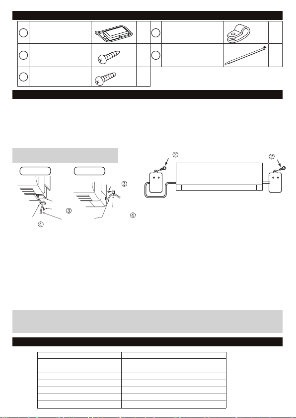
3. Parts .............................................................................................................10
4.Connecting the Wi-Fi adaptor.......................................................................10
5.Specications ...............................................................................................10
6.LED pattern ..................................................................................................11
7.Troubleshooting ............................................................................................11
8. Switch Function ............................................................................................11
Contents
About the Wi-Fi Adaptor
This Wi-Fi adaptor will communicate status information and control the connected air conditioner.
The Wi-Fi Access Point or Wireless Router must have a WPS function.
Warning
(Improper handling may have serious consequences, including serious injury or death.)
• Users should not install the adaptor on
their own.
• Improper installation may result in fire, electric
shock, or damage/water leaks. Consult the
dealer from whom you purchased the unit or
professional installer.
• The adaptor should be securely installed in
accordance with this installation manual.
• Improper installation may result in fire, electric
shock, or damage.
• The unit should be mounted in a location that can
support its weight.
• If the unit is installed in a location that cannot
support its weight, the Wi-Fi adaptor could fall
and cause damage.
• Connect and fasten the electric wires securely
so external force on the wires will not apply on
the terminals.
• Improper connection and mounting may result in
breakdown, heat generation, smoke generation,
or fire.
• Mitsubishi Electric components or other designated
components must be used for installation.
• Improper component may result in fire, electric
shock, or damage/water leaks.
• Electrical work must be performed by a licensed
professional using the instructions detailed in the
installation manual.
• Inadequate circuit capacity or improper
installation may result in electric shock or fire.
• This appliance is not intended for use by
persons (including children) with reduced
physical, sensory or mental capabilities, or lack
of experience and knowledge, unless they have
been given supervision or instruction concerning
use of the appliance by a person responsible for
their safety.
• Children should be supervised to ensure that they
do not play with the appliances.
• This device complies with all Australia and
New Zealand requirements for EMC and
electrical safety.
• Do not connect the Wi-Fi adaptor to earth inside
the air conditioner.
• Some room air conditioners are not compatible with the Wi-Fi adaptor. Make sure that the room
air conditioner is compatible with the Wi-Fi adaptor before attempting to install the Wi-Fi adaptor.

9
Caution
(Improper handling may have consequences, including injury or damage to house.)
• To prevent damage from static electricity, touch a
nearby metal body to discharge static electricity
from yourself before touching the Wi-Fi adaptor.
• Static electricity from the human body may
damage the Wi-Fi adaptor unit.
• Do not install the Wi-Fi adaptor in a place with
much steam, such as bathroom.
• Avoid places where water is splashed or where
condensation forms on walls. Installing in such
places can cause electric shock or breakdown.
• Do not install the Wi-Fi adaptor in places
with direct sunlight or where the ambient
temperature is 40ºC or more or is 0ºC or less.
Direct sunlight and high or low temperature
environments may cause the Wi-Fi adaptor to
deform or breakdown.
• Do not use in special environments.
• Do not use in places with much oil (including
machine oil), steam, or sulfuric gas - this may
lead to severe decrease in functionality and
damage to parts.
• Turn off power supply of connected equipment
when performing construction or wiring work.
• Failure to turn off the power supply to the
connected equipment may lead to malfunction
or breakdown of the Wi-Fi adaptor or connected
equipment.
• Dismantling the indoor unit
Please refer to the indoor units “service manual”
for detailed instructions for accessing the control
adaptor connector CN105 on the indoor unit
control PCB.
Note
• Please ensure that the access point supports
both WPS connection and the WPA2-AES
encryption setting before commencement of the
installation of the MAC-558IF-E.
• The end user should read and accept the
terms and conditions of the Wi-Fi service before
commencement of the installation of
MAC-558IF-E.
• To complete connection of the MAC-558IF-E to
the Wi-Fi service physical access to the access
point may be required.
• The MAC-558IF-E should not be installed
and connected to any Mitsubishi Electric
system which is to provide cooling or heating
to critical applications.
• Details of the air conditioner and MAC-558IF-E
can be recorded on page 2 ‘Setting Information’.
Mitsubishi Electric’s Wi-Fi adaptor is designed for communication to Mitsubishi Electric’s Wi-Fi service.
Third party Wi-Fi adaptor cannot connect to Mitsubishi Electric’s Wi-Fi service.
Mitsubishi Electric is not responsible for any (i) under performance of a system or any product;
(ii) system or product fault; or (iii) loss or damage to any system or product; which is caused by or arises
from connection to and/or use of any third party Wi-Fi adaptor or any third party Wi-Fi service with
Mitsubishi Electric equipment.
For the latest information regarding Wi-Fi control:
New Zealand based enquiries please visit www.mitsubishi-electric.co.nz/wifi
Australia based enquiries please visit www.mitsubishielectric.com.au/wifi
2. Product Introduction
2
1
No Item Description
1 WPS switch It activates WPS
2 RESET switch It resets the system and ALL settings
3 LED1 (Green) It shows the wireless communication state
4 LED2 (Orange) It shows the MAC-558IF-E state
5 LED3 (Green) It shows the local communication state
4
3
5

10
4. Connecting the Wi-Fi Adaptor
• Before dismantling the indoor unit turn off and verify the power has been disconnected to the complete
air-conditioning system.
• Dismantle the indoor unit in accordance with the service manual and locate CN105 on the Main control PCB.
• The connecting cable (5-core) connected to a room air conditioner (CN105) should be mounted at the
room air conditioner or its vicinity.
• Cable length outside air conditioner: less than 50cm.
Mounting
cord clamp
Cable
mount
Connecting
cable (5-core)
Mounting
cord clamp
Screw
Screw
Taken out from
the left side
Taken out from
the right side
Screw Screw
Establishing Wi-Fi connection
After connecting the Wi-Fi adaptor to the air conditioner and reassembling the system, the Wi-Fi adaptor
must register with the access point or Wi-Fi router (to communicate with the server). For this Wi-Fi
adaptor, the use of WPS-Push is recommended. (Refer to 8.)
1) Hold down the WPS switch on the Wi-Fi adaptor for about 2 seconds to activate WPS-Push.
When WPS-Push on the Wi-Fi adaptor is ready to communicate with the access point, LED 1 flashes
at a 0.5-second interval.
2) Activate WPS-Push on the access point.
3) When WPS-Push is successfully enabled, LED 1 lights up for 5 seconds. If it failed, LED 2 lights up for
5 seconds, so try again from step 1.
Main causes that WPS failed are as follows:
Communication distance (from the Wi-Fi adaptor to access point), access point settings (encryption,
authentication, limit of connections, etc.) Refer to the instruction manual for more information.
Do not install the Wi-Fi adaptor
inside the indoor unit.
CASE1 CASE2
(For details on each system, see the relevant instruction manual.)
5. Specifications
Input Voltage DC12.7V (from indoor unit)
Power consumption MAX 2W
Size W×H×D (mm) 88×49×18.5
Weight 105g (including cable )
RF channel 1ch ~ 13ch
Radio protocol IEEE 802.11b/g/n (20)
Encryption AES
Authentication PSK
3. Parts
1
Adaptor unit
[with connecting cable
(5-core)]
14Mounting cord
clamp 1
2Screw for mounting
3.5×16 15
Fastener
(for bundling the
wires)
1
3Screw for mounting
4×16 1

11
6. LED pattern
8. Switch Function
(1) WPS switch
The WPS switch is used for pairing the Wi-Fi adaptor with the access point. There are two types of WPS:
push button configuration (WPS-Push) and PIN code method (WPS-PIN).
• WPS-Push
Hold down the WPS switch for 2 seconds to start WPS-Push pairing.
When WPS-Push is enabled on the Wi-Fi adaptor, LED1 starts flashing green (0.5-sec interval) and the
pairing can be completed by enabling WPS-Push on the access point.
• WPS-PIN
Hold down the WPS switch for 15 seconds to starts WPS-PIN pairing. When WPS-PIN is enabled on
the Wi-Fi adaptor, LED1 starts flashing green (0.2-sec interval) and the pairing can be completed by
enabling WPS-PIN on the access point.
Before using WPS-PIN, the PIN code of the Wi-Fi adaptor needs to be set on the access point.
Description LED1 LED2 LED3
Power is ON or software downloaded (0.5-sec interval) (0.5-sec interval) (0.5-sec interval)
ALL settings reset
WPS activated (PBC) (0.5-sec interval)
WPS activated (PIN) (0.2-sec interval)
WPS enabled (5-sec)
WPS failed (5 sec)
Server and access point communication connected, and air
conditioner communication failed (once every 5 sec) (0.5-sec interval)
Server and access point communication connected, and air
conditioner communication connected (once every 5 sec) (once every 5 sec)
Server and access point communication connected, and air
conditioner communication starting up (once every 5 sec)
Server communication failed, and air conditioner communication
connected (0.5-sec interval) (once every 5 sec)
Server communication or access point communication failed, and
air conditioner communication starting up (0.5-sec interval)
Server communication or access point communication failed, and
air conditioner communication failed (0.5-sec interval)
Access point communication failed, and
air conditioner communication connected (once every 5 sec)
Access point communication failed, and
air conditioner communication starting up
This product is only compatible with the access point that supports WPS.
When the Wi-Fi adaptor is reset to the factory default, ALL the configuration information will be lost.
Take great care in implementing this operation.
:ON :OFF :Flashing
(2) RESET switch
• Hold down the RESET switch for 2 seconds to reboot the system.
• Hold down the RESET switch for 15 seconds to initialize the Wi-Fi adaptor to the factory default.
7. Troubleshooting
If at any stage you see the
orange LED 2 light up, this is an
indication that there is a problem
with the router communicating
with the adaptor.
If this occurs, you may need to check the following:
• WPS is working on your router
• Signal is reaching the adaptor
• DHCP addresses are available
• Your router is compatible with the adaptor - for a list of
compatible routers, see www.mitsubishi-electric.co.nz/wifi
If you are still experiencing issues connecting your router to the Wi-Fi adaptor then please contact our
helpline on 0800 639 434.

12
Mitsubishi Electric New Zealand
www.mitsubishi-electric.co.nz/wifi
WELLINGTON
// HEAD OFFICE
1 Parliament Street
PO Box 30772
Lower Hutt 5040
Phone 0800 639 434
Fax (04) 560 9133
Helpline opening hours
8.30am - 5.00pm weekdays
Mitsubishi Electric Australia
www.mitsubishielectric.com.au/wifi
SYDNEY
// HEAD OFFICE
348 Victoria Road
Rydalmere
NSW 2116
Phone (02) 9684 7777
Fax (02) 9898 0484
Contact Details
Other manuals for MAC-558IF-E
1
Table of contents
Other Mitsubishi Electric Network Hardware manuals