FT5000 HANDBOOK i
SAFETY AND REGULATORY NOTICES
General
Avoid personal injury
To avoid personal injury when unpacking the server, use a mechanical assist unit to lift it off the shipping pallet. The
minimum server configuration weighs 38 kg; the maximum weighs 45 kg.
Do not attempt to lift or move the server by the handles on the power supplies.
Use a hand-truck or other mechanical assist unit to move the server from one location to another, or to raise it into
position for rack mounting.
Electrical The computer uses a safety ground and must be earthed.
The system unit AC power cord is its ‘disconnect device’. Ensure that the system unit is positioned close to the AC power
outlet and that the plug is easily accessible.
The power cord packed with the computer complies with the safety standards applicable in the country in which it is first
sold. Use only this power cord. Do not substitute a power cord from any other equipment.
To prevent fire and electric shock, do not expose any part of the computer to rain or moisture. Turn off the computer and
unplug all power cords before moving or cleaning the system unit, or removing the system unit top cover.
Battery
This product contains a lithium battery.
Do not use a metal or other conductive implement to remove the battery. If a short-circuit is made between its positive and
negative terminals the battery may explode.
Replace a discharged battery with one of the same type; another type may explode or ignite. Follow any instructions
contained in this handbook to replace the battery. Dispose of a discharged battery promptly and in accordance with the
battery manufacturer’s recommended instructions. Do not recharge, disassemble or incinerate the discharged battery. Keep
away from children.
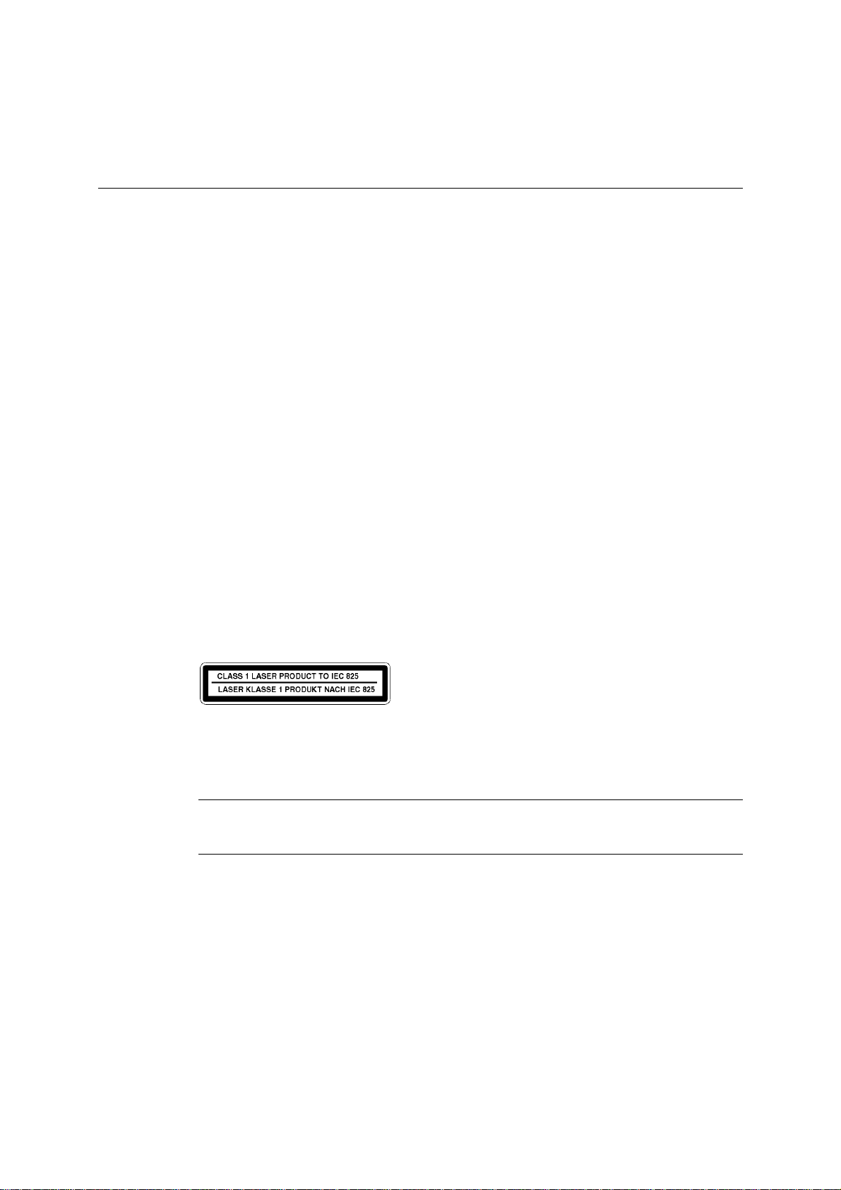
Laser products
Any CD-ROM drive fitted in this system is classified as a CLASS 1 LASER PRODUCT according to IEC825 Radiation
Safety of Laser Products (Equipment Classification: Requirements and User's Guide). The CLASS 1 LASER PRODUCT label
is located on the underside of the system unit.
The CD-ROM drive contains a laser system which is harmful to the eyes if exposed. Do not attempt to disassemble the
CD-ROM drive; if a fault occurs, call an authorised maintainer.
Use the CD-ROM drive only as described in this manual. Failure to do so may result in exposure to hazardous radiation.
Anti-static precautions
WARNING
Static electricity can cause permanent damage to electronic components. You should be aware of this risk, and take
precautions against the discharge of static electricity into the computer.
The computer is at risk from static discharge while the top cover is off. This is because the electronic components of the
motherboard are exposed. Memory modules, expansion cards and replacement processors are examples of electrostatic
sensitive devices (ESSDs).
All work that involves removing the cover must be done in an area completely free of static electricity. We recommend
using a Special Handling Area (SHA) as defined by EN 100015-1: 1992. This means that working surfaces, floor coverings
and chairs must be connected to a common earth reference point, and you should wear an earthed wrist strap and anti-static
clothing. It is also a good idea to use an ionizer or humidifier to remove static from the air.
When installing any upgrade, be sure you understand what the installation procedure involves before you start. This will
enable you to plan your work, and so minimise the amount of time that sensitive components are exposed.
Do not remove the system unit cover, nor the anti-static bag or wrapping of any upgrade, until you need to.
Handle static-sensitive items with extreme care. Hold expansion cards and add-on components only by their edges,
avoiding their electrical contacts. Never touch the components or electrical contacts on the motherboard or on expansion
cards. In general, do not handle static-sensitive items unnecessarily.
Keep all conductive material, and food and drink, away from your work area and the open computer.