Mitsubishi Electric HD-6000 User manual

CAUTION:
Before servicing this chassis, it is important that the service person read the "SAFETY PRECAUTIONS" and
"PRODUCTSAFETYNOTICE"containedinthismanual.
• Design specifications are subject to change without notice.
MITSUBISHI DIGITAL ELECTRONICS AMERICA, INC.
9351JeronimoRoad,Irvine,CA 92618-1904
Copyright © 2005 Mitsubishi Digital ElectronicsAmerica, Inc.
AllRights Reserved
MITSUBISHIELECTRIC
SerSer
SerSer
Servicevice
vicevice
vice
ManualManual
ManualManual
Manual
20052005
20052005
2005
SET TOP BOX
V26S CHASSIS
SPECIFICATIONS
• Power Input : AC 120V, 60Hz
•Power Usage : 82W
• Frequency Range : VHF 54 ~ 470MHz
UHF 470 ~ 806MHz
Analog Cable - 1 ~ 125
Digital Cable - 1 ~ 135
•Antenna Input : 2 RF 75Ω unbalanced
• Tuning : 1NTSC/ATSC/QAM
1 CableCARD™ Slot
1 NTSC for PIP
• Cabinet Dimensions : 17"(W) x 3.4"(H) x 16.8"(D)
• Weight : 27 lbs
• PVR : 120 GB Hard Disc
Approx. 12 hrs HD Recording
72 hrs SD Recording
• Analog Input : VIDEOIN JACK (RCAType)
Levels 1.0Vp-p 75Ω unbalanced
: AUDIOINJACK (RCAType)
-4.7dBm 43kΩunbalanced
: S-VIDEOINJACK
(Y/C separate type)
Y:1.0 Vp-p C:0.286Vp-p(BURST)
75Ω unbalanced
: COMP/Y, Cr,Cb (RCAType)
Y: 1.0 Vp-p Cr, Cb: 700mVp-p
: ATV/Y(G),Pr(R),Pb(B),H, V
Y: 1.0Vp-p with sync 75Ω (BNC)
Pr, Pb: 700mV 75Ω
H, V: 3.0Vp-p 75Ω
:VGA/R,G,B,V,H(15 pin D)
• Output Level : VIDEOOUTJACK (RCAType)
1.0Vp-p 75Ω unbalanced
: COMP/Y,Cr,Cb
Y: 1.0 Vp-p Cr, Cb: 700mVp-p
: AUDIOOUT JACK (RCAType)
-4.7dBm 4.7kΩ unbalanced
• Digital : IEEE-1394 I/O Jacks
Interface : AC-3 Digtal Audio Output
: HDMI™ Input/Output
: MonitorLinkTM Control/RS-232C
: CableCARD™ Slot
: NetCommand®
.
MODEL
HD-6000


MODEL: HD-6000
Page 3
INTRODUCTION ................................................................................................................................5
PRODUCTSAFETYNOTICE ............................................................................................................. 5
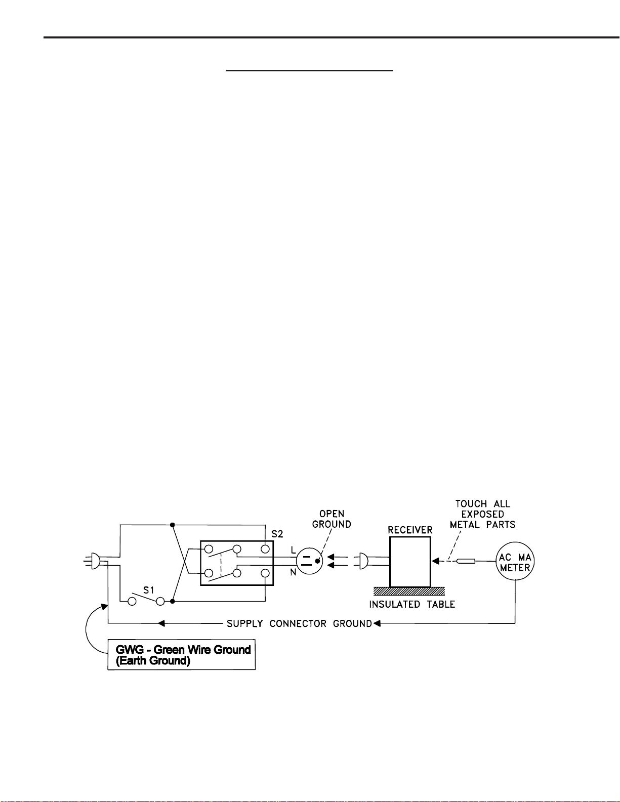
SAFETYPRECAUTIONS ...................................................................................................................6
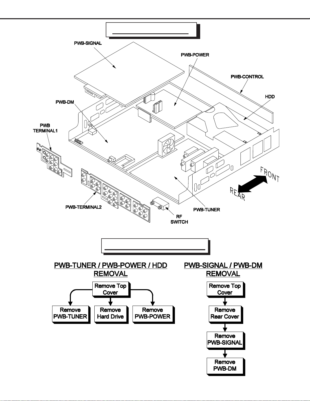
PWB-LOCATIONS .............................................................................................................................7
DISASSEMBLY ..................................................................................................................................7
DisassemblyProcedures Sequence ...................................................................................... 7
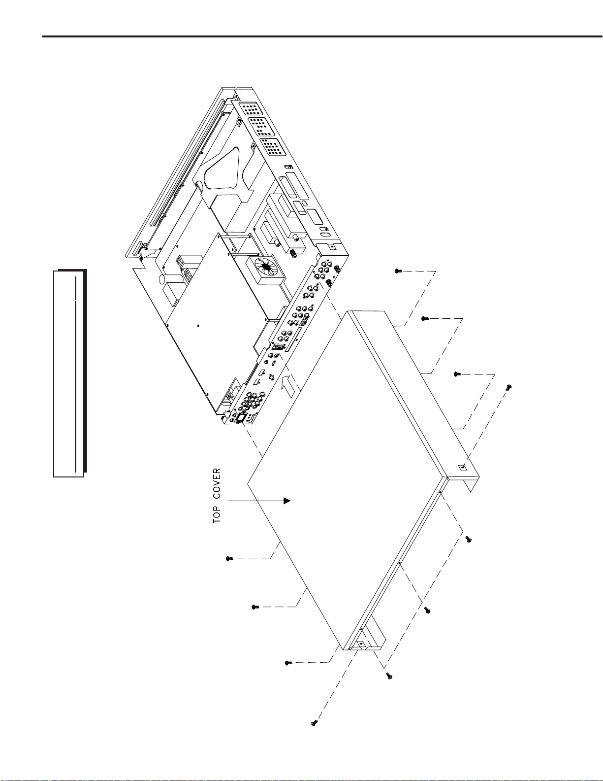
TopCoverremoval ..................................................................................................................8
HDD(HardDrive)removal .......................................................................................................9
PWB’Sremoval ................................................................................................................... 10
ELECTRICALADJUSTMENTS ........................................................................................................ 11
Equipment .................................................................................................................................... 11
Option Menu / Initialization Defaults /AV Defaults ......................................................................... 12
LED Diagnostics ........................................................................................................................... 13
RemoteControl OperationalMode ................................................................................................ 13
CircuitAdjustment Mode ............................................................................................................... 14
Transferingdata ............................................................................................................................ 15
Adjustment Items List................................................................................................................... 15
AdjustmentProcedures ................................................................................................................ 16
Test Points .......................................................................................................................... 16
Main-YGain......................................................................................................................... 16
Sub-YGain .......................................................................................................................... 17
SubPictureOffset ............................................................................................................... 17
CHIPPARTS REPLACEMENT ......................................................................................................... 18
REPLACEMENTPARTS .................................................................................................................. 19
PartsOrdering .............................................................................................................................. 19
CriticalandWarranty Parts Designation........................................................................................ 19
PartsTolerance Codes.................................................................................................................. 19
SERVICE PARTS LIST .................................................................................................................... 20
CIRCUITRYBLOCK DIAGRAMS ..................................................................................................... 29
StandbyPowerSupplies ............................................................................................................... 29
PWB-DM PowerSupplies ............................................................................................................. 30
PWB-SIGNALSwitchedPowerSupplies ...................................................................................... 30
Video Select Circuitry ................................................................................................................... 31
VideoOutputCircuitry................................................................................................................... 32
Sync Signal Selection................................................................................................................... 33
Sync Signal Output Path .............................................................................................................. 34
RecordSignalPath....................................................................................................................... 34
SoundSignalPath ........................................................................................................................ 35
Control Circuitry ............................................................................................................................ 36
CommandInput Circuitry............................................................................................................... 37
MacrovisionDetection ................................................................................................................... 37
PWB-DM Signal Path ................................................................................................................... 38
CONTENTS

Page 4
MODEL: HD-6000
Part 2
Schematic Diagrams
CONTENTS Page
SCHEMATICDIAGRAMS
OverallPWB Interconnect Diagram .................................................................................................1
POWER / E2P / CONTROL / MV Decoder] ....................................................................................2
TERMINAL-1/ TERMINAL-2 [Inputs / Outputs] ...............................................................................3
SIGNAL-1[VideoSwitch]................................................................................................................4
SIGNAL-2[Decoder/Switch]..........................................................................................................5
SIGNALS-3[Micro} .........................................................................................................................6
SIGNAL-4[TVGO] ..........................................................................................................................7
SIGNAL-5[MPEGEncoder]............................................................................................................8
SIGNAL-6[HDMIRX] ...................................................................................................................... 9
SIGNAL-7[HDMITX]..................................................................................................................... 10
SIGNAL-8[Video Output]............................................................................................................. 11
SIGNAL-9[IR232] ......................................................................................................................... 12
TUNER-1[ATSC/NTSCTuner] .................................................................................................... 13
TUNER-2[MainATSC/ NTSC Demodulators] ............................................................................... 14
PWB LAYOUT DIAGRAMS .............................................................................................................. 15

MODELS: HD-6000
Page 5
INTRODUCTION
Thisservice manual providesservice instructions for STBmodel HD-6000which usesthe V26Schassis. Service
personnelshould read this manualthoroughly before servicingthese chassis.
Thisservice manual includes:
1. SafetyPrecautions
2. Assembly and disassembly instructions.
3. Servicingprinted circuit boards (PCBs).
4. Electrical adjustments.
5. Chipparts replacement procedures.
6. Circuitpathdiagrams.
The parts list section of this service manual includes:
1. Cabinetand screen parts.
2. Electrical parts.
Schematicand block diagramsof theabove listedmodels areincluded inthis servicemanual forbetter understanding
of the circuitry. PCB drawings are also included for easy location of parts and test points.
PRODUCT SAFETY NOTICE
Manyelectrical and mechanicalparts intelevision receivershave specialsafety relatedcharacteristics. These charac-
teristics are often not evident from visual inspection nor can the protection afforded by them necessarily be obtained by
usingreplacement components rated for highervoltage, wattage, etc.
Replacementparts which havespecial safetycharacteristics areidentified inthis servicemanual.
Electrical components having such features are identified by shading on the schematic diagrams and by bold type in
the parts list of this service manual. and by marking on the supplementary sheet for this chassis to be issued subse-
quently. The replacement for any safety part should be identical in value and characteristics.

Page 6
MODELS: HD-6000
SAFETY PRECAUTIONS
NOTICE: Observe all cautions and safety related notes located inside the receiver cabinet and on the
receiverchassis.
WARNING:
1. Operationof this receiver outside thecabinet or with the coverremoved presents a shock hazard
fromthe receiver's power supplies. Workon the receivershould notbe attempted byanyone whois
notthoroughlyfamiliarwiththeprecautions necessary when working on high voltage equipment.
2. Whenservice is required, observethe original lead dress.Extra precaution shouldbe taken to
assure correct lead dress in the high voltage area. Where a short-circuit has occurred, replace those
componentsthat indicate evidence of overheating.
Leakage current check
Before returning the receiver to the customer, it is recommended that leakage current be measured according to the
followingmethods.
1. Cold Check
With the alternating current (AC) plug removed from the AC source, place a jumper across the two AC plug
prongs. Connect one lead of an ohm meter to the AC plug and touch the other lead to each exposed metal part
(i.e. antennas, handle bracket, metal cabinet, screw heads, metal overlay, control shafts, etc.), particularly any
exposed metal part that has a return path to the chassis. The resistance of the exposed metal parts having a
return path to the chassis should be a minimum of 1Mega Ohm. Any resistance below this value indicates an
abnormalcondition and requires corrective action.
2. Hot Check ...Use the circuit shown below to perform the hot check test.
1. Keep switch S1 open and connect the receiver to the measuring circuit. Immediately after
connection,andwith the switching devices ofthe receiver in theiroperating positions, measure
the leakage current for both positions of switch S2.
2. Close switch S1, energizing the receiver. Immediately after closing switch S1, and with the
switchingdevicesofthe receiver in their operating positions, measurethe leakage current for both
positions of switch S2. Repeat the current measurements of items 1 and 2 after the receiver has
reached thermal stabilization. The leakage current must not exceed 0.5 milliampere (mA).

MODELS: HD-6000
Page 7
PWB LOCATIONS
Disassembly Sequence

Page 8
MODELS: HD-6000
TOP COVER REMOVAL

MODELS: HD-6000
Page 9
HDD (Hard Drive) Removal
NOTE: Prior to HDD replacement, perform the prodedure
“Replacing the HDD” described on page 15.

Page 10
MODELS: HD-6000
PWB Removal

MODEL: HD-6000
Page 11
ELECTRICAL ADJUSTMENTS
Note: Performonlytheadjustmentsrequired.
Donotattempt an alignment if proper equipmentis not available.
Test Equipment
• Oscilloscope(Unlessotherwise specified, use 10:1 probes)
• SignalGenerator (both SD and HD capable)
Test Signal
A. Color Bar Signal
Use the color bar signal shown below, unless otherwise specified in this manual.

Page 12
MODEL: HD-6000
Defaults After Initialization
Language :English Background :Gray A/V Memory Reset :Ant-1
Color Balance -- Digital Captions :On if Mute Audio
TV Pause :On Request Appearance :Default Bass :50%
Side Bar Color :Gray Digital Settings Treble :50%
Font :Font 3 Balance :50%
Edit -- Size :Large Surround :Off
Transport Menu :On Color :White Sub Woofer :On
Default PVR -- Background :Black Listen To (Analog Only) :Stereo
Icon Order -- Opacity :Translucent Level Sound :On
Analog Quality :High Background Opacity :Translucent Language (Digital Only) :English
Video
Antenna :1 V-Chiip :Off Contrast :50%
Memorize -- TV Rating :TV-PG Brightness :50%
Prefer Digital -- FV-Fantasy Violence :Enable Sharpness :50%
Channel :3 D-Sexual Dialog :Enable Color :50%
Memory :Deleted L-Adult Language :Enable Tint :50%
Name -- S-Sexual Situations :Enable Video noise :Standard
SQV -- V-Violence :Enable Film Mode (Auto) :On
Programs Not Rated :Enable Video Mute :On
Clock Setting :Manual Movie Rating :PG Fix/Variable :Variable
Time :12:00AM V-Chip Time Scan Rate Setting :Automatic
Date :1/01/00 Start :12:00pm TV Volume :30%
Time Zone :Eastern Stop :12:00pm PIP Source :Ant-1 003
Daylight Savings Time :Applies Lock by Time PIP Position :Lower Right
Timer -- Lock by Time :Off POP Position :Right Half
Lock Time :12:00pm PIP/POP Format :Double Window
Analog Captions :On if Mute Unlock Time :12:00pm Format :Stretch
Captions Menu
V-Chip Lock Menu
Audio / VideoCaptions Menu (continued)Setup Menu
NetCommand Menu
Antenna Menu
Time Menu
DEFAULTS
A/V Reset Defaults
A/V Function Ant 1/2 Input 1/2 Component
1/2/DTV VGA HDMI 1394
Contrast Center Center Center Center Center Center
Brightness Center Center Center Center Center Center
Sharpness Center Center Center N/A Center Center
Color Center Center Center Center Center Center
Tint Center Center Center Center Center Center
V
ideo noise Standard Standard Standard N/A Standard N/A
Film Mode (Auto) On On On N/A On N/A
Bass Center Center Center Center Center Center
Treble Center Center Center Center Center Center
Balance Center Center Center Center Center Center
Surround Off Off Off Off Off Off
Listen To Stereo N/A N/A N/A N/A N/A
Level Sound On On On On On On
NOTE: Front Panel A/V Reset, resets all A/V Memory settings.
User Menu A/V Reset, resets only the selected input A/V settings.
OPTION MENU
1. Press the “MENU” button on the remote hand unit.
2. Press the buttons “2”, “4”, “7” and “0” in order.
(The screen will change to the option menu.)

MODEL: HD-6000
Page 13
A. A/V Memory
Each of the external inputs has its ownAudio/Video Memory. Achange in anA/V setting at a specific input is
stored in memory for that specific input.
B. A/V Reset
1. Press the GUIDE and FORMAT buttons on the front panel to reset allA/V Memories to default.
2. The AV Reset in the user’s menu initializes only the selected input’s A/V Memory.
LED Indicator Diagnostics
The“POWER/TIMER”LED provides an indication of thesets operation, and thepossible cause of a malfunction.
1. Initial Control Circuitry Check
Immediately after theTV is connected to anAC power source:
2. Error Code Operational Check
Note: TheSetTop Box must bein “Shut Down”and not havebeen switched Off,toperform the Error Code
Operational Check. When the unit is switched Off, the code automatically resets to “12” No Error.
Pressing the front panel “DEVICE” and “MENU” buttons at the same time, and holding for 5 seconds,
activates the Error Code Mode. The LED flashes denoting a two digit Error Code, or indicating no problem
has occured since the last Initalization.
Note: The front panel buttons must be used, NOT those on the Remote Control.
•Thenumber of flashes indicates the valueof the MSD(tens digit) of theError Code.
•Theflashingthenpauses for approximately 1/2 second.
•TheLEDthen flashes indicating the valueof the LSD (onesdigit) of theError Code.
•The Error Code is repeated a total of 5 times.
Example: If the Error Code is “35”, the LED will flash three times, pause, and then flash five times.
4. Error Codes
TheError Code designations indicatingmalfunction, orno malfunction,are listed below:
Remote Control Operational Modes
Thereare two Remote HandUnit OperationalModes, “Standard”and“NetCommandTM”. The Remote is initially
inthe “Standard”mode. The “NetCommandT”mode is usedwhen controlling HomeTheaterdevicesusing
NetCommand. Tochange the Remote Operational Mode:
•Set the Remote to the CABLE/DBS/DTV Layer.
•Point the Remote away from the STB.
•Tochange to “Netcommand” ... Hold the“Power” button and press“1-9-7” in sequence.
•Tochangeto “Standard”... Hold the“Power” button and press “0-0-0”in sequence.
LED Indications Conditions Probable Cause
Off After AC is applied Standby Power Supply or TV µPC not running
Fast Bllink for 70 sec. After AC is applied Normal DM µPC is booting up
Fast Blink (doesn't stop) After AC is applied DM µPC failed to boot up
Slow Blink Set in Off Normal - Timer is set for Automatic Turn ON
Error Code Probable Cause
12 Normal Operation - No Error Detected
35 Fan Stopped
41 Short Detected

Page 14
MODEL: HD-6000
3.Adjustment Selection
Use the “VIDEO” button to select a specific elecrtrical ajustment.
4.Adjusting Data
After selecting an adjustment item, use the “UP” and “DN” buttons to change adjustment data.
ª If the “UP” button is pressed, the adjustment data increases.
ª If the “DN” button is pressed, the adjustment data decreases.
5. Saving data
Press “ENTER” to save the adjustment data in memory.
The display characters go red for approx. one second in this step.
Note: If the circuit adjustment mode is terminated without pressing
“ENTER”,changes in adjustment data are notsaved.
6. Terminating the circuit adjustment mode
Press the “MENU” button on the remote hand unit twice to terminate the adjustment mode.
Note: Theadjustment mode canbe also terminatedby turningthe
poweroff.
CIRCUIT ADJUSTMENTS
ElectricalAdjustments
ElectricalAdjusmentsare performed inServiceAdjustmentMode.
1.Activating the adjustment mode
1. Press the “MENU” button on a remote hand unit.
(The “MENU” display will appear.)
2. Press the buttons “2”, “4”, “5” and “7” in that order. (The screen will change to the adjustment mode.)
If not changed to the adjustment mode, repeat steps 1 and 2.
2.Adjustment Function Selection
Use the “AUDIO” button to select a specificAdjustment Function.
AD9883A
SMTX MMTX
Functions

MODEL: HD-6000
Page 15
SERVICE MODE - Adjustment Items and Initial Data Values
MAIN MATRIX
Item # Abbrev. Description Data Range Initial Data
1 TNTM Main Tint adjustment 0~63 28
4 COLM Main Color adjustment 0~63 20
14 YDRM Main Y gain control 0~31 5
18 UPDM Main Pb Pedestal adjustment 0~15 7
19 VPDM Main Pr Pedestal adjustment 0~15 7
SUB MATRIX
Item # Abbrev. Description Data Range Initial Data
1 TNTS Sub Tint adjustment 0~63 28
4 COLS Sub Color adjustment 0~63 18
14 YDRS Sub Y gain control 0~31 5
18 UPDS Sub Pb Pedestal adjustment 0~15 7
19 VPDS Sub Pr Pedestal adjustment 0~15 7
AD9883
A
Item # Abbrev. Description Data Range Initial Data
12 ROFF Red Offset 0~27 55
14 BOFF Blue Offset 0~27 59
Replacing the HDD
Priorto replacing the HDDAssembly, perform the following steps.
1) Disconnectall external IEEE1394 devices.
2) Enterthe Option Menu ...Press “MENU-2-4-7-0”
3) Select TV Disc. Press “Enter.” Wait for confirmation and press “Enter” again.
Transferring Data
1) Enterthe ServiceAdjustmentMode ... Press “MENU-2-4-5-7”
2) Press “0” when in the Service Mode ... Three choices appear at the top of the screen.
3) User UP & DN keys to highlight the desired choice, the Press “ENTER”
Display Description
Backup DVC files to CF Copies Alignment data to compact flash
Restore DVC files from CF Loads Alignment data from compact flash
Copy WB Alignment Used to transfer WB data from signal E2P to DM E2P
Data Transfer Definitions

MODEL: HD-6000
Page 16
Purpose:
Measuring
Instrument
Test Point
Measuring
Range
Input Signal
Ext. Trigger
Input Terminal
Symptom:
Purpose:
Measuring
Instrument
Test Point
Measuring
Range
Input Signal
Ext. Trigger
Input Terminal
Symptom:
[Video Circuit]
1. Main-Y Gain
To set the main picture Ylevel
Incorrectanalogsourcemainpicturebrightnesslevel.
Oscilloscope
TPY
------
-------
Color bars
External Input
1. Supply a Color Bar pattern with 100% white signal to an External Input. Select
the Color Bars as the source (Device button).
2. Connect a scope to TPY (Main Luminance).
3. Enter the Alignment Mode (MENU-2-4-5-7)
4. Select the MMTX function (AUDIO button).
5. Select adjust item #14 YDRM (VIDEO button).
6. Set the data so the waveform at TPY is 0.7 Vp-p ±0.03 Vp-p (ADJUST buttons).
7. Press “ENTER” to save data.
8. Press “MENU” twice to exit the service mode.
TEST POINTS
TPSY TPY
PWB-SIGNAL (Partial)
TPSY TPY
PWB-SIGNAL (Partial)

MODEL: HD-6000
Page 17
Purpose:
Measuring
Instrument
Test Point
Measuring
Range
Input Signal
Ext. Trigger
Input Terminal
Symptom:
Purpose:
Measuring
Instrument
Test Point
Measuring
Range
Input Signal
Ext. Trigger
Input Terminal
Symptom:
[Video Circuit]
3. Sub Picture Offset
To match sub picture white to main picture white
Subpicture white differsfrom whitein themain picture.
----
----
------
-------
Full White Raster
External Input
1. Supply a full white raster signal to an External Input.
2. Select the White raster as the source for both the main and sub pictures.
3. Use the PIP/POP buttion to select the Single PIP mode.
4. Enter the Alignment Mode (MENU-2-4-5-7)
4. Select the AD9883A function (AUDIO button).
5. Select item #12 ROFF and #14 BOFF (VIDEO button).
6. Set the data fore items #12 and #14 so the sub picture white is close to that in
the main picture. (ADJUST buttons).
7. Press “ENTER” to save data.
8. Press “MENU” twice to exit the service mode.
[Video Circuit]
2. Sub-Y Gain
To set the sub picture Ylevel
Incorrectanalogsourcesubpicturebrightnesslevel.
Oscilloscope
TPY& TPSY
------
-------
Color bars
External Input
1. Supply a Color Bar pattern with 100% white signal to an External Input.
2. Select the Color Bars as the source for both the main and sub pictures.
2. Connect a scope to TPY (Main Luminance) & TPSY (Sub Luminance).
3. Enter the Alignment Mode (MENU-2-4-5-7)
4. Select the SMTX function (AUDIO button).
5. Select adjust item #14 YDRS (VIDEO button).
6. Set the data so the waveform at TPSY equals TPY. (ADJUST buttons).
7. Press “ENTER” to save data.
8. Press “MENU” twice to exit the service mode.
TPSY TPY
PWB-SIGNAL (Partial)

PAGE18
MODEL: HD-6000
CHIP PARTS REPLACEMENT
Some resistors, shorting jumpers (0 Ohm resistors),
ceramic capacitors, transistors and diodes are chip parts.
Thefollowing precautions should be taken when replacing
these parts.
Cautions:
1. Usea fine tipped, wellinsulated soldering iron
(approximately30watts), and tweezers.
2. Meltthe solder andremove thechip parts
carefully so as not to tear the copper foil from
theprintedcircuit board.
3. Discardremoved chips; do notreuse them.
4. Donot apply heat formore than 3(three)
seconds to new chip parts.
5. Avoidusing a rubbing stroke when soldering.
6. Take care not to scratch, or damage the chip
partswhen soldering.
7. Supplementarycementing is not required.
Chip Parts Removal (Resistors, Capacitors, etc.)
1. Grasp the part with tweezers. Melt the solder
atboth sides alternately, and remove oneside
of the part with a twisting motion.
2. Melt the solder at the other side and remove
thepart.
Chip Parts Removal (Transistors)
1. Melt the solder of one lead and lift the side of
thatlead upward.
2. Simultaneously melt the solder of the other
two leads and lift the part from the PCB.
Replacement
1. Presolder the contact points on the circuit
pattern.
2. Pressthe part downward with tweezers and
applythe soldering ironas shown.

PAGE19
MODEL: HD-6000
Parts Ordering
To expedite deliveryof replacement partsorders, specifythe following:
1. ModelNumber/SerialNumber
2. PartNumber and description
3. Quantity
Note: Unless complete information is supplied, delay in processing of orders will result.
Critical and Warranty Parts Designation
Critical Electrical Components are indicated by Bold Type in the Parts List, and in the schematic
diagramsbyshading.
Warranty Return Parts are indicated in the Parts List with an (*).
Parts Tolerance Codes
Refertothe following chart for tolerancecharacteristics of electrical components.
MARK B C D F G J K
Tolerance % ± 0.1 ± 0.25 ± 0.5 ± 1 ± 2 ± 5 ± 10
MARK M N V X Z P Q
Tolerance % ± 20 ± 30 ± 10 + 40 + 80 + 100 + 30
-20 -20 - 0 -10
MARK M N V X Z
Tolerance (pF) ± 0.1 ± 0.25 ± 0.5 ± 1 ± 2
REPLACEMENT PARTS

Ref # Part # Part Name & Description [#]
PAGE20
Ref # Part # Part Name & Description [#]
MODELS: HD-6000
INTEGRATEDCIRCUITS
IC2000 276P090010 IC-C-MOS- SiI9993
IC2010 261P829010 TR-CHIP - NDC7002N
IC2020 275P981010 IC-C-MOS-24LCS22AT/SN
IC2040 271P071010 IC - BA033SFP
IC2050 261P829010 TR-CHIP - NDC7002N
IC2C00 275P989010 IC-C-MOS-MAX3223ECAP
IC2C01 276P020010 IC-C-MOS-SN74LVC2G14DBVR
IC2C02 276P064010 IC-C-MOS-SN74LVC1G125DBV
IC2C03 276P064010 IC-C-MOS-SN74LVC1G125DBV
IC2K01 271P061010 IC - CXA2189Q
IC2L00 271P078010 IC - MM1566AJBE
IC2L70 270P938010 IC - MC33202D
IC2M01 275P947010 IC-C-MOS-UPD64083
IC2M02 272P379020 IC - LM1881MX (NSC)
IC3B01 270P938010 IC - MC33202D
IC3C01 276P146010 IC-C-MOS - CS5340-CZR
IC3E01 276P147010 IC-C-MOS-CS8405A-CZR
IC3E02 276P064010 IC-C-MOS-SN74LVC1G125DBV
IC3E03 275P356010 IC-C-MOS - TC74VHCU04FT
IC3J01 271P060010 IC - CXA2188Q
IC54Z1 275P657050 IC-C-MOS - 24LC256T-I/SN
IC54Z3 276P174010 IC-C-MOS-AT24C512N-10S1-2.7
IC54Z4 270P880010 IC - 24LC64I/SN
IC5A01 276P114010 IC-C-MOS - SiI 9190
IC5A03 261P829010 TR-CHIP - NDC7002N
IC5G01 271P071010 IC - BA033SFP
IC5H01 270P998010 IC-C-MOS- LM317EMP
IC5J01 275P778010 IC-C-MOS-AD7196AKS
IC5J10 279P069030 IC - SN74LVTH244APW
IC5J20 276P187010 IC-C-MOS - ICS574MIT
IC5P01 276P148010 IC-C-MOS-ispMACH -4128V-5T100C
IC5T01 270P997010 IC-C-MOS-SM5301AS
IC5U01 271P099010 IC - LD29150PT50R
IC7A00 276P017010 IC-C-MOS - M306V7FGFP
IC7A01 275P533010 IC-C-MOS - M24C64WM6T
IC7A02 270P706020 IC - MAX823REUK
IC7A03 270P575020 IC - NJM78M05DLA - TEI
IC7A04 275P718010 IC-C-MOS - TC74HC4053FT
IC7D00 275P278010 IC-C-MOS- TC74LVX14FT
IC7D01 270P818020 IC - CXA3506R
IC7DA1 267P176010 HIC - AF-9412
IC7DB0 270P677010 IC - BA033FP
IC7DC0 270P992010 IC - BA18BC0FP
IC7E01 275P894010 IC-C-MOS-AD9883AKST-110
IC7E02 275P663030 IC-C-MOS-M4A3-32/32-5VC-48
IC7H00 276P106010 IC-C-MOS-MB87M1823PFV-ES-BND
IC7K21 270P831010 IC-C-MOS-OPA2350PA
IC7M00 276P091010 IC-C-MOS-M12L64322A-6T
IC7N01 275P682010 IC-C-MOS-TC74VCX16244FT
IC7N02 275P682010 IC-C-MOS-TC74VCX16244FT
IC7P01 275P943030 IC-C-MOS-PIC18F252T-I/SO030
IC7P03 263P154010 IC-C-MOS-SN74HC132DB
IC7P04 271P023010 IC - SN74CBTD1G125DBVR
IC7P30 275P718010 IC-C-MOS - TC74HC4053FT
IC7P31 271P023010 IC - SN74CBTD1G125DBVR
IC8001 276P030030 IC-C-MOS-215H31AGA12H
IC8002 270P706020 IC - MAX823REUK
IC8003 276P064010 IC-C-MOS-SN74LVC1G125DBV
IC8004 276P064010 IC-C-MOS-SN74LVC1G125DBV
IC8101 271P033010 IC - LP2996MRX
IC8102 276P201010 IC-C-MOS-K4H561638F-TCCC
IC8103 276P201010 IC-C-MOS-K4H561638F-TCCC
IC8104 276P201010 IC-C-MOS-K4H561638F-TCCC
IC8105 276P201010 IC-C-MOS-K4H561638F-TCCC
IC81A1 270P991010 IC - IRU3037CS
IC81A2 261P135010 FET-HEX - IRF7313
IC81A3 270P879030 IC - SC1566I5M-2.5TR
IC81A4 270P992010 IC - BA18BC0FP
IC81A5 270P879030 IC - SC1566I5M-2.5TR
IC81A6 270P037020 IC - MIC29301-5.0BU
IC81A7 270P999010 IC - NJM2370R09
IC8205 276P042010 IC-C-MOS- MIC2544-1BM
IC8211 276P201010 IC-C-MOS-K4H561638F-TCCC
IC8212 276P201010 IC-C-MOS-K4H561638F-TCCC
IC8280 275P955010 IC-C-MOS - RTC-8564JE
IC8301 275P677010 IC-C-MOS-SN74LVC573APWR
IC8302 275P677010 IC-C-MOS-SN74LVC573APWR
IC8303 275P677010 IC-C-MOS-SN74LVC573APWR
IC8305 275P956020 IC-C-MOS-MD2811-D32-V3
IC8307 275P983010 IC-C-MOS-XR16L2750CM
IC8308 276P077010 IC-C-MOS - ST013T
IC8309 275P660020 IC-C-MOS-CS4341-KSR
IC8310 275P270010 IC-C-MOS-M66010GP
IC8311 275P769010 IC-C-MOS - TC74AC157FT
IC8313 276P145010 IC-C-MOS-MSP4440G QI-C13
IC8314 275P677010 IC-C-MOS-SN74LVC573APWR
IC8315 275P464010 IC-C-MOS - TC7WH14FK
IC8316 276P064010 IC-C-MOS-SN74LVC1G125DBV
IC8317 275P786010 IC-C-MOS - TC7SA08FU
IC8401 275P624010 IC-C-MOS-TSB42AA4
IC8402 275P686010 IC-C-MOS-TSB41AB3PFP
IC8501 275P679010 IC-C-MOS - TC74LCX74FT
IC8502 275P124040 IC-C-MOS-SN74LVC245APWR
IC8503 275P677010 IC-C-MOS-SN74LVC573APWR
IC8504 271P036020 IC - TPS2221PWPR
IC8505 275P677010 IC-C-MOS-SN74LVC573APWR
IC8506 276P065020 IC-C-MOS-CIMAX(103563)
IC8507 275P680010 IC-C-MOS - TC74VCX257FT
IC8508 275P675010 IC-C-MOS-SN74LV125APWR
IC8509 271P036020 IC - TPS2221PWPR
IC8600 275P983010 IC-C-MOS-XR16L2750CM
IC8601 275P122020 IC-C-MOS-SN74LV32APWR
IC8602 275P676010 IC-C-MOS-SN74LVC139APWR
IC8705 275P769010 IC-C-MOS - TC74AC157FT
IC8706 276P145010 IC-C-MOS-MSP4440G QI-C13
IC8707 276P089010 IC-C-MOS - TC7W66FU
IC8708 271P072030 IC - LD29150DT50
IC8709 271P082010 IC - LD1117DT12
IC8710 271P072010 IC - LD29150DT25
IC8711 295P527010 TUNER-NTSC DEMODULATOR
IC8712 276P109010 IC-C-MOS-CS4334-KS
IC8713 270P938010 IC - MC33202D
IC8719 271P023010 IC - SN74CBTD1G125DBVR
IC8720 271P023010 IC - SN74CBTD1G125DBVR
IC8721 270P677030 IC - BAO9FP
IC8722 271P064010 IC - TA75S01F
IC8723 271P072020 IC - LD29150DT33
Other manuals for HD-6000
1
Table of contents