Mitsubishi Electric DX-TL5000EZ User manual

1
ENGLISHDEUTSCHFRANÇAISESPAÑOLITALIANONEDERLANDS
OTHERS
DIGITAL RECORDER
USER’S MANUAL
MODEL
DX-TL5000E400
DX-TL5000E(Z)
THIS INSTRUCTION MANUAL IS IMPORTANT TO YOU. PLEASE READ IT BEFORE USING YOUR DIGITAL RECORDER.

•••••••••••••••••••••••••••••••••••••••••••••••••••••••••••••••••••••••••••••••••••••••••••••••••••••••••••••••••••••••••••••••••••••••••••••••••••••••••••••••••••••••••••••••••••••••••••••
2
HEAVY OBJECTS SHOULD NEVER BE PLACED ON THE UNIT (E.G., MONITOR)
This unit complies with the requirements of the EC Directive 2004/108/EC, “EMC Directive” and 2006/95/EC, “Low Voltage
Directive”. The requirements for the susceptibility according to EN 55024 and the requirements for interference according
to EN 55022 are observed for the operation on residential areas, business, light industrial premises and in small scale
enterprises, inside as well as outside of the building. All places of operation are characterised by their connection to the
public low voltage power supply system. This unit is manufactured in accordance with EN 60950-1.
MAINS LEAD CONNECTION
The mains lead on this unit is fitted with a non-rewireable mains plug, incorporating a 5A fuse. If you need to replace the
fuse, use a 5A fuse approved by BSI or ASTA to BS 1362, ensuring you refit the fuse cover. If the mains plug is not suitable
for the sockets in your home, and you require to remove the plug, remove the fuse, cut off the plug then dispose of the plug
immediately, to avoid a possible electric shock hazard. To refit a new plug, follow these instructions; Green-and-yellow:
Earth, Blue: Neutral and Brown: Live. As the colours in the mains lead of this unit may not correspond with the coloured
markings identifying the terminals in your plug, proceed as follows.
• The wire which is coloured green-and-yellow must be connected to the terminal in the plug which is marked by the letter
E or by the safety earth symbol or coloured green or green-and-yellow.
• The wire which is coloured blue must be connected to the terminal which is marked with the letter N or coloured black.
• The wire which is coloured brown must be connected to the terminal which is marked with the letter L or coloured red.
NEVER TOUCH OR INSERT ANY OBJECT INSIDE THE UNIT
Touching the inside of the cabinet or inserting foreign objects of any kind through the disc loading slot or ventilation holes not
only creates a safety hazard but can also cause extensive damage.
PROTECT THE POWER CORD
Damage to the power cord may cause fire or shock hazard. If the power cord is damaged, turn OFF the MAIN switch and
carefully unplug the cord by holding the main plug.
If this unit is moved with the power on status, the built-in HDD may be damaged. Confirm that more than one minute have
passed since the power cord and the connecting cords were disconnected, then move this unit. Make sure to take the disc out
and close the disc loading slot.
UNPLUG THE POWER CORD DURING A LONG ABSENCE
Turn off the power and unplug the power cord during a long absence.
MAINTAIN GOOD VENTILATION
Do not obstruct the many ventilation holes on the unit. For maximum ventilation, leave some space around the unit and place
the unit on a hard level surface only, and ensure it is not covered during use. Heavy objects should never be placed on the unit.
WHEN NOT IN USE
When not in use, always eject the disc and turn OFF the MAIN switch.
CABINET CARE
Never use petroleum-based cleaners. Clean with a soft cloth moistened with soap and water and wipe dry.
PVC cables or leads should not be left in contact with the cabinet surface for long periods.
INSTALLATION LOCATION
For excellent performance and lasting reliability install in a location that is:-
1. Well ventilated, out of direct sunlight and away from direct heat.
2. A solid vibration-free surface.
3. Free from high humidity, excessive dust and away from magnetic fields.
4. Please ensure that the ventilation fan located on the unit’s back panel is not blocked.
UNSUITABLE LOCATIONS
Placing the unit in the following places might shorten the product life:
• Extremely cold places, such as refrigerated warehouses and ice houses
• Places where excessive hydrogen sulfide is likely to be generated, such as hot-springs areas
• Places or locations with salt air environment.
THIS EQUIPMENT DOES NOT PROVIDE CONNECTION FOR USED WITH OUTDOOR OR CABLE DISTRIBUTION
SYSTEMS.
NO OBJECTS FILLED WITH LIQUIDS, SUCH AS VASES, SHALL BE PLACED ON THE APPARATUS.
DO NOT PLACE HEAVY OBJECT ON THIS UNIT.
DO NOT STEP ONTO THIS UNIT.
DO NOT PLACE ANY OBJECTS IN FRONT OF THE DISC LOADING SLOT.
The unit may drop or fall by losing its balance. It may cause injury or failure of the unit.
WARNING: TO PREVENT FIRE OR SHOCK HAZARD, DO NOT EXPOSE THIS APPARATUS TO RAIN OR MOISTURE.
THIS APPARATUS MUST BE GROUNDED.
Caution and care

ENGLISH
•••••••••••••••••••••••••••••••••••••••••••••••••••••••••••••••••••••••••••••••••••••••••••••••••••••••••••••••••••••••••••••••••••••••••••••••••••••••••••••••••••••••••••••••• Beginning
3
• This unit uses a built-in HDD, which is a precision device. Please handle this unit with sufficient care.
• Do not subject this unit to vibrations or shocks. This may cause trouble specially when the power of the unit is turned on
or when the HDD is being accessed, and sufficient care is required.
• Do not disconnect the power plug while the power of the unit is turned on or while recording or playing.
• For early detection of faults, we recommend that you request inspection once a year.
There may be cases when the unit’s built-in motion detection function does not operate properly due to external condition or
video input signal or other factors.
The user will not be indemnified for problems (e.g., recording failure or playback failure) that occur with either the unit or a
connected device during operation. It is recommended to back up the important recordings regularly as a precaution against
possible breakdowns and accidents.
Recordable time and product warranty
Continuous recordable time and the estimated time displayed on the menu screen indicate the continuous time of recording
operation of this unit. They indicate the period neither for product warranty nor that for reliability of used parts.
Notice about construction of the surveillance system using this unit
•This unit can be controlled by the external devices via RS-232C terminal or LAN terminal. This unit can also be used to
control external devices via external terminal, RS-422/485 terminal, or RS-232C terminal. Owning to these functions, this
unit flexibly applies to the high grade security system, but the whole surveillance system may be affected by the malfunction
of this unit or the external devices depending on the setting contents of this unit, the connection with the external devices,
or combination between this unit and the external devices.
• When configuring a surveillance system using this unit, it is recommended to confirm first that this unit operates normally
with the other devices connected.
• It is recommended to copy or back up the important recorded contents.
• Damages rising out of any operational error of the surveillance system or loss of the recorded data or any other damages
because of any user malfunction of this unit are not covered.
• Do not use the notification function of this unit for making critical judgement nor any purpose related to human lives.
• When this unit cannot recognize the external device which is being used for recording due to the power failure, decreased
voltage, or other failures, the recording point may be moved to the internal HDD of this unit or the other external HDD. To
prevent occurrence of such problem, it is recommended to use uninterruptible power supply.
• If the power plug is disconnected or the breaker switch is turned off during recording, HDD may be damaged or playback
of recorded data may become impossible. If the breaker switch is turned on and off everyday, set the timer recording to be
performed only for the period that the breaker is on and do not turn off the breaker during recording.
Note: This symbol mark is for EU countries only.
This symbol mark is according to the directive 2002/96/EC Article 10 Information for users and Annex IV.
Your MITSUBISHI ELECTRIC product is designed and manufactured with high quality materials and components which can
be recycled and reused.
This symbol means that electrical and electronic equipment, at their end-of-life, should be disposed of separately from your
household waste.
Please, dispose of this equipment at your local community waste collection/recycling centre.
In the European Union there are separate collection systems for used electrical and electronic product.
Please, help us to conserve the environment we live in!
DISCLAIMER
In any event, Mitsubishi assumes no responsibility or reliability for the following:
1. Disassembly, repair, or alteration of this unit by user or installer.
2. Failure or breakdown in or damage to this unit resulting from misuse or careless handling by user or installer.
3. Inconvenience or damages arising out of inability to display or record images due to any reason or cause other than
breakdown or failure in this unit.
4. Failure in this unit due to combination with other equipment manufactured by a third party or inconvenience or damages
resulting from such failure.
5. Inconvenience, damages, or claims arising out of breakdown in this unit or loss of recorded video data due to replace-
ment of the built-in HDD by user or installer.
6. Inconvenience or damages arising out of breakdown in this unit or inability to display or record images due to natural
disaster including earthquake and storm.
7. Inconvenience, damages, or claims arising out of breakdown in this unit or loss of recorded video data due to impact or
vibration to the built-in HDD or an environmental factor such as temperature at the installation site.
8. Demand for damages or other claim of infringement of privacy if the images monitored or recorded by user become
public or are used for any purpose other than surveillance for whatever reason.
The HDD and cooling fan of this unit are driving parts. When operated in an ambient temperature of 25 °C, it is recommended
that both of these parts are replaced every 30,000 hours for stable recording.
(This interval is for reference purpose only and does not indicate the warranty period of the parts.)

•••••••••••••••••••••••••••••••••••••••••••••••••••••••••••••••••••••••••••••••••••••••••••••••••••••••••••••••••••••••••••••••••••••••••••••••••••••••••••••••••••••••••••••••••••••••••••••
4
INSTALLATION LOCATION AND HANDLING
• Place this unit horizontally and in a stable place. If this unit is not placed correctly and used in an unstable place, the unit
may be damaged such as removal of the DVD/CD disc.
• Do not place this unit close to other electronic or magnetic equipment. This will avoid video and audio distortion.
• When a monitor and this unit are placed vertically, the pictures may be distorted or DVD/CD disc may not be ejected.
• Do not let stick your hands into the disc loading slot. You may get your hand caught in the slot and may got injured. If you get
your hand caught, do not get out of the slot by force. Contact your dealer after turning off the power and disconnecting the
plug.
DVD/CD DISC
• Do not use the disc cracked, deformed or repaired with adhesive. The disc may fly into pieces and cause injury.
• Do not touch the playback surface when holding the disc.
• When dew condensation occurs on the disc, wipe the surface off before use.
• Dirt such as fingerprints or dust causes the deterioration of the picture quality and audio quality. Gently wipe the DVD/CD
disc from the centre to the outside with a soft cloth.
• When the disc is very dirty, soak a soft cloth with water and screw water of it, wipe off the dirt lightly, then wipe with a dry
cloth.
• Do not use solvent such as benzine and thinner, a record cleaner, and static-stopper. They may damage the disc.
• Do not use the disc described below. They may damage the disc itself or this unit.
Discs on which a piece of paper or sticker is put, or a disc damaged.
Discs which the label is peeled or a disc with oozing.
Discs cracked, deformed, or repaired with adhesive.
• Store the disc in the specified casing, avoiding the following places.
Places where it will be subjected to direct sunlight.
Places with excessive dust.
Places where it will be subjected to high temperatures or high humidity.
• DVD movie (cinema) or personal recorded picture cannot be played back on this unit. Only the pictures recorded on this unit
can be played back.
• Do not use the disc which has been used on the personal computer, failed to be copied, or stopped during copying due to
the power failure because they may cause malfunction of the unit.
• Although you can copy the data on DVD/CD with this unit and playback that data on the personal computer using the
supplied application software, not all the personal computers or DVD/CD drives are ensured for proper playback of such
data.
MAINTENANCE OF THE LENS FOR RECORDING/PLAYBACK (LASER PICKUP)
• When any dust adheres on the lens for recording/playback, the picture may be distorted or the audio may skip. Also normal
recording or playback may not work. Ask your dealer how to correct this problem.
Be careful, do not use the commercial lens cleaning disc, they may damage the lens.
PRECAUTION CONCERNING EXTERNAL DEVICE
• The various external HDDs can be connected to this unit in order to expand the memory or to use as the copy device.
However, during recording or playing back a picture at high rate, some pictures may be missed due to the slow rate of data
transfer or the slow speed of response from the external device connected. Be sure to check the operation sufficiently in
advance.
• Do not use the power control function of the external device which uses bus power of this unit.
• The external device to be used may be unsuitable for the operation you want to set. It is recommended to consult your
dealer when using the external device.
PRECAUTION FOR COPY USING NAS
• With this recorder, NAS* complying with NFSv3* is usable. However, proper operation is not ensured when connecting with
some NAS on the market.
The data transmission speed is about 1-2 Mbps, however, it depends on operational condition of the recorder, NAS server
performance, and network condition. It is highly recommended to check the operation sufficiently in advance before installation.
For making settings of NAS server and network, consult their respective administrators and also see the instruction manual
supplied with NAS.
Consult your dealer for the latest information about operational check of NAS.
NAS*: Network Attached Storage
NFSv3*: Network File System version 3
Caution and care (continued)
Warning
This is a class A product. In a domestic environment this product may cause radio interference in which case the user may
be required to take adequate measures.

ENGLISH
•••••••••••••••••••••••••••••••••••••••••••••••••••••••••••••••••••••••••••••••••••••••••••••••••••••••••••••••••••••••••••••••••••••••••••••••••••••••••••••••••••••••••••••••• Beginning
5
Caution and care ............................................................ 2-4
Contents............................................................................. 5
Note .................................................................................... 6
Software License Agreement ........................................... 7
How to set the menus .................................................. 8-11
Setting the menus ............................................... 8-10
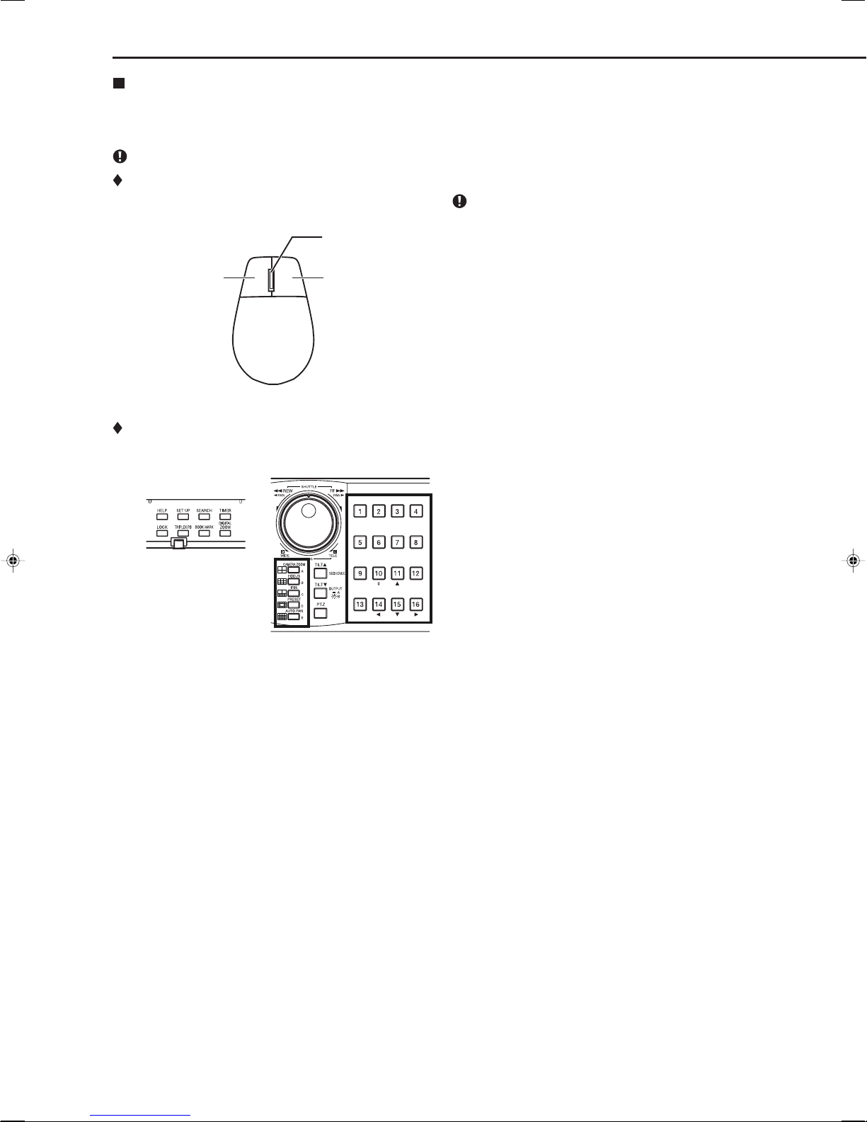
Setting the menu using a mouse ....................... 8
Setting the menu using the front panel buttons . 8
Displaying a menu screen .................................. 9
Closing a menu screen ...................................... 9
Selecting an item ............................................... 9
Inputting numbers ............................................ 10
Setting parameters ........................................... 10
Symbols in the menus ............................................ 11
Setting the time and date ............................................... 12
Time/Date Setting (Setup Menu System Time/Date
Setting) .................................................................. 12
Using the basic multiplexer functions .......................... 13
Basic multiplexer functions .................................... 13
Multiplexer buttons ........................................... 13
Using the cascade function ........................................... 14
Cascade ................................................................. 14
Controlling the camera ................................................... 15
PTZ control using the menu (User Menu PTZ
Control) .................................................................. 15
PTZ control using the front panel buttons .............. 15
Recording the picture manually .................................... 16
Basic manual recording ......................................... 16
Setting the recording rate and picture grade for
normal recording .............................................. 16
Playing back the recorded data ..................................... 17
Basic playback ....................................................... 17
Searching the desired picture .................................. 18,19
Basic search ..................................................... 18,19
Search by Time and Date ................................ 18
Search by Alarm List ........................................ 19
Copying the recorded data........................................ 20-23
Copy (User Menu Copy) ................................. 20,21
Copy Data to Copy 1 Drive/Set Copy 1 Drive .. 20
Copy Data to Copy 2 Drive/Set Copy 2 Drive
.................................................................... 20,21
Copying the data of this unit to a video cassette
............................................................................... 21
Playback software ............................................. 22,23
System requirements ....................................... 22
Starting up the application software ................. 22
Operational panel ........................................ 22,23
File menu ......................................................... 23
Search menu .................................................... 23
Operation menu ............................................... 23
Bookmark menu ............................................... 23
View menu ....................................................... 23
Grouping menu ................................................ 23
Menus apperaing with right button clicking ...... 23
• Viewing displays
(Refer to this information when operating):
Reference information concerning operation
(Caution required):
Cautionary items concerning operation
• Finding desired information
There is a “Contents” at the beginning of this manual.
• Troubleshooting
Read Troubleshooting (pages 32, 33) for possible
remedies to the problem.
How to read this manual
Microsoft is either registered trademarks or trademarks
of Microsoft Corporation in the United States and/or
other countries.
Contents
Communications by Web Browser ........................... 24-31
Communications by Web Browser ......................... 24
The personal computer product requirements . 24
Connections ..................................................... 24
Login ................................................................. 24,25
Main Menu ........................................................ 25-31
Live Monitoring ................................................. 26
Playback........................................................... 27
Configuration Menu ..................................... 28-31
User Registration ................................... 28,29
Recorder Title & Camera Titles ................... 29
E-mail Setup........................................... 29,30
NAS Setup .................................................. 30
Clock Setup ................................................. 31
Logout .............................................................. 31
Change Login User .......................................... 31
Troubleshooting ......................................................... 32,33
Warnings and CALL OUT output .............................. 34,35
Warnings and their appropriate countermeasures
.......................................................................... 34,35

•••••••••••••••••••••••••••••••••••••••••••••••••••••••••••••••••••••••••••••••••••••••••••••••••••••••••••••••••••••••••••••••••••••••••••••••••••••••••••••••••••••••••••••••••••••••••••••
6
Note
Thank you for purchasing Mitsubishi digital recorder DX-TL5000E400/DX-TL5000E(Z) (hereinafter referred to as “Product”).
Before using this Product, please be sure to read the following Software License Agreement with regard to the software
contained in this Product (hereinafter referred to as “Licensed Software”). By using this Product, you are agreeing to be
bound by the terms and conditions of the following Software License Agreement.
This Product contains software programs that are covered by GNU General Public License or GNU Lesser General Public
License. Such software programs are excluded from Licensed Software and not covered by the following Software License
Agreement. For the terms and conditions for use of the software programs covered by GNU General Public License or GNU
Lesser General Public License, please see “Notice about software to which GNU GPL/LGPL is applied”*.
In addition, this Product contains “Apache” and “OpenSSL (including “Original SSLeay” library).” These software programs
are also excluded from Licensed Software and not covered by the following Software License Agreement. For the terms and
conditions for use of these software programs, please see “Notice about Apache software”* and “Notice about OpenSSL
software”*.
Each of “Berkeley Database,” “agetty,” “expat,” and “zlib” contained in this Product is other open source software. These
software programs are excluded from Licensed Software and not covered by the following Software License Agreement. For
the terms and conditions for use of these software programs, please see “Notice about other open source software”*.
*The documents of “Notice about software to which GNU GPL/LGPL is applied,” “Notice about Apache software,” “Notice about
OpenSSL software,” and “Notice about other open source software” are contained (in the format of electronic files as
notice_GPL_LGPL_ja.pdf, notice_Apache_ja.pdf, notice_OpenSSL_ja.pdf, and notice_other_ja.pdf) in the “OpenSoft_License”
folder in the accessory CD supplied with this Product.

ENGLISH
•••••••••••••••••••••••••••••••••••••••••••••••••••••••••••••••••••••••••••••••••••••••••••••••••••••••••••••••••••••••••••••••••••••••••••••••••••••••••••••••••••••••••••••••• Beginning
7
This Software License Agreement (“Agreement”) is an agreement between you (“User”) and Mitsubishi Electric Corporation
(“Licensor”) with regard to the license to use Licensed Software.
Article 1 (Grant of license)
Licensor hereby grants to User a nonexclusive, nontransferable license to use Licensed Software.
Article 2 (License)
1. The license to use Licensed Software granted hereunder shall mean the User’s right to use Licensed Software solely
on this Product. User is hereby allowed to refer to the descriptions and instructions related to Licensed Software
contained in the user’s guide of this Product to the extent necessary for use of such Licensed Software.
2. User shall not reproduce, copy, or modify, in whole or in part, or make addition or alteration to Licensed Software and
pertinent documents.
3. User shall use Licensed Software in accordance with the operating instructions described in the user’s guide.
Article 3 (License conditions)
1. User shall not transfer to any third party the license stipulated in the preceding article.
2. User shall not disassemble, decompile, or otherwise analyze the source code of Licensed Software.
Article 4 (Ownership of Licensed Software)
All and any rights including copyrights related to Licensed Software and pertinent documents shall be owned by
Licensor or the original right holder who granted to Licensor the right to sublicense Licensed Software (hereinafter
referred to as “Original Right Holder”). User shall not own any rights other than the license granted hereunder with
regard to Licensed Software and pertinent documents.
Article 5 (Disclaimer)
Licensor and Original Right Holder shall make no warranties whatsoever with regard to Licensed Software and have
no liability for any damages suffered by User or any third party arising out of User’s execution of the license granted
hereunder, except in cases where any applicable laws are extended.
Article 6 (Responsibility toward third party)
Any issues related to intellectual property rights, including but not limited to rights of privacy, copyright, and patent,
involving any third party arising out of User’s use of Licensed Software shall be settled by User on its own responsibil-
ity, and Licensor shall have no responsibilities for such issues.
Article 7 (Confidentiality)
User shall keep secret the details of Licensed Software and pertinent documents provided hereunder and the
contents of this Agreement that are unknown publicly and shall not disclose or leak such details and contents to any
third party without consent of Licensor.
Article 8 (Termination)
In case of either of the following events, Licensor may terminate this Agreement immediately and may claim against
User for resulting damages it suffers.
(1) User’s violation of any provision of this Agreement.
(2) Occurrence of filing against User for seizure, provisional seizure, provisional injunction, or other forcible
execution.
Article 9 (Disposal of Licensed Software)
If this Agreement is terminated pursuant to the preceding article, User shall dispose of Licensed Software, pertinent
documents, and any copies thereof in its possession within two weeks after termination hereof and shall provide
Licensor with a written certification of such disposal.
Article 10 (Update of Licensed Software)
If User updates Licensed Software using an update CD supplied or sold by Licensor or any other means, this
Agreement shall remain applicable to the updated version of such Licensed Software, unless Licensor provides
additional separate terms and conditions for using the updated version of such Licensed Software.
Article 11 (Miscellaneous)
1. If any provision of this Agreement is determined to be invalid by law, the remaining provisions hereof shall remain
valid and enforceable.
2. If any doubt arises in relation to matters not defined herein or interpretation hereof, Licensor and User shall discuss
such doubt and attain a solution in a faithful manner.
Software License Agreement

8
•••••••••••••••••••••••••••••••••••••••••••••••••••••••••••••••••••••••••••••••••••••••••••••••••••••••••••••••••••••••••••••••••••••••••••••••••••••••••••••••••••••••••••••••••••••••••••••
How to set the menus
Mouse
Right buttonLeft button
Wheel
M-DET
DOT ON/OFF
M-DET
AREA SET UP
Setting the menus
The operations of this unit can be set via a menu displayed on OUTPUT A monitor. You can select and set the menu by using
the buttons on the front panel or using a USB mouse connected to the unit. When using the front panel buttons, the numbers 1-
16 (camera number buttons) and letters A to E (SPLIT screen buttons) represent the GUI button of the menu screen.
The menu can only be displayed through OUTPUT A monitor. The menu cannot be displayed through OUTPUT B monitor.
Setting the menu using a mouse
Use the standard USB mouse which has left and right
buttons as illustrated to the left. Note that you cannot use
the mouse with this unit depending on the mouse
connected.
step1. Use the left and right mouse buttons to set the menu.
• Click the left button to open the menu or select
a needed item, etc.
• Click the right button to set the active area for
motion detection function.
• The wheel on a mouse does not work with this
unit.
Setting the menu using the front panel buttons
step1. Use the SET UP button, camera number buttons,
and the SPLIT screen buttons (A to E) to set the
menu.
• Press the SET UP button to display the menu
screen.
• Press the camera number buttons (1 to 16) and
the SPLIT screen buttons (A to E) to open each
menu or select the needed item.

9
ENGLISH
••••••••••••••••••••••••••••••••••••••••••••••••••••••••••••••••••••••••••••••••••••••••••••••••••••••••••••••••••••••••••••••••••••••••••••••••••••••••••••••••• How to set the menus
Displaying a menu screen
step1. Press the SET UP button or click the left button on
the mouse to display a menu.
• The <User Menu> appears.
• To open other menu, press the D button or left-
click on “Next .”
When you use a mouse, click the following area to operate.
Closing a menu screen
step1. Press the E button or left-click on the “Exit” to close
the menu.
You cannot close the menu by pressing the SET UP button
on the unit.
Selecting an item
step1. Press the front panel button of the needed item
number or left click on the needed item.
• The selected item menu opens.
• Select an item and press the number, or click
on the menu to open the item.
100 000 000
1Search
4Audio
2Copy
5Protect Data
3Information
6PTZ Control
DNext
EExit
User Menu
Setup Menu
1Recording
System
4
2Timer Motion Det
Menu Data
5
3
Option
6
DNext
EExit
200 000 000
M-DET
DOT ON/OFF
M DET
Setup Menu
1Recording
4System
2Timer
5
3Motion Det
6Option
Menu Data
DNext
EExit
200 000
8Reset to Factory Setting
EExit
7Audio Setting
6On Screen Display Setting
5Multiplexer Setting
4Password Setting
3Rear Terminal Setting
2Menu Language Selection
1Time/Date Setting
EExit
Click this area

10
•••••••••••••••••••••••••••••••••••••••••••••••••••••••••••••••••••••••••••••••••••••••••••••••••••••••••••••••••••••••••••••••••••••••••••••••••••••••••••••••••••••••••••••••••••••••••••••
How to set the menus (continued)
Inputting numbers
Using the front buttons of the unit:
step1. Press the camera number buttons (0 to 9) to input
and use that number.
• The number displayed in red can be changed.
step2. To move to the next input area, press the 16 button.
To go back to the previous area, press the 14 button.
Using a mouse:
step1. Left-click on the number in red until the needed
number appears.
To change another area, left-click on the needed area
or left-click or .
Setting parameters
step1. Press the A button or left-click on the parameter box
until the item to be set appears.
•For some items, more detailed setting is
required. In this case, an item such as “D(Set
>)” is displayed. If necessary, press the D button
or left-click on the “Set >” to set more details.
When you close the menu, press the E button or left click
on “Return” or “Exit.”
You cannot close the menu by pressing the SET UP button
on the unit.
Time Date Setting
Time Date Setting
Day Light Saving Setting
Set time and date.
EReturn
241 000 000
?
AAuto DSet >
01 - 01 0420 00
14 16
0000::-
Number input area
Time Date Setting
Time Date Setting
Day Light Saving Setting
Set time and date.
EReturn
241 000 000
?
AAuto DSet >
01 - 01 0420 00
14 16
0000::-
Setting or selecting area

11
ENGLISH
••••••••••••••••••••••••••••••••••••••••••••••••••••••••••••••••••••••••••••••••••••••••••••••••••••••••••••••••••••••••••••••••••••••••••••••••••••••••••••••••• How to set the menus
Symbols in the menus
Some symbols appear in the menu screens. The meanings are as follows.
?
(Help) When you press the HELP button or click this symbol, the detailed information on the menu appears.
(Left) When you press the 14 button or click this symbol, the item to be set shifts to left.
(Right) When you press the 16 button or click this symbol, the item to be set shifts to right.
(Up) When you press the 11 button or click this symbol, the value of selected item increases.
(Down) When you press the 15 button or click this symbol, the value of selected item decreases.
Menu address A unique number for each menu page. You can go directly to each menu page by inputting the menu
address number using the front buttons of the unit.
For example, when opening the <Motion Search> menu, press the SET UP button and then press the
camera number button in the order of 1, 6.
Motion Search (Main - Normal)
EReturn
DSearch
116 000 000
?
Motion Detection Settings
A1
13 Oldest
BNext >
CMotion A 12 same
01 - 01 0420 0014 16
0000::-
11 15
Same as Recording Setting
Search Start Position
Setup date search starts from.
Camera Select
Help button
Left button
Right button
Up button
Down button
Menu address

12
•••••••••••••••••••••••••••••••••••••••••••••••••••••••••••••••••••••••••••••••••••••••••••••••••••••••••••••••••••••••••••••••••••••••••••••••••••••••••••••••••••••••••••••••••••••••••••••
Setting the time and date
Time/Date Setting (Setup Menu System Time/
Date Setting)
This item is used to set the present date, time, and auto daylight
saving. Auto daylight saving function is used to automatically
gain the clock of the unit an hour for the specified time period.
Start/end time of the auto daylight savings can be checked
and if needed, changed.
Before you start recording, accurately set the present date
and time.
The recording and playback are not performed properly
when the clock of this unit does not run. Check that the
clock of this unit is running before operation.
steps
1, 2
step
3
Day Light Saving Setting
D
Setup Menu
System
Time/Date Setting
4
1
step1. Set the present date, month, year, hour, minute, and
second.
step2. Select the desired setting for daylight saving.
Auto: Automatically adjust forward or back an hour
for the time period set in the <Day Light Saving
Setting>.
Off: Auto daylight saving function is not used.
step3. Date and time of Auto Day Light Saving Setting can
be adjusted as needed.
The time is indicated using the 24-hour system.
This unit uses 4 digits to display the year. The
available display range is 37 years between 1/1/2001 to
31/12/2037. The unit is also equipped with a
function to automatically calculate leap years. The year
returns to 2001 after 31/12/2037.

13
ENGLISH
•••••••••••••••••••••••••••••••••••••••••••••••••••••••••••••••••••••••••••••••••••••••••••••••••••••••••••••••••••••••••••••••••••••••••••••••••••••••••••••••••••••••• Basic operations
Using the basic multiplexer functions
Basic multiplexer functions
This function is used to activate multiplexer functions using
the buttons on the front panel.
Camera number buttons
DIGITAL ZOOM button
SPLIT screen buttons
Move buttons
SEQUENCE button
OUTPUT A/B button
Multiplexer buttons
1. Camera number buttons (1 to 16)
Displays the picture supplied from the cameras connected
to CAMERA IN terminals 1 to 16 on the rear panel in the
single screen display.
Pictures can be displayed even if the camera is not set to
record.
2. SPLIT screen buttons
Each time the button is pressed, displays the split screen
in the following order.
SPLIT4 ( ) button : SPLIT 4a SPLIT 4b
SPLIT 4c SPLIT 4d SPLIT 4a
• • •
SPLIT9 ( ) button : SPLIT 9a SPLIT 9b
SPLIT 9a • • •
SPLIT10 ( ) button : SPLIT 10a SPLIT 10b
SPLIT 10a • • •
SPLIT13 ( ) button : SPLIT 13a SPLIT 13b
SPLIT 13a • • •
SPLIT16 ( ) button : SPLIT 16 screen
3. SEQUENCE button
Displays the sequential screen in the split screen or the
single screen display. Make the detailed settings of this
display in the <Multiplexer Setting> (Setup Menu
System Multiplexer Setting). Sequential display does not
appear during playback.
The sequential display is cancelled when you press the
SEQUENCE button again or display a different type of split
screen or single screen.
Pressing the OUTPUT A/B button on the front panel
switches the multiplexer video output. When OUTPUT A is
selected, the button light indicator is off. When OUTPUT B
is selected, the button light indicator is on, and camera
number buttons, SPLIT screen buttons, and SEQUENCE
button are operated for the monitor screen connected to
the OUTPUT B connector. Pressing the OUTPUT A/B
button again switches the multiplexer output to OUTPUT
A.
4. DIGITAL ZOOM button
Pressing this button in single screen mode displays the
screen at 100%. At this time, the magnification centre point
(X) appears. Pressing the button again switches the
magnification to 200%, and then 400%. By pressing the
MOVE buttons, the centre point moves vertically or
horizontally.
When the DIGITAL ZOOM button is pressed, camera
number buttons 11, 14, 15, and 16 move the “X” in the
screen.

14
•••••••••••••••••••••••••••••••••••••••••••••••••••••••••••••••••••••••••••••••••••••••••••••••••••••••••••••••••••••••••••••••••••••••••••••••••••••••••••••••••••••••••••••••••••••••••••••
Cascade
This unit supports cascade connection where up to 16 DX-
TL5000E400/DX-TL5000E(Z) can be connected together.
Control of recorder’s down the chain is possible from the master
recorder. View of picture from cameras connected to slave
recorders can be done from the master recorder monitor.
Before using the cascade function, check the following:
• The recorders are connected via the RS-485 terminal.
Cascade connection for audio and video is made.
• The ID number of the master recorder is set to “Master
ID : 01” and that of the slave recorders are set to any
number from “Slave ID : 01 to 16.”
The following describes the procedure to set this unit as the
master recorder in order to control other DX-TL5000E400/DX-
TL5000E(Z).
Set the ID number of this recorder to “Master ID:01,” and that
of other DX-TL5000E400/DX-TL5000E(Z) to “Slave ID:02,” etc.
When completing the ID number settings, “CASCADE MODE”
displays on the LCD on the front panel. To operate this unit to
view the picture from other DX-TL5000E400/DX-TL5000E(Z),
follow the procedures below.
step1. Press the PTZ button for more than 2 seconds.
• The unit switches to the cascade mode.
• On the slave recorder, the status of the cascade
mode is shown on the LCD display.
During cascade mode (during connecting):
01-01-2004 00:00:00
CASCADE ON
During cascade standby mode:
01-01-2004 00:00:00
CASCADE MODE
step2. Within 3 seconds from step 1 operation, press the
camera number button corresponding to the ID
number of the slave recorder to be controlled.
•Press the camera number button within 3 seconds
of switching the unit to the cascade mode.
•The picture from the selected recorder is
displayed on the monitor connected to the VIDEO
CASCADE OUT terminal of the master recorder.
By using the buttons of the master recorder, the
multiplexer function of the slave recorder can be
operated. And also by operating PTZ of the
master recorder, the camera connected to the
slave recorder can be controlled.
•The ID number of the slave recorder controlled
appears on the LCD display on the front panel of
the master recorder.
01-01-2004 00:00:00
CASCADE ID02
It is also displayed on the monitor screen.
Using the cascade function
step3. To control the other recorder, repeat steps 1 and 2
above.
•Press the PTZ button for more than 2 seconds to
cancel the operation of the slave recorder and
displays the picture supplied from the camera
connected to the master recorder again.
During cascade mode, the picture from the slave recorder
is displayed on the monitor connected to VIDEO CASCADE
OUT connector of the master recorder.
The cascade function of audio is available when attaching
the optional audio interface board DX-SC5.
You can operate the multiple recorders also using the
optional keyboard DX-KB5UE. For the connection and
operation, refer to the installer’s manual of this unit or the
installation and operation manual of the keyboard.

15
ENGLISH
•••••••••••••••••••••••••••••••••••••••••••••••••••••••••••••••••••••••••••••••••••••••••••••••••••••••••••••••••••••••••••••••••••••••••••••••••••••••••••••••••••••••• Basic operations
This function is used to control the cameras connected via
RS-232C or RS-422/485 terminal.
PTZ control using the menu (User
Menu PTZ Control)
Go to PTZ Control
Zoom, iris, focus adjustment, Auto pan
Add Preset
1
Select PTZ Camera
2
User Menu
PTZ Control
6
step
2
step
1
step
3
step
4
step1. Pan or tilt the PTZ camera connected.
•Click the gray area by using the mouse to adjust
the camera angle.
adjusts the camera angle
in the upward direction
adjusts the
camera angle
in the rightward
direction
adjusts the
camera angle
in the leftward
direction
adjusts the camera angle
in the downward direction
step2. Adjust zoom, iris, and focus. And activate auto pan.
step3. Preset the watching points 1 to 16.
•The preset points are registered to the PTZ
camera for auto pan function.
step4. Switch the camera number to be controlled.
•The camera number to be controlled appears on
the LCD display on the front panel.
01-01-2004 00:00:00
PTZ CAM1
<PTZ Control> can be set using the mouse only. You cannot
set it using front panel buttons.
Controlling the camera
PTZ control using the front panel buttons
step1. Press the camera number button of the PTZ camera
number to be controlled and display the picture in
the single screen display.
step2. Press the PTZ button.
•The unit switches to PTZ mode and the button
lights up. “PTZ”appears on the LCD display on
the front panel during PTZ mode.
01-01-2004 00:00:00
PTZ
•The camera number to be controlled appears on
the LCD display on the front panel.
01-01-2004 00:00:00
PTZ CAM1
step3. Control the camera.
Tilt: Press the TILT button to tilt the camera in
the upward direction. Press the TILT button to
tilt the camera in the downward direction.
Pan: Turn the SHUTTLE ring to the right to pan the
camera in the rightward direction. Turn the
SHUTTLE ring to the left to pan the camera in the
leftward direction.
Camera zoom: Press the CAMERA ZOOM button
and then turn the JOG dial to the left (wide) or right
(tele) to adjust the camera zoom.
Focus: Press the FOCUS button and then turn the
JOG dial to the left (far) or right (near) to adjust the
focus of a camera.
Iris: Press the IRIS button and then turn the JOG
dial to the left (close) or right (open) to adjust the
iris of a camera.
Preset: Press the PRESET button and then press
the camera number buttons within 3 seconds to
preset the watching points. Up to 16 points can be
set.
Auto pan: Press the AUTO PAN button to activate
the auto pan function of the camera.
During PTZ operation using front panel buttons, POWER
button and functions related to playback do not work. Also,
menus cannot be displayed.

16
•••••••••••••••••••••••••••••••••••••••••••••••••••••••••••••••••••••••••••••••••••••••••••••••••••••••••••••••••••••••••••••••••••••••••••••••••••••••••••••••••••••••••••••••••••••••••••••
Basic manual recording
This function is to setup the recording parameters of recording
setting pattern A to start recording manually. Ensure all the
cameras are connected and time and date has been set
correctly. Before you start recording, check the repeat recording
settings in the <Data Management Setting for Main Memory>
(System Menu Memory Data Management Setting for Main
Memory) first, and then make the recording settings.
Make the manual recording settings on the <Set Recording
Pattern A (Normal/Timer)> (Setup Menu Recording Set
Recording Pattern A (Normal/Timer)).
<Set Recording Pattern A (Normal/Timer)> can be used
for manual or timer recording. <Set Recording Pattern B
(Timer)> to <Set Recording Pattern D (Timer)> are used
for timer recording only.
Settings here are for manual recording only. For timer
recording, settings must be made on the <Timer> menu
(Setup Menu Timer).
step
2
Set Recording Pattern A (Normal/Timer)
Camera Check
Setup Menu
Recording1
1
1
Recording Setting A-Normal (Auto)
2 + D
Recording Setting A-Normal (Easy)
Recording Setting A-Normal (Manual)
Recording Setting A-Normal
step
1
D
D
D
2 + D
2 + D
Setting the recording rate and picture grade for
normal recording
step1. Execute camera check.
• The unit automatically detects the cameras with
video signal at their input when you select
“Execute.” The detected cameras are used in the
Auto and Easy settings calculation in step 2.
After executing the camera check, the recording settings
are made only for the camera numbers with the video signal
input when using auto or easy setting.
step2. Set the normal recording menu.
Auto: Automatically sets the picture grade and the
recording rate by setting the recording cycle and
the recording hour per day. Set the desired settings
and then select “Execute.”
• The preview screen appears automatically when
the auto setting is executed.
Easy: Sets the frame or field recording, recording
rate, and picture grade for normal recording to the
same settings for all the cameras. When the
recording rate is set to “– – –” for all the camera
numbers, normal recording does not perform. Set
the desired settings and then select “Execute.”
• The preview screen appears automatically when
the easy setting is executed.
Manual: Sets per camera, the frame or field
recording, recording rate, and picture grade for
normal recording. When you set “– – –” for the
recording rate, the recording does not perform for
that camera number.
• Select “View” to display the preview screen and
check your settings.
When you set frame recording, the recording rate display
in the preview screen turns green.
The recording rate display turns red when the value
exceeds 200 pps in total.
<Estimated Recording Time>
• The estimated continuous recordable time is displayed on
the bottom of the preview screen which is dependent on
the picture grade and the recording rate settings for normal
recording. (The time does not reflect alarm recording
settings.)
• When the main device is partitioned, <Estimated Recording
Time> shows the estimated recordable time for normal
recording.
step3. Press the REC/STOP button.
• The REC/STOP button lights up and recording
starts.
step4. To stop recording, press the REC/STOP button for
more than 2 seconds.
• Recording stops and the light turns off.
REC/STOP
Recording the picture manually

17
ENGLISH
•••••••••••••••••••••••••••••••••••••••••••••••••••••••••••••••••••••••••••••••••••••••••••••••••••••••••••••••••••••••••••••••••••••••••••••••••••••••••••••••••••••••• Basic operations
Basic playback
This function is used to playback recorded data. This unit allows
recorded data to be played back using various methods. The
basic playback described below is the most common method
for playback.
step1. Press the PLAY button inside of the front door.
• Playback starts.
• After turning the power on, the oldest recording
data is played back first. Otherwise, playback
resumes at the stopped position of the previous
playback spot.
STOP PAUSE
REV. PLAY
PLAY
JUMP TO END SPEED
When the “Playback Device Repeat Setting” (System
Menu Memory Recording Data Readout Setting) is set
to “Repeat Off,” playback stops when reaching the physical
end of the HDD or end point of the recording section. When
the “Playback Device Repeat Setting” is set to “Repeat On,”
recorded data is played back repeatedly.
[To change the playback device:]
step2-1.Select the playback device and playback area in the
<Select Source Device> (User Menu
Search Select Source Device).
Main: Plays back the contents from the main HDD
device.
Normal: Normal recording area
Alarm: Alarm recording area
LPA: Long pre-alarm recording area
Copy 1: Plays back the recorded contents of the
copy 1 device.
“SerialBus,” “NAS,” “SCSI,” “DVD/CD,”
“USBmemory”
Copy 2: Plays back the recorded contents of the
copy 2 device.
“Internal,” “SerialBus,” “NAS,” “SCSI,”
“DVD/CD”
“Alarm” appears when “Alarm Recording Area” (System
Menu Memory Data Management Setting for Main
Memory Change Partition Setting) is set to other than “0
%.”
“LPA” appears when “Long Pre-Alarm Area” (System
Menu Memory Data Management Setting for Main
Memory Change Partition Setting) is set to other than “0
%.”
step2-2.Press the PLAY button.
• Playback of the selected device starts.
When you press the PAUSE/JUMP TO END button during
the playback is stopped, the still frame playback picture
around the end point of the latest recording is displayed.
step3. To pause playback, press the PAUSE button.
• To resume playback, press the PAUSE button
again or press the PLAY button.
step4. To stop playback, press the STOP button.
• When executing playback again, the playback
starts from the stopped position of the previous
playback.
Playing back the recorded data
Pressing the OUTPUT A/B button on the front panel
switches the multiplexer video output. When OUTPUT A is
selected, the button light indicator is off. When OUTPUT B
is selected, the button light indicator is on, and the buttons
related to playback function are operated for the monitor
screen connected to the OUTPUT B connector. Pressing
the OUTPUT A/B button again switches the multiplexer
output to OUTPUT A.
The playback of each camera may not be executed at a
constant speed depending on the recorded condition.
During the split screen display, the playback speed may
be slower than the speed used for recording.
When playing back on both OUTPUTA and B, the playback
speed may be affected and become slower.

18
•••••••••••••••••••••••••••••••••••••••••••••••••••••••••••••••••••••••••••••••••••••••••••••••••••••••••••••••••••••••••••••••••••••••••••••••••••••••••••••••••••••••••••••••••••••••••••••
Searching the desired picture
Basic search
This function is used to search the start point of needed picture.
This unit is equipped with 5 search functions (Search by Time
and Date, Search by Alarm List, Find data storage location,
Search by Book Mark, and Search by Motion). In this section,
the common search methods, search by time and date and
search by alarm list, are described.
Search by Time and Date
This item is used to search recording picture by specifying
date, hour, minute, second, and camera number. The search
result is displayed in still frame playback. When searching for
1 camera number, the search result is displayed in the single
screen display. When searching for 2 or more camera numbers,
it is displayed in SPLIT16 screen.
Search by Time and Date
2
User Menu
Search
1
step1. To input the time and date to be searched manually,
select “Manual” and then set the date, month, year,
hour, minute, and second.
• To input the start and end points of recording,
select “Start” and “End” respectively.
step2. Set the camera numbers to be searched.
step3. Select “Search.”
step4. To playback the searched picture, press either the
PLAY button or the PAUSE button.
step5. To stop playback or still frame playback, press the
STOP button.
To change the source device to be searched, set the
desired device in the <Select Source Device> (User
Menu Search Select Source Device).
To display the single screen display of the desired camera
number when the search result is displayed in the SPLIT16
screen, press the desired camera number button.
When there is no recording of the set time, the picture of
the closest time and date for the set camera number is
displayed in still frame.
When the multiple recorded data of the same date and
time are existed, execute search by time and date more
than once until the desired picture is searched.
Depending on the recording condition, search by time and
date function may not operate correctly.
When you change the display from single to split or from
split to single during still frame playback, the recording
picture may not be existed at that point or picture may not
be displayed depending on the selected camera number
or timing of displaying the still frame playback picture.

19
ENGLISH
•••••••••••••••••••••••••••••••••••••••••••••••••••••••••••••••••••••••••••••••••••••••••••••••••••••••••••••••••••••••••••••••••••••••••••••••••••••••••••••••••••••••• Basic operations
Search by Alarm List
This unit stores the start time of alarm recording and emergency
recording in the alarm list when such recording begins. This
item is used to search the desired picture using the list of alarm
recording (emergency recording). The search result displays
in still frame playback of the single screen display.
Search by Alarm List
Alarm List
3
D
User Menu
Search
1
steps
1, 2
step
3
step1. Set the date, month, year, hour, minute, second, and
sensor number to be searched.
Latest: Displays the date and time of the latest
recording.
step2. Select “Alarm List.”
The alarm list may take longer time to display completely
when there are many items in the list or when a HDD has
been added.
The displayed alarm list shows the list of alarm recordings
which have been started before and closest to the specified
time.
step3. Select the alarm list you want to display.
To change the source device to be searched, set the
desired device in the <Select Source Device> (User
Menu Search Select Source Device).
To execute alarm list search while the “Alarm area” and
“LPA area” are set, set the playback area to “Alarm” and
“LPA” respectively.
“Sensor” display indicates the sensor number of which the
alarm signal is input.
When “Repeat of Normal Recording Area” or “Repeat of
Alarm Recording Area” (System Menu Memory Data
Management Setting for Main Memory) is set to “Repeat
Off” and there is an alarm recording (emergency recording)
at the end of the HDD, that recording may not be stored in
the alarm list and that item may be missed.
When the data of the camera number which is not
corresponded to the alarm sensor number is copied to the
external media, the alarm list of that data is not exactly
similar to that of listed in the digital recorder.
When the detection of the motion or the ground of the
ALARM IN terminal occurs numerously at the same time,
not all the start times of the alarm recording may be
registered in the alarm list. In this case, the sensor of the
lowest number is registered in the list.
In the alarm list, items with the ALARM IN terminal
grounded are indicated in orange, items that were detected
with motion are indicated in white, items with the
EMERGENCY terminal grounded are indicated in magenta,
and items that were input with alarm signal via
communication are indicated in green.
To clear the alarm list, erase the HDD data of which the
alarm recording is recorded (System Menu Data Clear).
Beware that executing it erases all the data of the HDD
contained the picture data.
Alarm list search is not performed if there are no index
signals.
When alarm recording (emergency recording) is started
while displaying the <Alarm List>, you must first exit the
<Alarm List> and then display it again. The new item is
added to the list. In this case, you may have to specify the
date and time to be searched again.
For alarm list search of LPA area, the list from the start
point of media is displayed when selecting “To latest,” and
the list from the end point of media is displayed when
selecting “ To oldest.”

20
•••••••••••••••••••••••••••••••••••••••••••••••••••••••••••••••••••••••••••••••••••••••••••••••••••••••••••••••••••••••••••••••••••••••••••••••••••••••••••••••••••••••••••••••••••••••••••••
Copying the recorded data
Copy (User Menu Copy)
This item is used to copy the data to a copy device.
Copy Data to Copy 1 Drive/Set Copy 1 Drive
This item is used to copy data to Copy 1 device by specifying
the start and end points. The points are specified by the date
and time or the bookmark. This function is useful for copying
the data of the short period of time.
Before executing the copy, make sure that the Copy 1
device is connected and set in the <Add/Remove HDD
Device> and <Add/Remove DVD/CD Drive> (System
Menu Memory) correctly.
Copy Data to Copy 1 Drive
Set Copy 1 Drive
Range of Copy
1
1 + 2
3
User Menu
Copy
2
steps
1, 2
step
3
steps
4, 5
step1. Set the camera number to be copied.
• The button function changes between “All Off”
and “All On” each time you select this button. You
can switch on and off for all the cameras easily
by using this button.
• The picture is not copied when there is no
recorded picture of the set camera number or
time. Make sure to check that the picture of the
specified camera has been recorded on the
specified copy start point.
step2. Select “Other settings” and then set the detailed
settings.
From Device: Sets the device which contains the
data to be copied. The available setting items are
“Main” and “Copy 2.”
From Group: Sets the group which contains the data
to be copied. The available setting items are “Normal,”
“Alarm,” and “LPA” for main, “SerialBus,” “NAS,”
“SCSI,” “DVD/CD,” and “Internal” for copy 2.
To Copy 1: Sets the group to where the data is
copied. The available setting items are “SerialBus,”
“NAS,” “SCSI,” “DVD/CD,” and “USBmemory.”
Copy Data: Sets the data area to be copied. The
available setting items are “Alarm” and “All.”
Overwrite: Selects whether or not to overwrite the
existed data.
Auto Eject: Selects whether to eject media (CD/
DVD) automatically when the copy is over.
“Alarm” appears for “From Group” when “Alarm Recording
Area” (System Menu Memory Data Management
Setting for Main Memory Change Partition Setting) is set
to other than “0 %.”
“LPA” appears for “From Group” when “Long Pre-Alarm
Area” (System Menu Memory Data Management Setting
for Main Memory Change Partition Setting) is set to other
than “0 %.”
During copy 2 operation, data cannot be copied from copy
2 device to copy 1 device. Stop copy 2 operation first and
then copy the data to copy 1 device.
When copying the data to DVD while “Overwrite” is set to
“On,” the unit clears the existing data on the disc before
overwriting with new data. Note that clearing the data takes
about 30 to 40 minutes. You cannot cancel operation during
clearing the data of the DVD.
When copying the data while “Copy Data” is set to “Alarm,”
the unit performs copy operation, however, the data is not
copied if there is no alarm recording data within the
specified range of copy. In case of CD/DVD disc, the
remaining capacity becomes low because only the
management information is recorded. It is recommended
to carry out “Calculate” in <Copy Data to Copy 1 Drive> to
confirm whether or not there is alarm recording data in the
specified range.
step3. Set the start, start/end, or end point of copy by
specifying the date and time or the bookmark number.
Start: Sets only the start point of copy. The data is
copied from the specified start point as much data
as possible with the remaining capacity of the media
to be copied.
Start/End: Sets the start and end points of copy.
When the amount of data to be copied is larger than
the capacity of a single CD/DVD disc, copy all the
desired data to multiple CD/DVD discs according
to the direction from the recorder. In the case of
copying to a USB memory or HDD, only the amount
of data equal to the available free space on the copy
destination media is copied. It is recommended to
check whether all the desired data have been
copied properly after the copy is finished.
End: Sets only the end point of copy. The data is
copied as much data as possible with the remaining
capacity of the media to be copied until the specified
end point reaches.
• To set the bookmark point, select “Bookmark” and
then select the desired bookmark number.
• To copy from the oldest recording time, select
“Copy Start Time.” To copy to the latest recording
time, select “Copy End Time.”
step4. Select “Calculate” to calculate the capacity of data
to be copied.
When using “End,” the copy cannot be executed unless
the calculation of the capacity of data to be copied is
completed.
When using “Start” or “Start/End” and executing copy
without calculating the capacity of data to be copied, the
progress or the time of the copy may not be displayed
correctly because the unit cannot determine the capacity
of data to be copied.
In the case of copying to a USB memory or HDD, when
the amount of data to be copied is larger than the available
free space on the copy destination media, the estimated
copy data volume indicates the remaining capacity of the
copy destination media. It is recommended to check
whether all the desired data have been copied properly
after the copy is finished.
step5. Select “Execute.”
• The copy starts.
• To stop copy manually, select “Cancel” in the
progress screen. The data which has been copied
before cancelling is copied.
Copy Data to Copy 2 Drive/Set Copy 2 Drive
This item is used to copy the data to Copy 2 device by
specifying only the start point. The point is specified by the
date and time or the bookmark. The copy continues until the
This manual suits for next models
2
Table of contents
Other Mitsubishi Electric Voice Recorder manuals

Mitsubishi Electric
Mitsubishi Electric DX-TL4709U User manual

Mitsubishi Electric
Mitsubishi Electric DX-TL2500E User manual

Mitsubishi Electric
Mitsubishi Electric DX-TL5000E User manual

Mitsubishi Electric
Mitsubishi Electric DX-TL5000E User guide

Mitsubishi Electric
Mitsubishi Electric DX-TL950E User manual

Mitsubishi Electric
Mitsubishi Electric DX-TL308E User manual

Mitsubishi Electric
Mitsubishi Electric DX-TL4516E series User manual

Mitsubishi Electric
Mitsubishi Electric DX-TL950E User manual

Mitsubishi Electric
Mitsubishi Electric DX-TL2500E User manual

Mitsubishi Electric
Mitsubishi Electric DX-TL4516E series User manual