NL
S3S2S1
NL
S3S2S1
To outdoor
unit
TB1
ORN ORN
YLW
YLW
GRN/YLW
To outdoor
unit
Power supply
~/N 230V 50Hz
TB1
ORN
BLU
RED
BLU
RED
YLW
GRN/YLW
1
3
CN3C
(BLU)
BLK BLK
BLK
BLK
1
3
ORN
BRN CN3C
(BLU) ORN
ORN
BRN
YLW
Indoor unit powered
by independent source
Indoor unit powered
via outdoor unit
CIRCUIT
BREAKER
1
3
CN3C
(BLU)
1
3
CNPWM
(WHT)
LED1
LED2
LED3
LED4
TBI.1
1310 12 141174 65 932 81
TBI.2
1310 12 141174 65 932 81
t
°
t
°
THW8
THW7
THW6
t
°
THW9
t
°
THWB1
t
°
THWB2
t
°
Main
controller
1 2
12
CN20
(RED)
TH1
t
°
13
CN21
(YLW)
TH2
t
°
14
THW1
THW2
CNW12
(RED)
t
°
t
°
2
1
THW5 CNW5
(WHT)
t
°
CN108
5
1
Wireless receiver
(Option)
WiFi adapter
(Option)
5
1
5
1
CNRF
(WHT)
CN105
(RED)
CN22
(BLU)
1
2
3
4
5
6
1
*1
5
Close
Open
N
X15
X12
TBO.4
TBO.3
TBO.2
TBO.1
F1
F2
M
2WV2a
MXV
MP2
MP1
M
1
~
1
3
CNV1
(WHT)
1
3CNBHT
(BLK)
X11
X9
X8
X13
X10
X4
X14
X3
X2
X1
X5B
X5A
1
2
3
4
5
6
7
8
1
2
3
4
5
6
1
2
3
4
5
6
1
1
3
3
3
CNP1
(WHT)
CNPWM
(WHT)
TBO.1
TBO.2
TBO.3
TBO.4
CNP1
(WHT)
CNP4
(RED)
CNV1
(WHT)
CN22
(BLU)
CNIT
(BLU)
TAB1
CN01
(WHT)
F2 F1
6.3A 250V 10A 250V
SW1
SW2
SW3
SW4
SW5
1
8
1
8
1
1
5
1
3
1
3
8
1
1
2
3
4
5
6
1
2
3
4
5
6
1
2
3
4
5
6
7
8
1
2
3
4
5
6
8
1
6
CN01
(WHT)
CN01
(WHT) CN01
(WHT)
2
1
4
6
2
1
1
2
4
6
4
6
CNBH
(WHT)
CNBC
(GRY)
1
1
3
1
2
1
2
1
2
CNBHT
(BLK)
1
3
1
3
7
CNIH
(ORN)
1
4
1
3
CNW5
(WHT)
CN21
(YLW)
CNW12
(RED)
CN20
(RED)
TBI.2
126 10
14
8
137 119
4
53
2
1
6
4
2
1
CNIH
(ORN)
MP3
M
1
~
IN8
IN9
IN10
1310 12 141174 65 932 81
TBI.3
TBI.3
2 4 6 8 10 12 14
1357 9 11 13
1
4
CN1A
(WHT)
2 4 6 8 10 12 14
1357 9 11 13
TBI.1
2WV2b
M
1
~
TBO.2
3WV
*1
3WV
M
1
~
4 5 6 TBO.2
2WV1
2WV1
M
1
~
4 5 6
M
1
~
IN6
IN1
IN2
IN3
IN4
IN5
IN7
CNP4
(RED)
MP4
M
1
~
M
1
~
1
3
Signal output
(Boiler)
Signal output
(Error)
Signal output
(Defrost)
Signal output
(Comp ON)
Signal output
(Cooling)
–
+–
+–
+
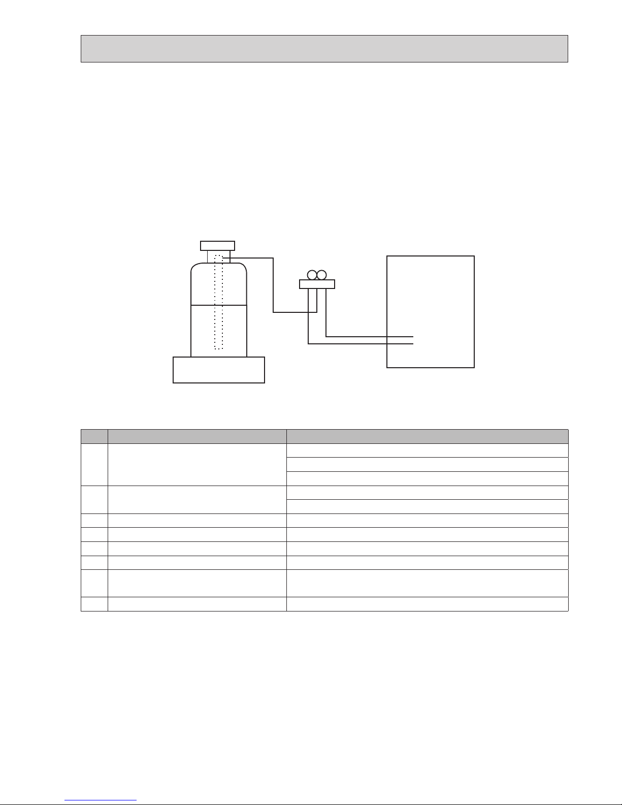
Tool
Tool
Conductor Conductor
Outline view Top view
<How to use TBO.1 to 4>
Connect them using either way as shown below.
1
3
5
7
X6
X7
1
3
CNBC
(GRY)
CNBH
(WHT)
10
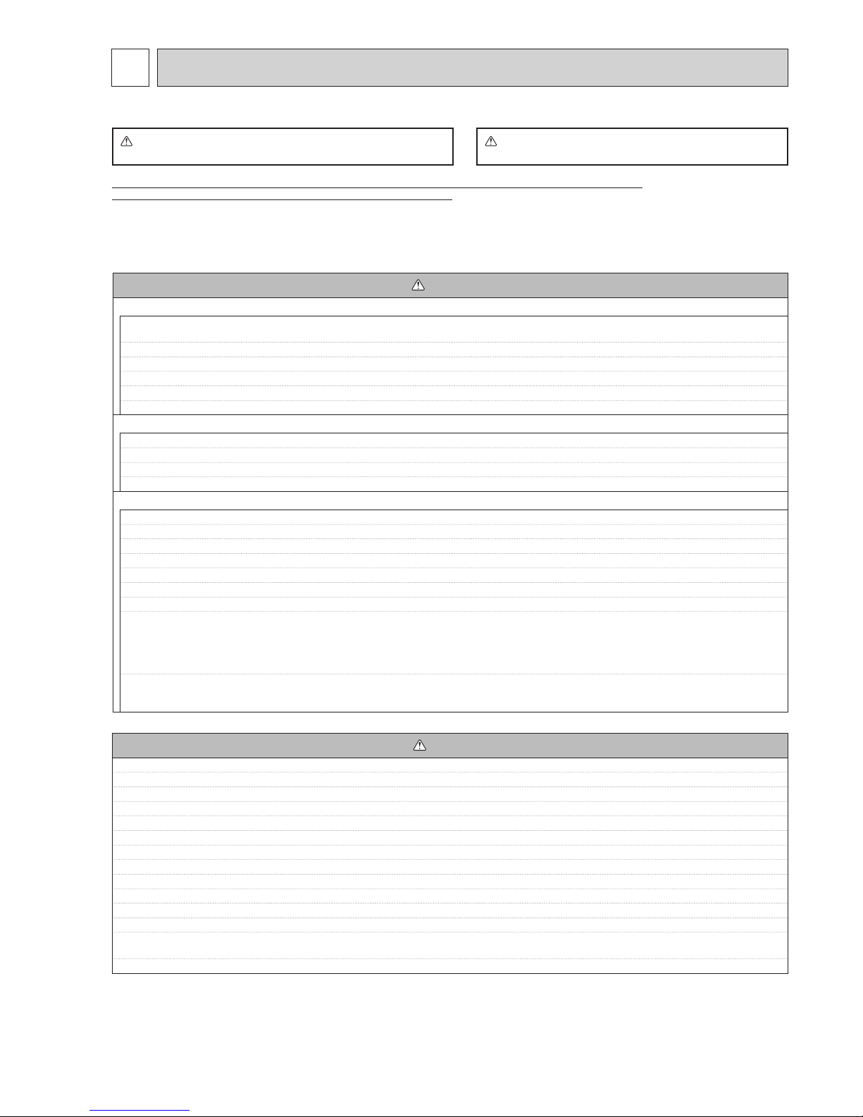
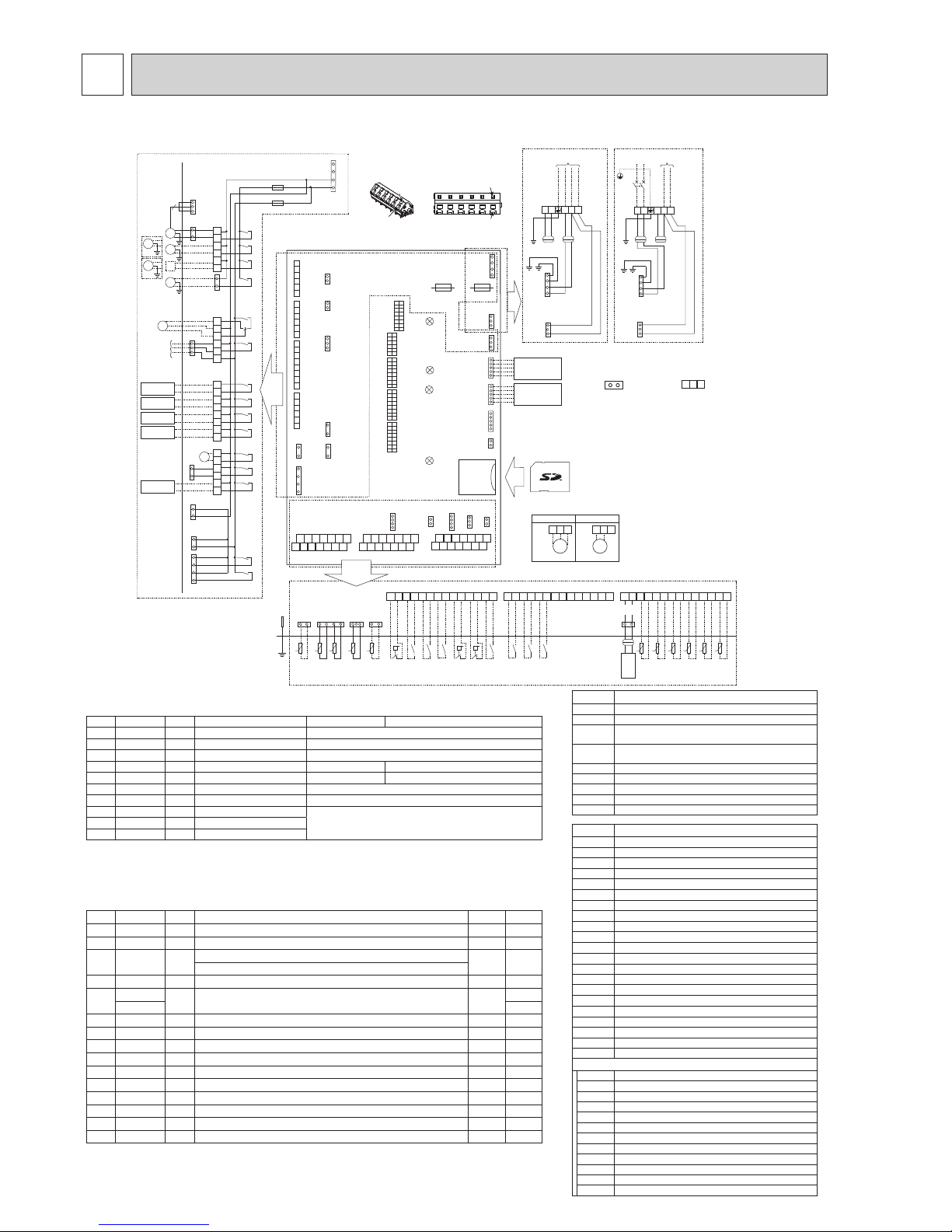
6WIRING DIAGRAM
6-1. EHSC-MEC, EHSD-MEC, ERSC-MEC
1. Symbols used in wiring diagram are,
: connector, : terminal block.
2. Indoor unit and outdoor unit connecting wires
have polarities, make sure to match terminal
numbers (S1, S2, S3) for correct wirings,
3. Since the outdoor unit side electric wiring may
change, be sure to check the outdoor unit electric
wiring diagram for service.
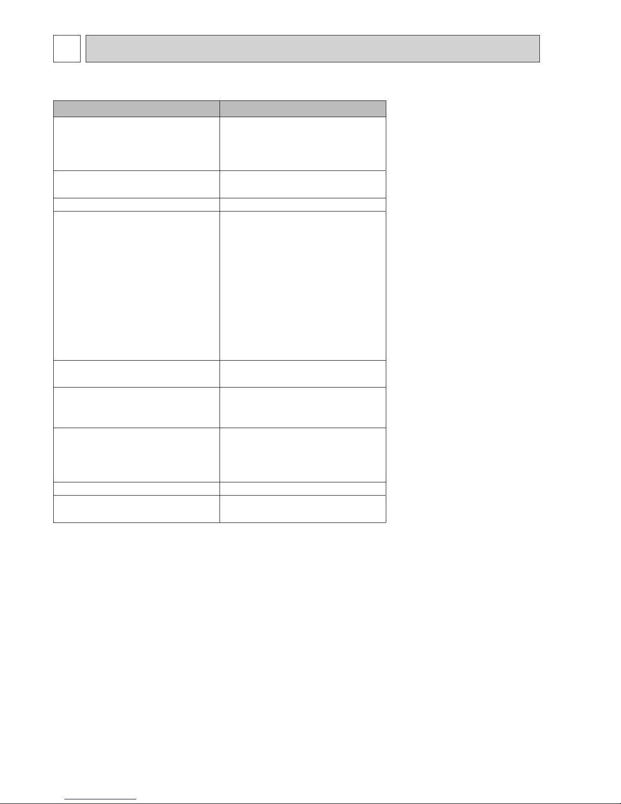
Symbol Name
TH1 Thermistor (Room temp.)(Option)
TH2 Thermistor (Ref. liquid temp.)
THW1 Thermistor (Flow water temp.)
THW2 Thermistor (Return water temp.)
THW5 Thermistor (DHW tank water temp.)(Option)
THW6 Thermistor (Zone1 ow temp.)(Option)
THW7 Thermistor (Zone1 return temp.)(Option)
THW8 Thermistor (Zone2 ow temp.)(Option)
THW9 Thermistor (Zone2 return temp.)(Option)
THWB1 Thermistor (Boiler ow temp.)(Option)
THWB2 Thermistor (Boiler return temp.)(Option)
IN1 Room thermostat 1 (Local supply)
IN2 Flow switch 1 (Local supply)
IN3 Flow switch 2 (Local supply)
IN4 Demand control (Local supply)
IN5 Outdoor thermostat (Local supply)
IN6 Room thermostat 2 (Local supply)
IN7 Flow switch 3 (Local supply)
IN8 Electric energy meter 1 (Local supply)
IN9 Electric energy meter 2 (Local supply)
IN10 Heat meter (Local supply)
FLOW TEMP. CONTROLLER (FTC5)
TBO.1−4
Terminal block <Outputs>
TBI.1
−
3Terminal block <Signal Inputs, Thermistor>
F1 Fuse (T10AL250V)
F2 Fuse (T6.3AL250V)
SW1
−
5DIP switch *See Table 3
X1
−
15 Relay
LED1 Power supply (FTC5)
LED2 Power supply (Main controller)
LED3 Communication (FTC5-Outdoor unit)
LED4 Reading or writing data to SD card
CNPWM
Pump speed control signal for MP1
CN108 SD card connector
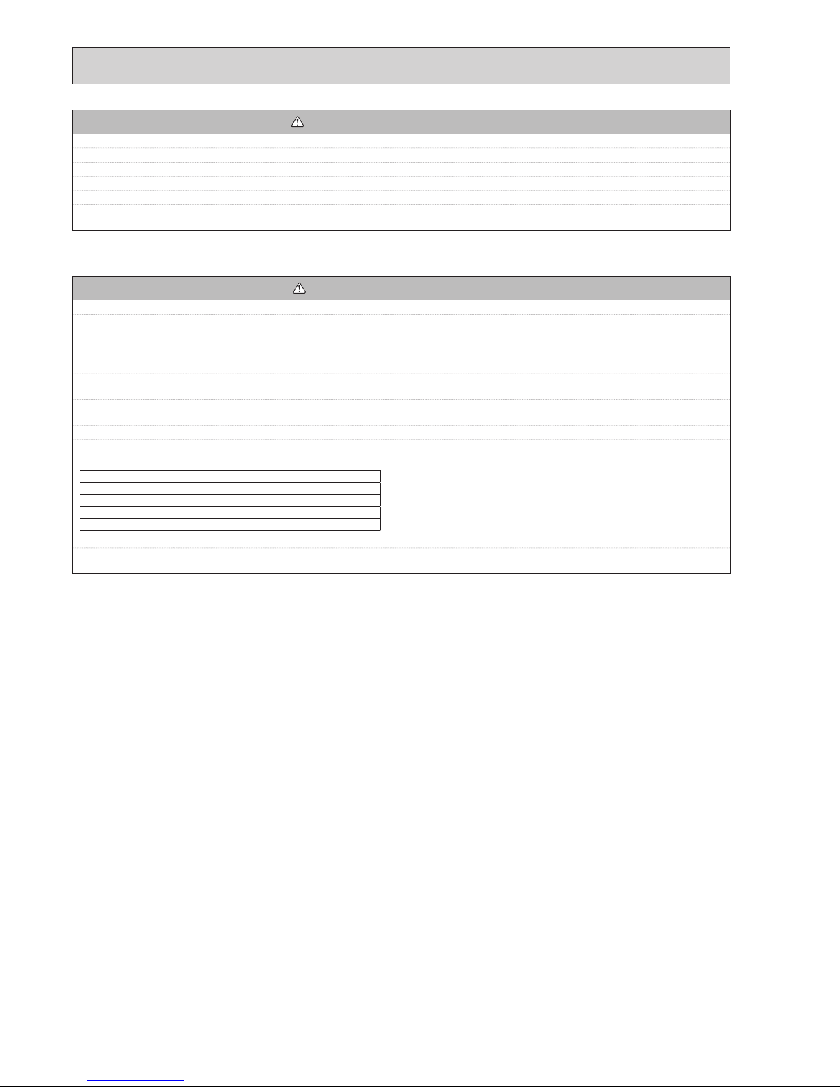
Table 1 Signal Inputs
Name
Terminal block
Connector
Item OFF (Open) ON (Short)
IN1 TBI.1 13-14 — Room thermostat 1 input Refer to SW2-1 in <Table 3 DIP Switch Functions>.
IN2 TBI.1 11-12 — Flow switch 1 input Refer to SW2-2 in <Table 3 DIP Switch Functions>.
IN3 TBI.1 9-10 — Flow switch 2 input (Zone1) Refer to SW3-2 in <Table 3 DIP Switch Functions>.
IN4 TBI.1 7-8 — Demand control input Normal Heat source OFF/ Boiler operation *2
IN5 TBI.1 5-6 — Outdoor thermostat input *1 Standard operation Heater operation/ Boiler operation *2
IN6 TBI.1 3-4 — Room thermostat 2 input Refer to SW3-1 in <Table 3 DIP Switch Functions>.
IN7 TBI.1 1-2 — Flow switch 3 input (Zone2) Refer to SW3-3 in <Table 3 DIP Switch Functions>.
IN8 TBI.3 1-2 — Electric energy meter 1
Refer to installation manual.IN9 TBI.3 3-4 — Electric energy meter 2
IN10
TBI.3 5-6 — Heat meter
*1. If using outdoor thermostat for controlling operation of heaters, the lifetime of the heaters and related parts may be
reduced.
*2. To turn on the boiler operation, use the main controller to select “Boiler” in “External input setting“ screen in the
service menu.
Table 2 Outputs
Name
Terminal block
Connector
Item OFF ON
OUT1
TBO.1 1-2 CNP1 Water circulation pump 1 output (Space heating/cooling & DHW) OFF ON
OUT2
TBO.1 3-4 — Water circulation pump 2 output (Space heating/cooling for Zone1) OFF ON
OUT3
TBO.1 5-6 — Water circulation pump 3 output (Space heating/cooling for Zone2) *1 OFF ON
2-way valve 2b output *2
OUT4
TBO.2 4-6 CNV1 3-way valve (2-way valve) output Heating DHW
OUT5
TBO.2 1-2 —Mixing valve output *1 Stop Close
TBO.2 2-3 Open
OUT6
—
CNBH 1-3
Booster heater 1 output OFF ON
OUT7
—
CNBH 5-7
Booster heater 2 output OFF ON
OUT8
TBO.4 5-6 — Cooling signal output OFF ON
OUT9
TBO.4 3-4 CNIH Immersion heater output OFF ON
OUT10
TBO.3 1-2 — Boiler output OFF ON
OUT11
TBO.3 3-4 — Error output Normal Error
OUT12
TBO.3 5-6 — Defrost output Normal Defrost
OUT13
TBO.4 1-2 — 2-way valve 2a output *2 OFF ON
OUT14
— CNP4 Water circulation pump 4 output (DHW) OFF ON
OUT15
TBO.3 7-8 — Comp ON signal OFF ON
Do not connect to the terminals that are indicated as “—” in the “Terminal block” eld.
*1. For 2-zone temperature control.
*2. For 2-zone valve ON/OFF control.
Symbol Name
TB1 Terminal block <Power supply, Outdoor unit>
MP1 Water circulation pump 1(Space heating & DHW)
MP2 Water circulation pump 2
(Space heating for Zone1)(Local supply)
MP3 Water circulation pump 3
(Space heating for Zone2)(Local supply)
MP4 Water circulation pump 4 (DHW)(Local supply)
3WV(2WV1)
3-way valve (2-way valve 1)(Local supply)
2WV2a 2-way valve (For Zone 1)(Local supply)
2WV2b 2-way valve (For Zone 2)(Local supply)
MXV Mixing valve (Local supply)


 Operation and maintenance instructions")