Mitsubishi Heavy Industries EEVKIT6-E-C/A User manual

EEVKIT6-E-C/A, /B
Manual No.'19・KX-T-336
TECHNICAL MANUAL
EEV-KIT
For single refrigeration system
Preliminary information, all of contents are subject to final confirmation by MHI.
In this manual, For multiple refrigeration system of EEV-KIT is shown.
Regarding the others manual please see below table.
General information '19 •KX-T-335
No.
'19 •KX-T-337
For multiple refrigeration system (EEVKIT6-E-M/A, /B, -C/A, /B)
Manual
updated February 24, 2021


-
1
-
'19 • KX-T-336
Contents
1. What is a single refrigeration system ....................................................... 2
1.1 System A ................................................................................................. 2
1.2 System B ................................................................................................. 5
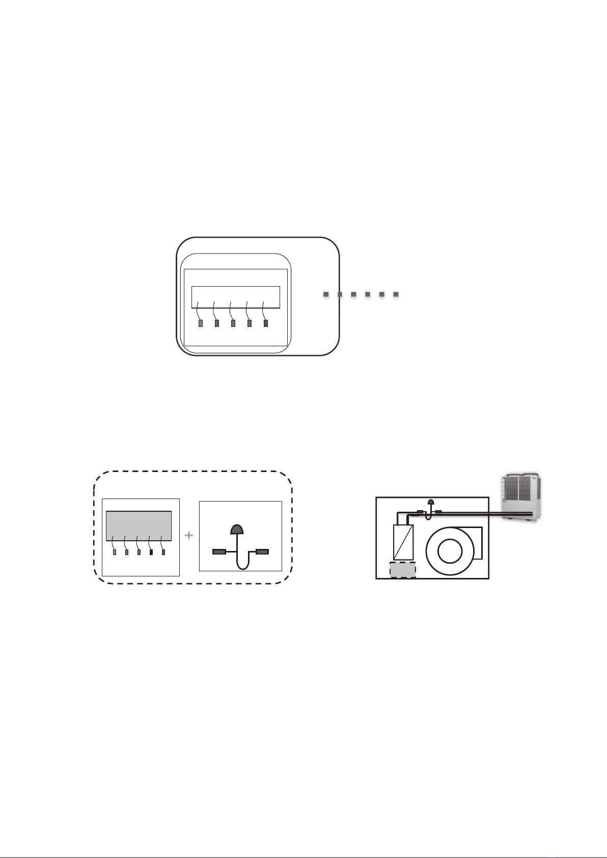
2. Components of a single refrigeration system ......................................... 8
3. Functions ..................................................................................................... 9
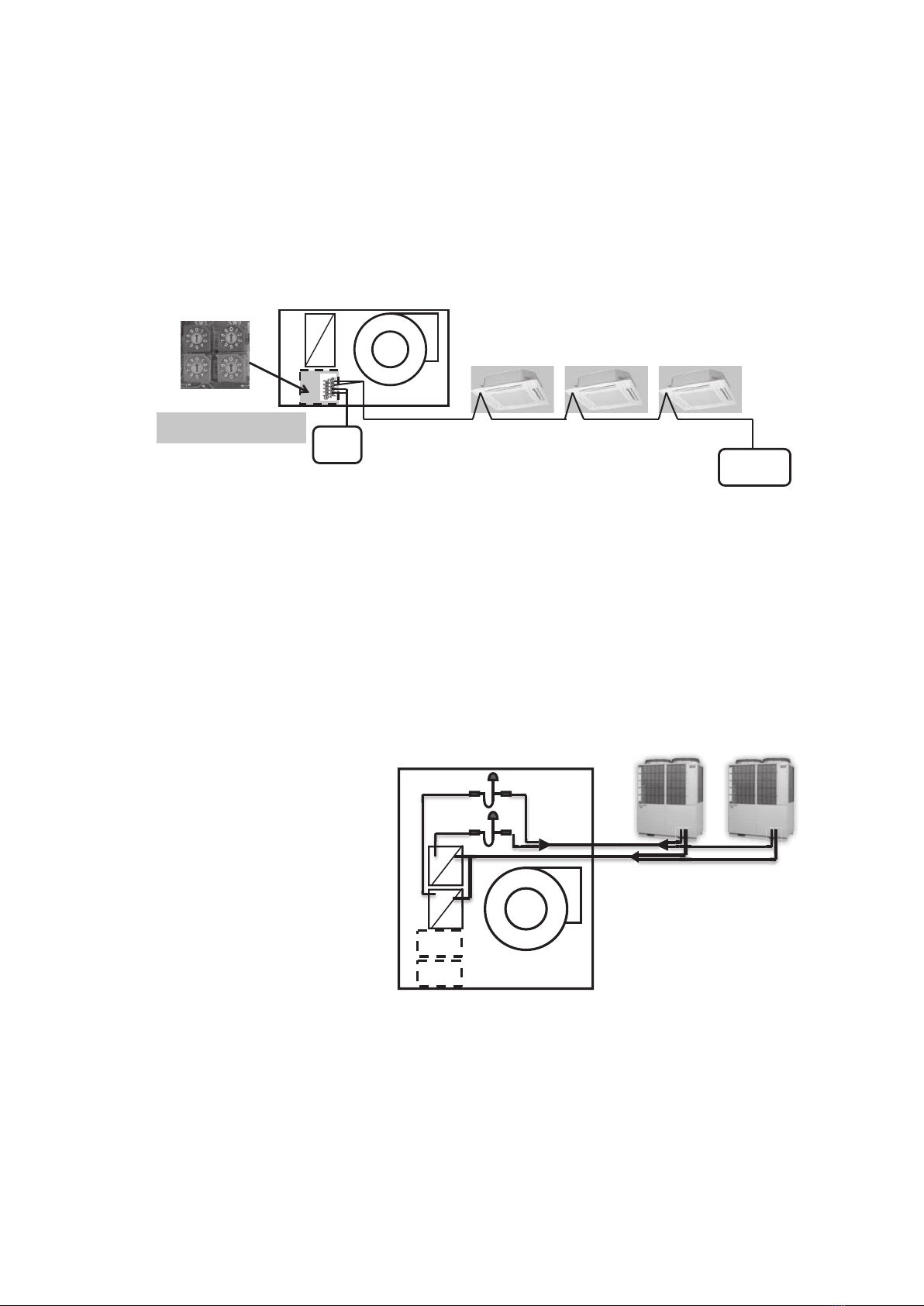
3.1 SW1- SW5 (Address setting) .................................................................. 17
3.2 SW6 (Model capacity selection) ............................................................. 18
3.3 SW7 (Function setting) ........................................................................... 18
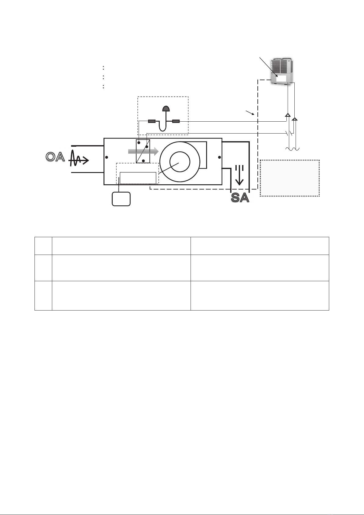
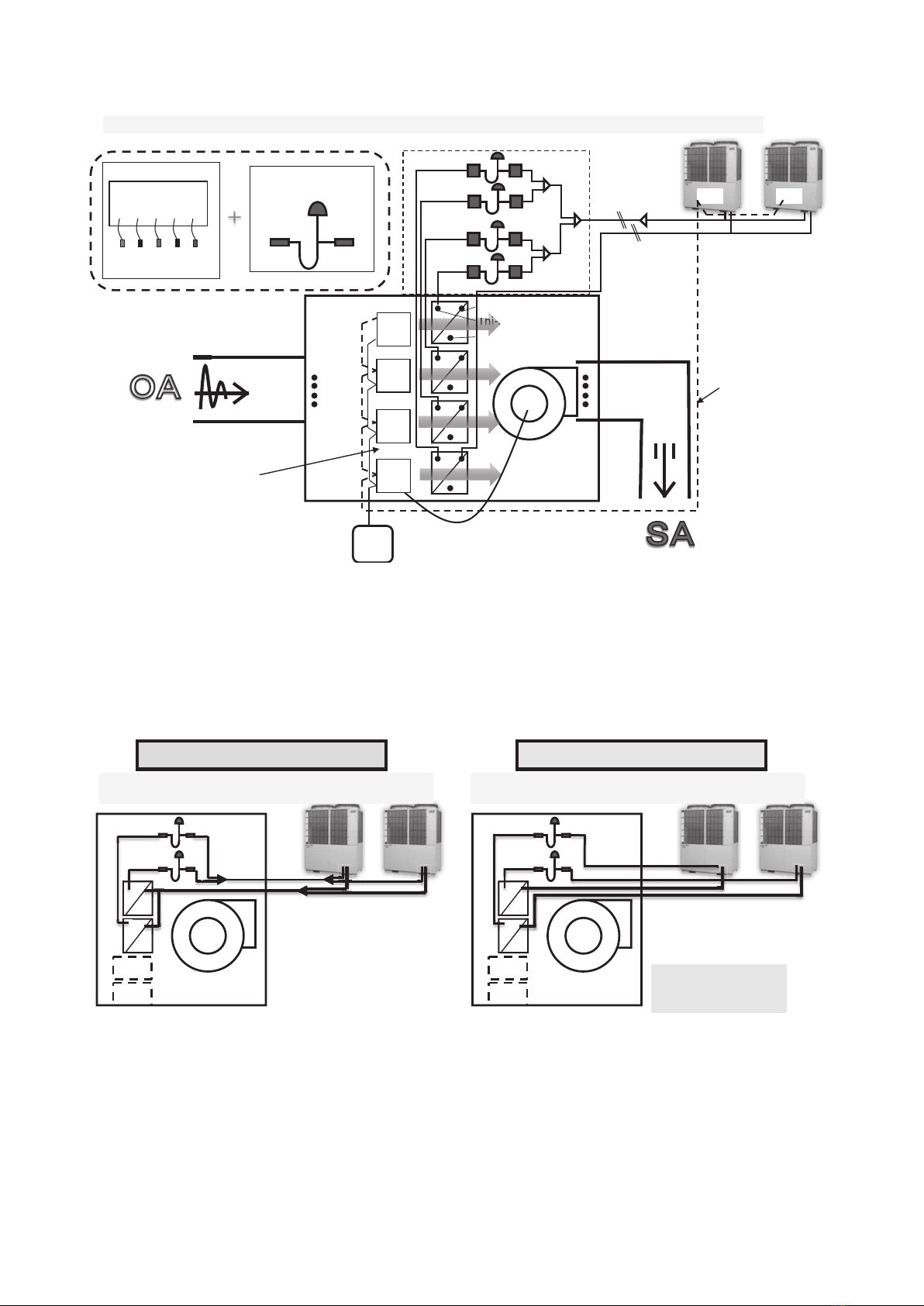
3.4 Switching return/supply air temperature control ................................. 19
3.5 Target supply air temperature adjustment (heating mode) ................. 26
3.6 Auto mode changeover temperature ..................................................... 26
3.7 Automatic supply air temperature adjust control ................................ 27
3.8 Free cooling control ................................................................................ 27
4. Outdoor unit ................................................................................................. 28
5. Summary ...................................................................................................... 31
6. Instruction of how to replace indoor unit control PCB ............................ 32

-
2
-
'19 • KX-T-336
1. What is a single refrigeration system
• A single refrigeration system is one that can have multiple outdoor units on one
refrigerant pipe work circuit.
• There are 2 types of EEV-KIT systems that can be built into the single refrigeration
system.
• System A : one EEV-KIT.
• System B : multiple EEV-KIT’s.
1.1 System A
This system has only one set of EEV-KIT built into one indoor unit with only one heat
exchanger. This system can be applied to an indoor unit whose capacity is up to
10HP.
• One EEV-KIT controls one EEV
• Maximum capacity is 10HP (equivalent to 280)
• Capacity setting of EEV-Control Box is required (default : 280)
Sensor (5pcs)
Thi-A
Thi-R1
Thi-R2
Thi-R3
Thi-AF
EEV-Control ASSY
EEVKIT6-E-C/A
Single refrigeraon system
FAN
EEV-Set
EEV-Control BOX
Sensors (5pcs)
Thi-A
Thi-R1
Thi-R2
Thi-R3
Thi-AF
EEV-KIT
EEV-Control box
EEV-Set
Strainer
EEV
Strainer
EEV-Control ASSY

-
3
-
'19 • KX-T-336
Total capacity limitation
Unit type Maximum indoor unit
capacity include EEV-KIT
1Air-conditioning mode
(STANDARD pressure control mode)
Same as normal KXE6 or KXZE1
(Max : 130% - 200%)
2Fresh air mode
(TYPE1 pressure control mode)100%
Fresh air mode
:
100% fresh air intake without total heat exchanger
(same as FDU-F units)
Sensors
Thi-A 䠖Sucon air temperature sensor
Thi-AF 䠖Supply air temperature sensor
Thi-R1,R2,R3 䠖Heat exchanger temperature sensor
Thi-R1
Thi-R2 Thi-R3
Thi-AF
Thi-A
EEV-Control box
䠢䠝䠪
EEV-Set
Strainer Strainer
To other I/U
h
㻾㻛㻯㻌
[Note]
Normal I/U can be
connected with EEV-KIT.
Capacity balance check
is required
01
O/U address
O/U address: 01
I/U address: 01
Signal line

-
4
-
'19 • KX-T-336
• All wiring for the 5 sensors, EEV-coil, operation command to indoor fan motor, remote
control and Superlink line must be connected to the EEV-Control box.
• Check both return/supply air temperature sensors. (Thi-A,AF) whether the temperature is
detected correctly.
• Confirm whether the heat exchanger temperature sensors(Thi-R1,R2,R3) detect the
correct temperature. Incorrect mounting of any sensor will cause problems with the
compressors.
• Check during commissioning
• The overcurrent relay and magnetic contactor for the fan motor should be provided
locally.
• Check whether the anomaly signal can be detected or not by inputting the overcurrent
anomaly signal from the fan motor to the EEV- Control box.
• Power source to the fan motor should be provided independently and not from the EEV-
Control box.
FAN
EEV-Set
EEV-Control box
Thi-R1
Thi-R2
Thi-R3
Thi-AF
Thi-A
EEV-coil
Fan motor
EEV-Control box
Power source line
The indoor fan motor ON/OFF signal
Overcurrent anomaly signal
FAN

-
5
-
'19 • KX-T-336
• The remote control for the KXE6 system (RC-E5) shall be provided separately if
required.
• Central control (SC-SL4) can be use for controlling together with other indoor units.
• The limitations of the address settings, capacity selection and cable length of the
Superlink line are the same as the KXE6 systems.
(See technical manual of KXE6 for details.)
1.2 System B
• System B is a system that has multiple EEV-KIT’s built into one indoor unit with
multiple heat exchangers on one refrigerant circuit.
• This system can be applied up to 48HP for KXE6 AHU capacity.
• This system can be applied up to 60HP for KXZE1 AHU capacity.
FAN
R/C
SL4
Address setting
EEV-Control box Signal line
FAN
EEV-Set ×2 sets
EEV-Control box ×2 sets

-
6
-
'19 • KX-T-336
• System B is a system that multiple EEV-KIT’s are built into one AHU and KXE6 or
KXZE1 outdoor units are used.
• However, multiple refrigeration systems used with one AHU can not be applied to system
B. In such cases, please use the master EEV-KIT for multiple refrigeration system
applications.
Thi-R1
Thi-R2
Thi-R3
Thi-AF
Thi-A FAN
R
h
i
T
h
i
-
R
EEV-Set
01 02
EEV slave control box
O/U Address
O/U Address
I/U Address 04
01
03
01
02
01
01
01
R/C
Signal line
EEV-Control BOX
Sensors (5pcs)
Thi-A
Thi-R1
Thi-R2
Thi-R3
Thi-AF
EEV-KIT
EEV-Control box
EEV-Set
Strainer
EEV
Strainer
EEV-Control ASSY
In case of a multiple refrigeration system, use the EEV-KIT for multiple refrigeration systems.
FAN
EEV-Set×2set
EEV-Control box ×2set
FAN
EEV-Set×2set
EEV-Control box ×2set
This system can be applied. This system can NOT be applied.
A Master control
is necessary.
Multiple refrigeration systemSingle refrigeration system
One refrigerant circuit Two refrigerant circuit

-
7
-
'19 • KX-T-336
1. The wiring connection method for each EEV-KIT is basically the same as that for system A.
2. All of the return/supply air temperature sensors for all the EEV-KIT’s shall be placed and
connected individually.
3. The wiring for the fan motor command signal should be connected to one of the EEV-
Control boxes.
4. The remote control wiring shall be connected to all the EEV-Control boxes.
• The Superlink line must be connected to all EEV-Control boxes and the outdoor unit
according to the standard rules of the KXE6 system.
• Set an address for each EEV-Control box.
FAN
Thi-R1
Thi-R2 Thi-R3
Thi-AF
×4
Thi-A
×4
FAN
RC
Fan motor wiring is connected
to a slave control
All controls are connected to
same remote control
Same position
FAN
Address setting

-
8
-
'19 • KX-T-336
2. Components of a single refrigeration system
Components of a single DX AHU refrigeration system
(1) Slave EEV Control ASSY (EEVKIT6-E-C/A, /B)
① Slave EEV-Control box
② 2 air sensor Assy. (Thi-A, Thi-AF)�
③ 3 heat exchanger sensor Assy. (Thi-R1, Thi-R2, Thi-R3)
(2) EEV-Set
(3) Outdoor unit for KXE6 or KXZE1 system
• Check the applicable models in the following tables.
• When controlling the AHU via a central control connected with normal indoor unit in
another refrigerant systems, it is recommend to connect the Superlink line to the central
control through Superlink adaptor (SC-ADNA-E) in order to control all EEV-KIT with
same settings and to prevent duplication of SL addresses.
SL4
FAN
R/C SL adaptor SC-ADNA-E
Superlink line
Remote
control line
Superlink
line
Central
control
KXZE1 series
Model Compatibility
FDC-KXZEN1 ○
FDC-KXZES1 ○
FDC-KXZPE1 ○
FDC-KXZME1 ○
FDC(S)-KXZE1 ○
FDCL-KXZE1 ○
FDC-KXZXE1 ○
FDC-KXZE1M ○
FDCB-KXZE1 ‑
FDC-KXZRE1 ‑
FDC-KXZRXE1 ‑
FDC-KXZWE1 ‑
KXE6 series
Model Compatibility
FDC(S)-KXEN6 ○
FDC(S)-KXES6 ○
FDC(S)-KXE6 ○
FDC(S)-KXE6M ○
FDC-KXRE6 ○ *
FDCB-KXE6 ‑
FDCR-KXE6 ‑
FDCH-CKXE6G ‑
FDCH-KXE6 ‑
*:Not possible to change the evaporating/condensing temperature

-
9
-
'19 • KX-T-336
3. Functions
(1) Outline
(
Use when heat exchanger
thermistor is installed.
)
Leaf spring
Thermistor for
heat exchanger
Discrimination tape
With/Without
Thermistor holder*
Thermistor holder : Provided locally
CNH
2
1
Thi-A
CNF
2
1
Thi-AF
3
2
1
Thi-R1
5
4
6
Thi-R2
Thi-R3
CNN
Top (Installation direction)
Label model name
Wiring label
(The back)
(Local mounting holes)
Thermistor
For Thi-R3
For Thi-R1,-R2
φ
φ9.52×t0.6
φ8.0×t0.6
Material
Copper tube
*
225
275
4-φ6
321
7.5
10
8
215
240
18
307
90
212
27.2
24
φ
Black
Yellow
8000
8000
8000
Yellow
Red
Leaf spring for heat exchanger
Thermistor for return air
Thermistor for supply air
Thermistor for heat exchanger
Notes
(1)Take note that this control box is not waterproof.
Do not allow water or dust to enter the control box.
Mount the control box firmly using the four holes shown in the figure and
confirm that it will not come loose due to vibration.
Use the tie-wraps included in the control box to fix the wiring. Confirm that
there is no tension on the wiring to the terminal blocks and that the wiring
connections are fixed tight in the terminal blocks.
The label for the model name is located on the left side of the control box.
Take note that the wiring diagram is located on the back of the lid.
If you do not use the lid of the control box, then use the wiring diagram that
comes with the control box.
Ensure a gap of more than 15mm at the top of the control box to
remove the lid of the control box.
Always install this control box in a secure location inside a locked enclosure.
(As there is danger of electric shock or incorrect operation)
Provide the following clearances above, below, to the right and to the left to ensure
enough space for ventilation and service work of the control box.
Bottom clearance
Top clearance
Left clearance
Right clearance
Front clearance
Min. 30mm・・・・・・・・・・・・・・・・・・・・・・・・・・・・・・・・・・・・・・・・・・Space for cooling
Min. 30mm・・・・・・・・・・・・・・・・・・・・・・・・・・・・・・・・・・・・・・・・・・ Space for cooling
Min. 100mm(Recommended length of 200mm or more)・・・ Space for wiring and service
Min. 30mm・・・・・・・・・・・・・・・・・・・・・・・・・・・・・・・・・・・・・・・・・・ Space for cooling
(2)
(3)
(4)
(5)
(6)
(7)
(8)
A
PCH000Z418
*:Not possible to change the evaporating/condensing temperature

-
10
-
'19 • KX-T-336
Hole for power source cable
Hole for communication cables
Wiring hole for total
enthalpy heat exchanger
Wiring hole for thermistor,
float switch and stepping motor
※1
※1
※1
※1
※1
※1
(AC220-240V 50Hz,
AC220V 60Hz)
(Remote controller X and Y cable,
Superlink A and B cable)
(Thi-A,Thi-AF,Thi-R1,R2,R3,FS,SM)
※2※3※4
※5(WHITE CONNECTOR)
※6
Not use
CNF
SW5 J1
SW7
SW6
Notes
This view is shown by removing the lid. The wiring diagram has been
pasted to the back of the lid. If you do not want to use the lid,
then use the wiring diagram supplied as an accessory.
※1
are the holes for accessory cable tie bands for fixing the site wiring.
※2
is a connector to be connected to thermistor Thi-A.
※3
is a connector to be connected to thermistor Thi-AF.
※4
is a connector to be connected to thermistors Thi-R1,R2 and R3.
※5
is a connector to be connected to the float switch FS.
※6
is a connector to be connected to the stepping motor SM.
(1)
(2)
(3)
(4)
(5)
(6)
(7)
A
PCH000Z418

-
11
-
'19 • KX-T-336
225
275
4-φ6
302
7.5
8
240
16
(67)
(Local mounting holes)
Notes
.
CNF
SW5 J1
SW7
SW6
When removing the sheet metal cover take care not to damage
the internal control box wiring.
After connecting the local wiring, confirm that there is no direct
tension of the local wiring onto the terminal blocks or the connectors
of printed circuit board (PCB).
If you are using the control box as shown in the figure,
take note the following points.
・
Ensure that the exposed high-temperature and the high-voltage parts
do not come into contact with any wiring.
・
Ensure that there is an air gap of more than 90mm above
the high-temperature and the high-voltage parts.
(1)
(2)
(3)
A
PCH000Z418

-
12
-
(2) Wiring diagram
PCH000Z420 A
'19 • KX-T-336
#
XR1
XR2
XR3
XR4
XR5
1
2
3
4
5
6
+12
CNT
X3
CNW0
RD
X6
1 753
X1
X2
Control PCB
DM
CNR2
9WH 31
YE
BL YE
X4
CNR
CNI
BL
SW6
SW5
131
CNB
SW2SW1
SW4SW3
SM
1
CNA
532 4
SW7
F(0.16A)
LED・3
LED・2
TB3
YX
1〜
M
M
Superlink(spare)
JSL1
CNK2
CNN
YE
CNW1
220V-240V
CNH
Thi-A
19V
CNW2
t° t°t°
24V
214321
t°
65
Thi-R3Thi-R2Thi-R1
6
2
BA
WH
CNK1
WH
(20S)
(SVH)
(SVG)
(SVE)
XB1
XB2
XB3
XB4
1
2
3
4
5
+12
CNT2
RD
TB1
WH
RD
AC220-240V 50Hz
Power source
CNU
1
3
BL
N
L
F(3.15A)
F(3.15A)
YE/GN
Earth
BK
Tri
345 6
52X1
XR2
51X1
C UH H ML
51X1
Heating
output
TB2
3
5
7
8
WH
CNM3
7
8
RD
YE
1
5
CNI2
WH
CNF
Thi-AF
t°
21
AC220V 60Hz
Single phase
Power
source
line
Power source line
between indoor units
Connector for branching
control of heat recovery
3-pipe system
RD
WH
RD
WH
RD
WH
BK
BK
BK
BK
GY
GY
BK
BK
BK
BK
BK
YE
BK
BK
RD
BR
RD
BR
BKWH
BL
RD
BL
BK
WH
RD
BL
OR
WH
RD
RD
RD
BR
WHWH
BR
WH
BK
BL
RD
BR
WH
1 2
52X1
3
5
Hi operation
YE
YE
Heat exch.(air)
<1> <2> <3> <4>
<5> <6>
CND
21
BL
CND1
YE
YE
Fan motor
error signal
YX
t°
Thc
YX
Signal line
(Shielded cord)
Single refrigeration system
7 8
52X2
3
5
Lo operation
Heat exch.(air)
<7> <8>
52X2
7
8
BL
YE
YE
YE
YE
YE
7 8
RD
12
12
FS
or
error signal
Float switch
error signal
FAN motor
To outdoor unit
(Operation)
(Heating)
(Compressor ON)
(Inspection)
(Remote operation input
For heat recovery 3-pipe system
:volt-free contact)
Free cooling
Remote
control
(RC−E4)
RC−E4:single only
(UHi, Hi) (Me, Lo)
Output
AHU fan motor
Input
Fan motor
error signal

-
13
-
'19 • KX-T-336
Input/output summary Capacity
TB1 *1 Power source terminal block AC300V, 25A
TB2 1,2 Output for fan
[ Fan speed : UHi, Hi ]
AC600V 15A AC250V, max 10A
DC125V, max 10A
3,4 Heating output
5,6 Input for AHU anomaly Dry contact
7,8 Output for fan
[ Fan speed : Me, Lo ]
AC250V, max 10A
DC125V, max 10A
TB3 *1 Remote control/ Superlink line
CNT *1 Available Relay capacity: DC12V max 160mA at total use
CNT2 *1 Available Relay capacity: DC12V max 160mA at total use
CND *2 Free cooling Output Relay capacity: DC12V max 75mA
*1 : Same as normal KXE6 indoor units
*2 : CND connector is included in control unit
Mark list
Mark Parts name
Single refrigeration system Multiple refrigeration system
CAN-Z Connector Connector
DM Drain pump motor Drain pump motor
F Fuse Fuse
FS Float switch Float switch
JSL1 Spare Superlink terminal setting (for spare) Spare Superlink terminal setting (for spare)
LED・2 Indication lamp (Green-Normal operation) Indication lamp (Green-Normal operation)
LED・3 Indication lamp (Red-Inspection) Indication lamp (Red-inspection)
SM Stepping motor (for electronic expansion valve)
Stepping motor (for electronic expansion valve)
SW1 Indoor unit address: tens place Slave box address: tens place
※1
SW2 Indoor unit address: ones place Slave box address: ones place
SW3 Outdoor unit address: tens place Outdoor unit address: tens place
SW4 Outdoor unit address: ones place Outdoor unit address: ones place
SW5-1 Switching PCB setting for single/multiple
refrigeration system (☆OFF=single/ON=multiple)
Switching PCB setting for single/multiple
refrigeration system (☆OFF=single/ON=multiple)
SW5-2 Indoor unit address: hundreds place( ☆OFF) Reserved (keep off)
SW6-1-4 Model capacity setting ( ☆ON) Model capacity setting (
☆
ON)
SW7-1 Test run, drain pump motor test (☆OFF) Reserved(keep off)
SW7-2 Target supply air temperature adjustment
(heating mode) (
☆OFF)
+15deg.C setting at supply air temperature
control in heating (☆OFF)
SW7-3 Switching return/supplyair temperature control
(☆OFF)
Switching the control method of refrigerant flow volume
(☆OFF=Super heat control , ON=Supply air temperature control)
SW7-4
Automatic supply air temperature adjust control (☆OFF)
Reserved (keep off)
TB1 Terminal block (Power source line) (□mark) Terminal block (Power source line) (□mark)
TB2 Terminal block (□mark) Terminal block (□mark)
TB3 Terminal block (Signal line) (□mark) Terminal block (Signal line) (□mark)
Thc Temperature sensor (Remote control)
Thi-A Temperature sensor (Return air) It is not used in the multiple system.
Thi-AF Temperature sensor (Supply air)
Thi-R1,2,3 Temperature sensor (Heat exchanger) Temperature sensor (Heat exchanger)
Tri Transformer Transformer
X1-3,6 Relay for FM Relay for FM
X4 Relay for DM Relay for DM
XR2 Relay (DC12V) Relay (DC12V)
52X1.52X2.51X1 Relay (AC200V) Relay (AC200V)
■mark Closed-end connector Closed-end connector
☆Factory default
※1 The method of setting the address of the multiple system is different than usual.
Refer to the technical documentation.
#

-
14
-
'19 • KX-T-336
Wiring connection example
1) FAN motor operation signal
The AHU fan motor should be controlled by the EEV-KIT control.
If the fan is controlled independently, it may cause oil return problems. (During oil return
operation, the fan should not operate.)
FAN
Fan motor
operation signal
Fan motor error signal
Normal
Error
: Open
: Close
Drain pan
Float switch
E9
51X1
52X152X2
Damper for free cooling
AHU Power source
EEV-KIT
Power source
(
UHi,Hi
) (Me,Lo)
TB1
TB2
TB3
Thi-R1 Thi-R2 Thi-R3
Thi-A Thi-AF
Single phase
Fan step control
The slave control has two relays for the fan motor control.
52X1 UHi , Hi
52X2 Me , Lo
Even if only one step is necessary, the wiring
connection for the other step is also required.
Fan speed is changed by control. (hot keep)
ON
OFF
OFF
ON FAN
I/U Fan signal UHi Lo
Fan motor ON OFF
Without wiring…
Necessary
TB2
PCB
Not matched

-
15
-
'19 • KX-T-336
2) FAN motor error signal
The AHU fan motor should be controlled by the EEV-KIT control.
If the AHU fan motor can not operate, the outdoor unit system must stop.
Normal Error
Open
Close
Close
Open
The fan motor error signal is sent to the float switch
connector(CNI).When the error signal is sent,“E16” is shown.
3) Float switch error signal
Please connect as follows if you attach the float switch to slave control.
CNI on PCB . When the error signal is sent, “E16” is shown.
Normal Error
Close Open
Prepare on site Prepare on site
#
56
51X1
TB2
7
8
RD
WH
RD
WH
WH
<5> <6>
Fan motor
error signal
56
51X1
TB2
7
8
RD
WH
RD
WH
WH
<5> <6>
Fan motor
error signal
CNI
BL
51X1
1
5
CNI2
WH
RD
RD
12
12
CNI
BL
51X1
1
5
CNI2
WH
RD
RD
12
12
FS
CNI
BL
51X1
1
5
CNI2
WH
RD
RD
12
12
FS
CNI
BL
51X1
1
5
CNI2
WH
RD
RD
12
12

-
16
-
'19 • KX-T-336
4) Signal for humidifier
Error code list
Display on
remote control
LED on indoor circuit board
Content
Red (checking) Green (normal)
OFF
Stays OFF
Keeps flashing
Normal
Stays OFF Stays OFF Fault in power source, indoor power off or one phase down
E1
Stays OFF Keeps flashing Fault on the transmission between indoor
circuit board and remote control
Not sure Not sure Indoor computer abnormal
E2 1-time flash Keeps flashing
Duplication of indoor address No.(can only be detected during operation)
Excess number of remote controls(can only be detected during operation)
E3 2-time flash Keeps flashing Outdoor power off or one phase down
There is no corresponding outdoor unit address.
E5 2-time flash Keeps flashing Fault on outdoor-indoor transmission
E6 1-time flash Keeps flashing
Indoor heat exchanger temperature sensor interrupted or short-circuit
E7 1-time flash Keeps flashing Return air temperature sensor interrupted or short-circuit
E16 1-time flash Keeps flashing Float switch activation (only with FS), Fan motor (Faulty)
E10 Stays OFF Keeps flashing Excess number of remote control connections
E11 Stays OFF Keeps flashing The master indoor unit is not set properly.
E12 1-time flash Keeps flashing
Superlink Indoor unit address switch
Indoor No. Outdoor No.
New specification
001-127 49
Old specification
0-47 48,49
48,49 0-47
E15 1-time flash Keeps flashing Indoor supply air temperature sensor interrupted or short-circuit
E18 1-time flash Keeps flashing The address configuration fault for master-slave indoor units.
E19 1-time flash Keeps flashing Indoor unit operation check/drain motor check mode faulty
E28 Stays OFF Keeps flashing Remote control temperature sensor anomaly
Over E30 Stays OFF Keeps flashing Outdoor unit checking
(
outdoor circuit board LED checking
)
E63 Stays OFF Keeps flashing Emergency stop
Indoor unit
1 2 34 5 67 8
External operation input
Total heat exchanger
External operation input
Humidifier
Error output
(Normal open)
Total heat exchanger
a) Wire connection example with total heat exchanger
●Make sure to connect wires so that the total heat
exchanger is operated synchronized with the
operation of EEVKIT.
●For details, refer to the installation manual and
the instruction manual of total heat exchanger.
Indoor unit
1 2 34 5 67 8
b) Wire connection example with humidifier alone
● The heating output 3-4 is output in heating mode
regardless of operation / stop.
Make sure to connect wires so that the humidifier
is operated synchronized with the operation of
EEVKIT.
Humidifier
HS
#

-
17
-
'19 • KX-T-336
SW7: For function setting
(See item 3.3)
SW1-SW4 and SW6 can be set according to the required specifications.
SW1-SW4:For address setting
(See item 3.1)
(Same method as the KXE6 indoor unit)
SW6: For capacity selection
(See item 3.2)
SW5: For address setting, etc.
(See item 3.1)
3.1 SW1-SW5 (Address setting)
Set address in the same manner as KXE6 orKXZE1 system.
*OFF: 100’s=0 ON : 100’s=1
SW5-1 should be kept OFF.
Automatic address setting can be used,
but we recommend to use the manual
address setting method.
Switch Contents
SW1 Rotary switch (Blue) Indoor address (10's)
SW2 Rotary switch (Blue) Indoor address (1's)
SW3 Rotary switch (Green) Outdoor address (10's)
SW4 Rotary switch (Green) Outdoor address (1's)
SW5-2 DIP switch Indoor address (100's) *

-
18
-
'19 • KX-T-336
3.2 SW6 (Model capacity selection)
Set the model capacity according to the heat exchanger capacity. The capacity setting
is the same as the KXE6 or KXZE1 indoor unit rule.
Default
3.3 SW7 (Function setting) ★Factory default
1. SW7-1 is the same function as for the KXE6 indoor unit.
Model capacity
22 28 36 45 56 71 90 112 140 160 224 280
SW6-1 OFF ON OFF OFF OFF OFF OFF ON OFF ON OFF ON
SW6-2 OFF OFF ON OFF ON OFF ON ON OFF OFF ON ON
SW6-3 OFF OFF OFF ON ON OFF OFF OFF ON ON ON ON
SW6-4 OFF OFF OFF OFF OFF ON ON ON ON ON ON ON
Switch Function On/Off Setting
SW7-1 Test run, drain pump motor
test
★Off Normal
On Test run
SW7-2
Target supply air temperature
adjustment
(Heating mode)
★Off Normal
On Target supply air temperature
reduces -12 deg.C
SW7-3 Switching return/supply air
temperature control
★Off Return air temperature
control
On
Supply air temperature control
SW7-4 Automatic supply air
temperature. adjust. control
★Off Invalid
On Valid
This manual suits for next models
1
Table of contents
Other Mitsubishi Heavy Industries Refrigerator manuals