-All legs can be telescoped in 5 stages
-5 usable attachment eyelets on the tripod head
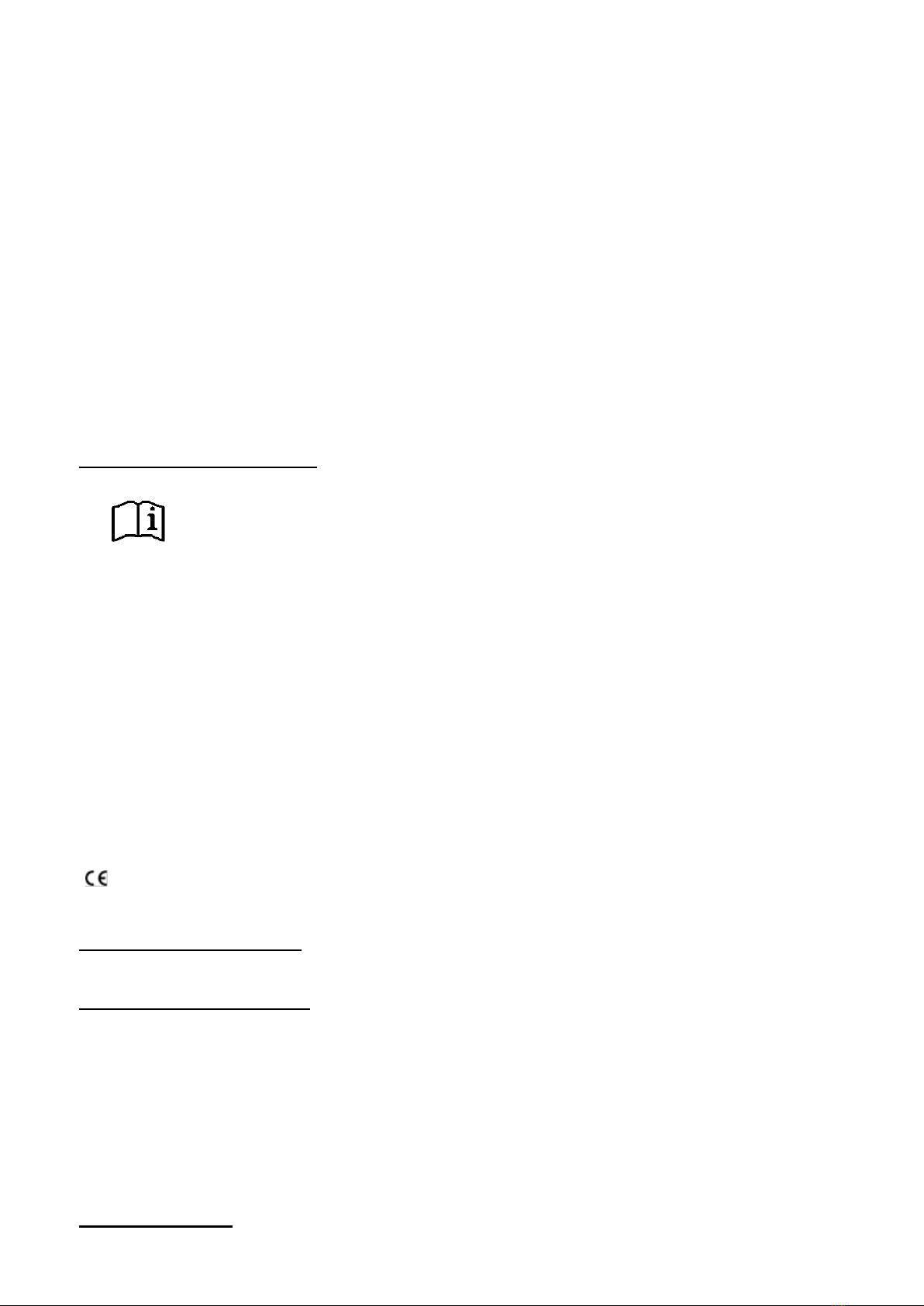
-Model with 3 folding feet
-1 set of guy ropes
-Height 215 cm
-Installation diameter 260 cm
-Weight 19.8 kg
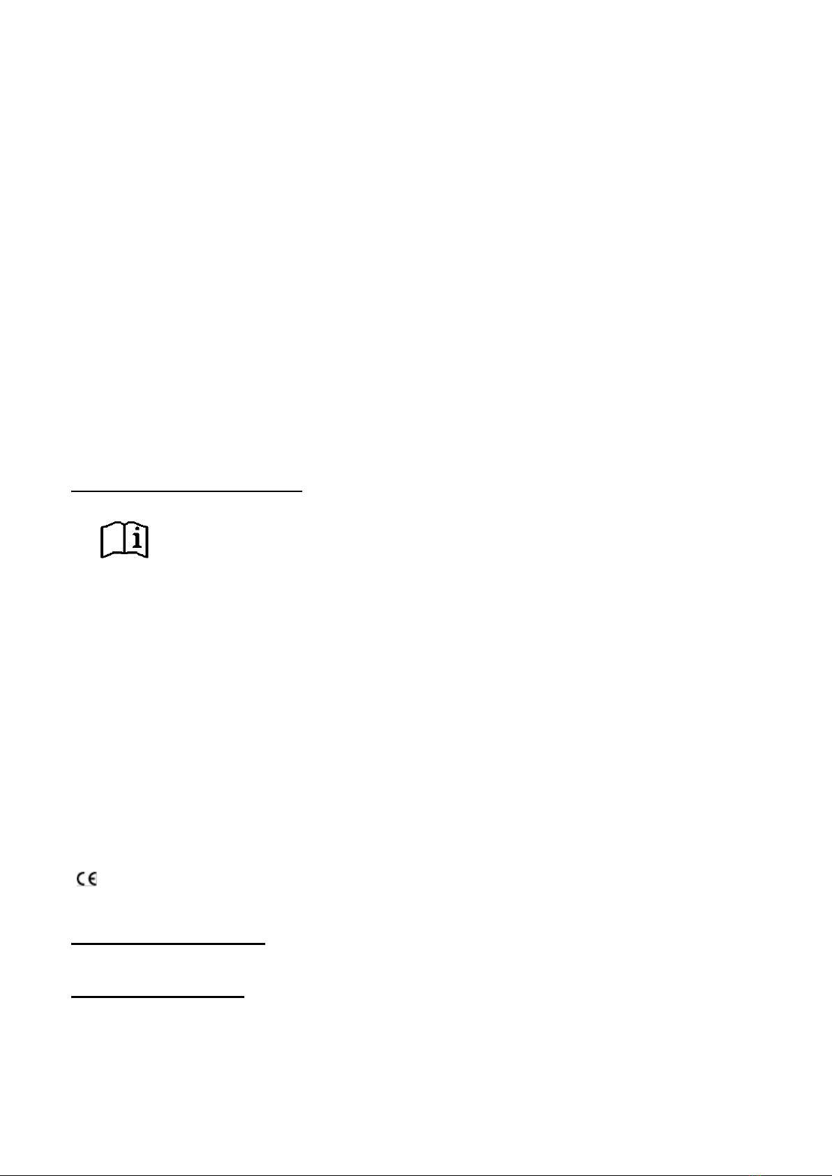
3 Installation
3.1 Version Tripod DB UNI and DB 500
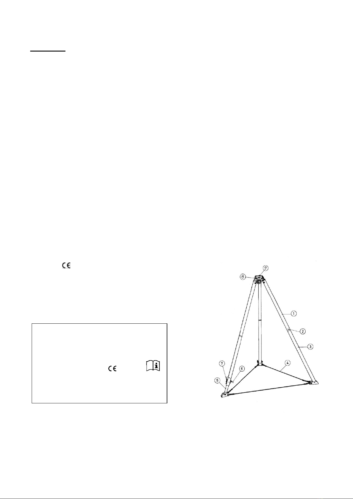
The tube tops item 1 (position numbers cf. Figure 1) are attached using the lock pin with a yellow
anchor eye item 8 on the tripod head item 9. Insert the tube bottoms item 3 into the tube top item 1 and
lock it with a spring catch item 2. Insert the telescopic foot or the telescopic feet item into the tube
bottoms and lock with the lock pin item 6 and spring catch item 7 in the desired position. Connect the
feet of the tripod to the wire cables item 4. Spread out the tripod until the wire cables item 4 are
tensioned. Alternative to the wire cables,the tripod legs can also be connected withspecial connection
tubes and clamps. A major prerequisite for the secure function of the anchor device is the safety of the
tripod. Uneven surfaces can be compensated for with the adjustment foot (feet) item 5. To do this,
slacken the wire pin item 7, remove the lock pin item 6 and bring the adjustment tube into the
appropriate position. Here a bore in the tube of the adjustment foot must be flush with the bore in the
bottom of the tube. Now insert the lock pin and secure with the wire pin while pulling outward. When
erecting the tripod, it should be ensured that the standing feet are lying flat on the ground with its
standing surface. For the round feet, ensure when erecting that the ball joints are not tensioned. The
ball joints are only to be tensioned when the standing areas of the round feet are lying flat on the
ground.
For the tripod DB UNI, the adjustment feet can also be inserted without the tube bottoms directly into
the tube tops and secured with lock pins and wire pins. As a result, the tripod can be used with one
half installation height.
3.2 Version of tripod DB UNI and DB 500
The tube tops item 1 (position numbers cf. Figure 1) are attached using the lock pin with a yellow
anchor eye item 8 on the tripod head item 9. Insert the telescopic foot or the telescopic feet item into
the tube bottoms and lock with the lock pin item 6 and spring catch item 7 in the desired position.
Connect the feet of the tripod to the wire cables item 4. Spread out the tripod until the wire cables item
4 are tensioned. Alternative to the wire cables, the tripod legs can also be connected with special
connection tubes and clamps. A major prerequisite for the secure function of the anchor device is the
safety of the tripod. Uneven surfaces can be compensated for with the adjustment feet item 5. To do
this, slacken the wire pin item 7, remove the lock pin item 6 and bring the adjustment tube into the
appropriate position. Here a bore in the tube of the adjustment foot must be flush with the bore in the
bottom of the tube. Now insert the lock pin and secure with the wire pin while pulling outward. When
erecting the tripod, it should be ensured that the standing feet are lying flat on the ground with its
standing surface. For the round feet, ensure when erecting that the ball joints are not tensioned. The
ball joints are only to be tensioned when the standing areas of the round feet are lying flat on the
ground.
The following applies to all versions of the tripod.
The arrest system for the fall protection of one person and/or the rescue device can now be attached
to the respective attachment eyelet of the tripod-head. As an alternative the rescue device can be
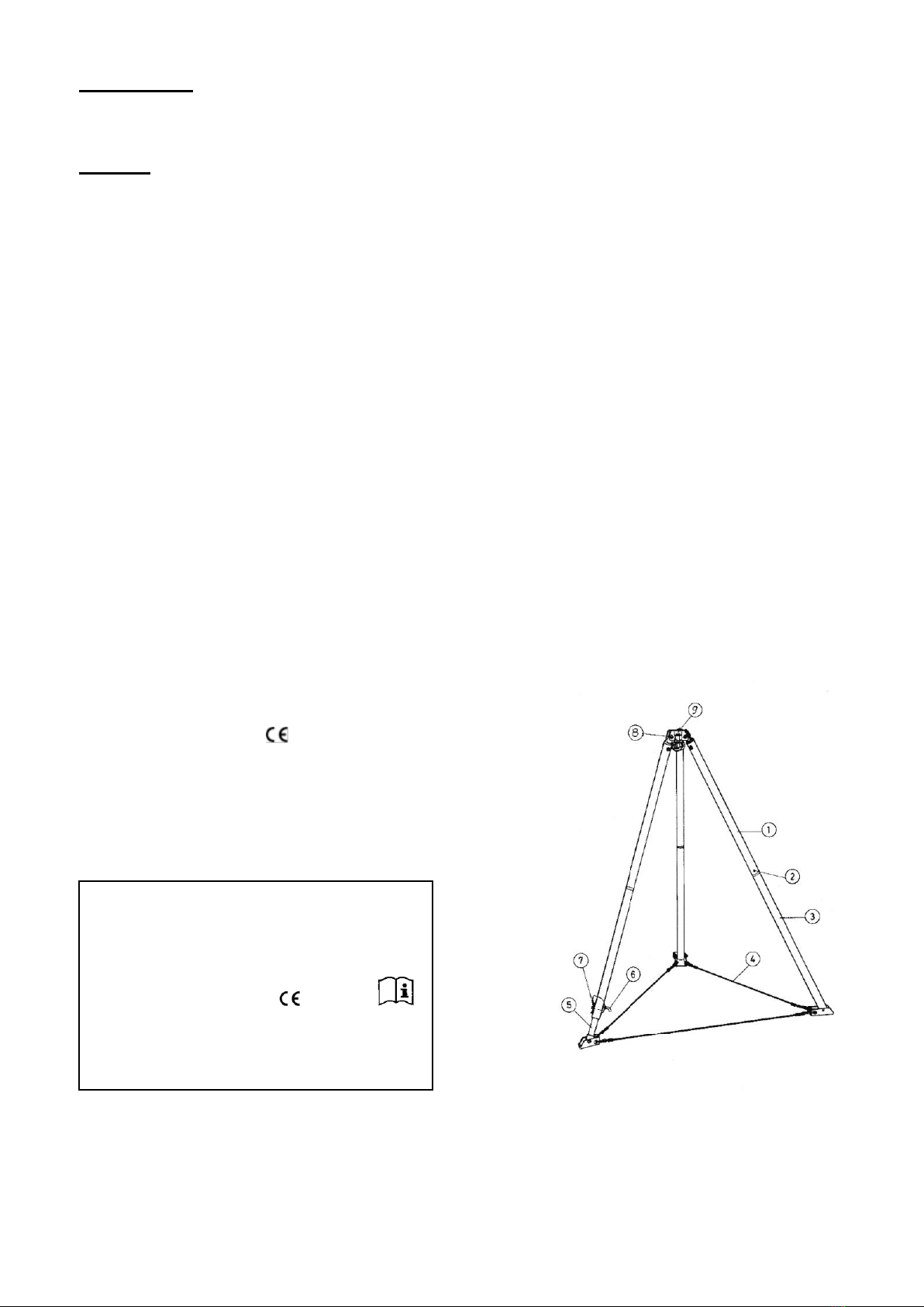
attached to one of the tripod’s legs by means of an adapter. To this end proceed as follows:
Unscrew the bolt with the black handle from the adaptor. Insert the descent device certified for use with
the adaptor withthe shackle (without the snaphook) in the aperture of the adaptor, re-introduce the bolt
into the adaptor passing it through the shackle and screw it tightly in the baseplate again. The descent
device has thus been attached to the adaptor. The adaptor can be equipped with either 2 clamps or 2
screw terminals .
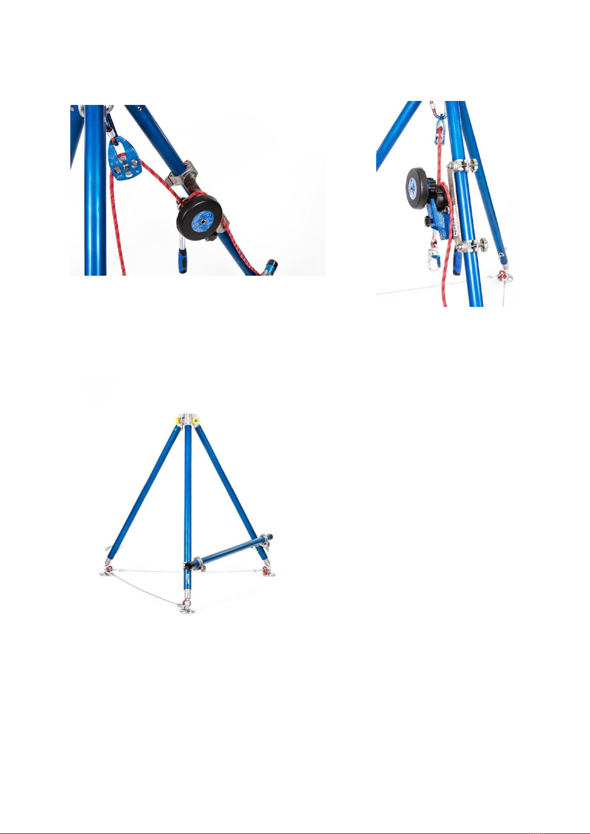
Procedure for the use of the clamps: open the clamps by unclasping and position on a leg of the tripod,
first close the middle clamp around the leg of the tripod, then position the upper clamp over the middle
clamp and close. The upper clamp is attached to an eyebolt which can rotate in the opened position.
Turning this element can adjust the clamping force. By turning right the force is increased and by
turning left the force is reduced. The clamps must close securely and the adaptor must be positioned
firmly on the tripod’s leg.