User’s Manual
99MAH017B
SERIES No.543
Remote Controller Operation Guide
This remote controller is used with the Digimatic Indicator ID-H0530/0560 (hereinafter referred to as ID-H indicator) to remotely
select one from among the Zero-setting, Preset-recall, Data output, and Switching Measurement modes.
It can also control up to 14 groups of ID-H indicators by setting their ID numbers.
Read this guide thoroughly prior to use along with the Digimatic Indicator User’s Manual (No. 99MAH016B).
1 Precautions for Use
Do not use this remote controller at sites under the following
environments.
・At a site where the ambient temperature is less than 0°C or
more than 40C°.
・At a site where the remote control is subject to splash of oil
and dust.
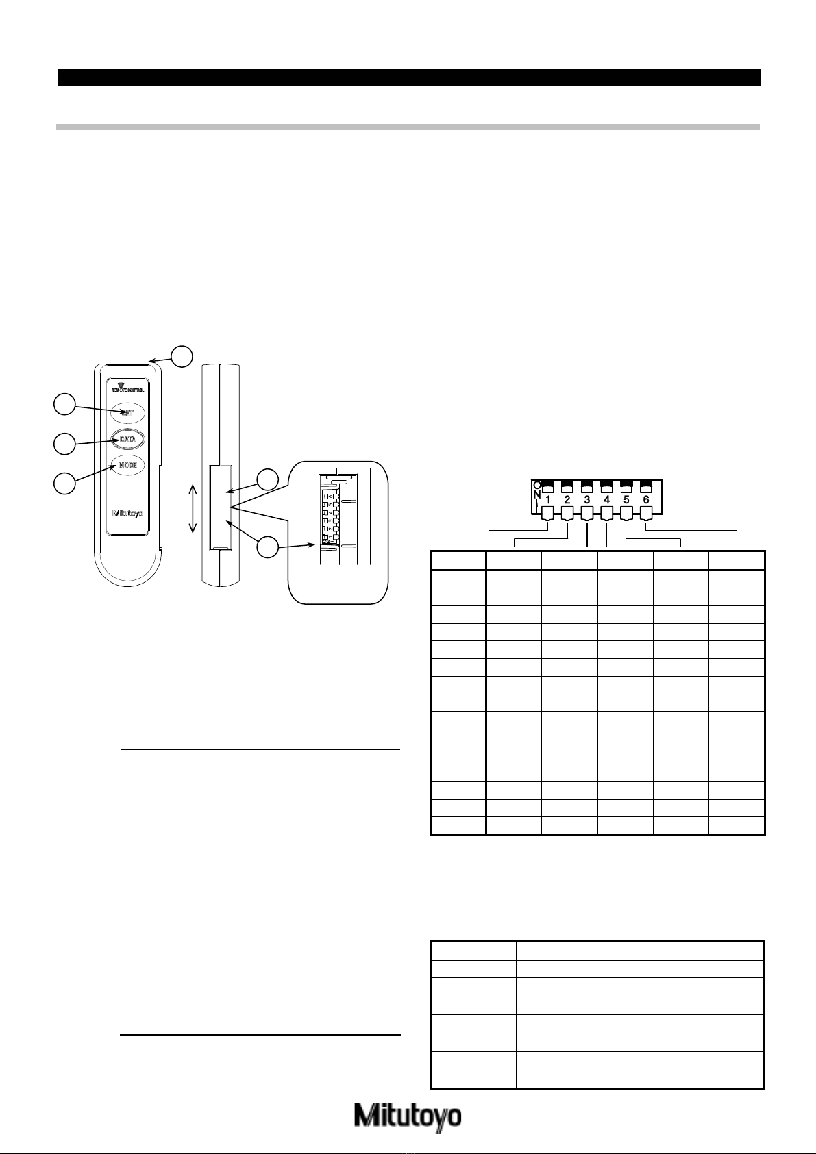
2 Name of Each Part (1) Signal transmitter
(2) SET key
(3) DATA key
(4) MODE key
(5) Battery cover
(6) DIP switch
3 Operating Procedure
3.1 Replacing the batteries
1. Slide the battery cover on the right side of this unit
upward to open it.
2. Insert the batteries in the correct orientation as shown
on the rear side of this unit.
3. Slide the battery cover downward to close it.
IMPORTANT •
•
•
•
•
The batteries are not loaded on this unit
at the time of purchase. Set the batteries
in place prior to use.
The batteries supplied at the time of
purchase are to check the functions and
performance. Note that the batteries
may not have a rated life.
If this unit will not be used for an
extended period of time (more than 3
months), take the batteries out and then
store them separately in a safe place.
When discarding or storing the batteries,
make a necessary process such as
wrapping around the + and – poles with
an insulating tape not to bring each
battery into contact with other metal or
battery.
When discarding the batteries, observe
your local government ordinance or
regulation.
3.2 Setting an ID No.
If the remote control ID No. is set to “0”, it can operate all ID-H
indicators irrespective of their ID Nos.
When controlling more than 2 units of ID-H indicators
separately, it is necessary to set a different ID No. for each
combination of an ID-H indicator and a remote control.
1. Open the battery cover on the right side of this unit to
remove the battery.
2. Operate the DIP switch at the back of the battery
compartment to set an ID No.
Set each DIP switch knob to ON or OFF with a sharp
tip such as tweezers.
For relationship between ID Nos. that can be set and
DIP switch settings, see the following table.
3. When the ID No. setup has been completed, reload
the batteries in place.
ID No. 2 3 4 5 6
0 OFF OFF OFF ON OFF
1 ON OFF OFF ON OFF
2 OFF ON OFF ON OFF
3 ON ON OFF ON OFF
4 OFF OFF ON ON OFF
5 ON OFF ON ON OFF
6 OFF ON ON ON OFF
7 ON ON ON ON OFF
9 ON OFF OFF OFF ON
10 OFF ON OFF OFF ON
11 ON ON OFF OFF ON
12 OFF OFF ON OFF ON
13 ON OFF ON OFF ON
14 OFF ON ON OFF ON
15 ON ON ON OFF ON
*
*
*
*
The DIP switch has been factory-set to ID No.0.
Raise each DIP switch knob upward to turn it ON.
If the ID No. is set other than above, the signal is outputted as ID No.0.
For information about the ID No. setup procedure of the ID-H
indicator, refer to ID-H Series Digimatic Indicator User’s Manual
(No.99MAH016B).
4 Specification
Part name Remote controller
Code No. 21EZA099
Controllable distance Approximately 6m
Power supply R03/LR03/AAAbattery:2pieces (3V)
Battery life More than 5000 times of key strokes
Operating temp. 0℃to 40℃
Storage temp. -10℃to 60℃
Net weight 60g
1
2
3 Open
Close
5
*Battery
compartment
4
1:OFF
6