Tekram Technology P6F40-B5 User manual

P6F40-B5 MAINBOARD
User’s Manual
REV: 1.1
Date: 01/97
* All other products names are trademarks or copyrights of their respective
owners.

TABLE OF CONTENTSTABLE OF CONTENTS
P6F40-B5 User’s ManualP6F40-B5 User’s Manual
22
INTRODUCTION.................................................................................4
Product Description...........................................................................................4
Item Checklist ...................................................................................................4
BOARD LEVEL FEATURES..............................................................5
INSTALLING THE CPU AND MEMORY.........................................8
Static Precautions..............................................................................................8
Installing the CPU.............................................................................................8
Connecting the CPU Cooling Fan......................................................................8
Setting the CPU Clock Selection Jumpers..........................................................9
Installing the Memory (DRAM SIMMS) ...........................................................10
SETTING THE JUMPERS..................................................................11
CONNECTIONS...................................................................................13
Power Supply Cables .........................................................................................13
Serial and Parallel Ports ....................................................................................13
IrDA-compliant infrared module connector .......................................................13
USB Connector..................................................................................................13
Keyboard Connector..........................................................................................14
PS/2 Mouse Connector ......................................................................................14
Floppy Drives....................................................................................................14
IDE Hard Drives and CD-ROMs .......................................................................14
MAINBOARD BIOS SETUP................................................................15
Using Setup.......................................................................................................15
Getting Help......................................................................................................15
A Final Note About Setup..................................................................................15
MAIN MENU....................................................................................................16
STANDARD CMOS SETUP.............................................................................17

TABLE OF CONTENTSTABLE OF CONTENTS
P6F40-B5 User’s ManualP6F40-B5 User’s Manual 33
BIOS FEATURES SETUP.................................................................................20
CHIPSET FEATURES SETUP..........................................................................23
POWER MANAGEMENT SETUP....................................................................26
PNP/PCI CONFIGURATION SETUP ...............................................................28
LOAD BIOS DEFAULTS .................................................................................29
LOAD SETUP DEFAULTS ..............................................................................29
INTEGRATED PERIPHERALS........................................................................30
SUPERVISOR PASSWORD AND USER PASSWORD SETTING ...................32
IDE HDD AUTO DETECTION ........................................................................33
HDD LOW LEVEL FORMAT ..........................................................................33
SAVE & EXIT SETUP / EXIT WITHOUT SAVING........................................34
BUILT-IN SYMBIOS SCSI BIOS .......................................................35
FLASH BIOS PROGRAMMING UTILITY .......................................40
DMI UTILITY ......................................................................................41
DC-310U PCI ULTRA SCSI ADAPTER .............................................42
þMAINBOARD DIAGRAMS
Board Level Features ........................................................................................5
Comprehensive Mainboard View .......................................................................7
Jumper Locations..............................................................................................11

INTRODUCTIONINTRODUCTION
P6F40-B5 User’s ManualP6F40-B5 User’s Manual
44
Product Description
The P6F40-B5 represents the highest level of technology available in PC Mainboards
today. Designed as a flexible, high-performance and cost-effective solution for System
Integrators and End Users alike, the P6F40-B5 provides the power and expandability to
meet the requirements of the most advanced operating systems and software applications.
Support for Intel®Pentium Pro®processors at speeds of up to 200Mhz is just the beginning.
The P6F40-B5 is designed to provide greater overall system throughput by utilizing the
latest in I/O technology. By incorporating such advanced features as Bus Mastering IDE and
Universal Serial Bus (USB) onto the mainboard, optimum system performance is assured
and system design and implementation is simplified.
Fully “Plug & Play” compatible via an Award BIOS, the P6F40-B5 facilitates easy system
configuration and peripheral setup. With support for up to 512MB of System RAM, Fast
Page mode, EDO, and BEDO, the P6F40-B5 is the ideal foundation for high-end computer
systems. The type of System RAM installed is auto detected by mainboard BIOS.
Item Checklist
Your mainboard package should include the items listed below. Damaged or missing items
should be reported to your vendor.
þThe P6F40-B5 mainboard
þFloppy disk drive ribbon cable
þ(1) IDE ribbon cable
þThis User’s Manual
þDiskette containing support software
for updating the FLASH BIOS and
IDE drivers
¨Optional PS/2 connector Module
¨Optional Infrared Module
¨Optional USB Module

BOARD LEVEL FEATURESBOARD LEVEL FEATURES
P6F40-B5 User’s ManualP6F40-B5 User’s Manual 55
1
1
1
1
SIMM 4
SIMM 3
SIMM 2
SIMM 1
PCI Bus 1
PCI Bus 2
PCI Bus 3
PCI Bus 4
PCI Bus 5
ISA Bus 1
ISA Bus 2
ISA Bus 3
1
1
11
1
1
7 8
2
1
1
1
1
2019
2
Socket8
1
1
1
1
1
2
3
4
5
6
7
8
9
1
0
11
1
2
1
3
1
4
1
5
16
17
18
19
1.
Keyboard BIOS
11.
DRAM SIMM sockets
2.
Mainboard BIOS
12.
Floppy connector
3.
USB connector
13.
Primary IDE connector
4.
Back Infrared (IR) connector
14.
Secondary IDE connector
5.
PS/2 mouse connector
15.
Front Infrared (IR) connector
6.
AT-keyboard connector
16.
Real Time Clock/Battery
7.
COM1 connector
17.
CPU socket
8.
COM2 connector
18.
ISA slots
9.
Printer port connector
19.
PCI slots
10.
Power connector
* Board Size: Baby AT 220mm x 280mm (8.66” x 11”)
Power connector

BOARD LEVEL FEATURESBOARD LEVEL FEATURES
P6F40-B5 User’s ManualP6F40-B5 User’s Manual
66
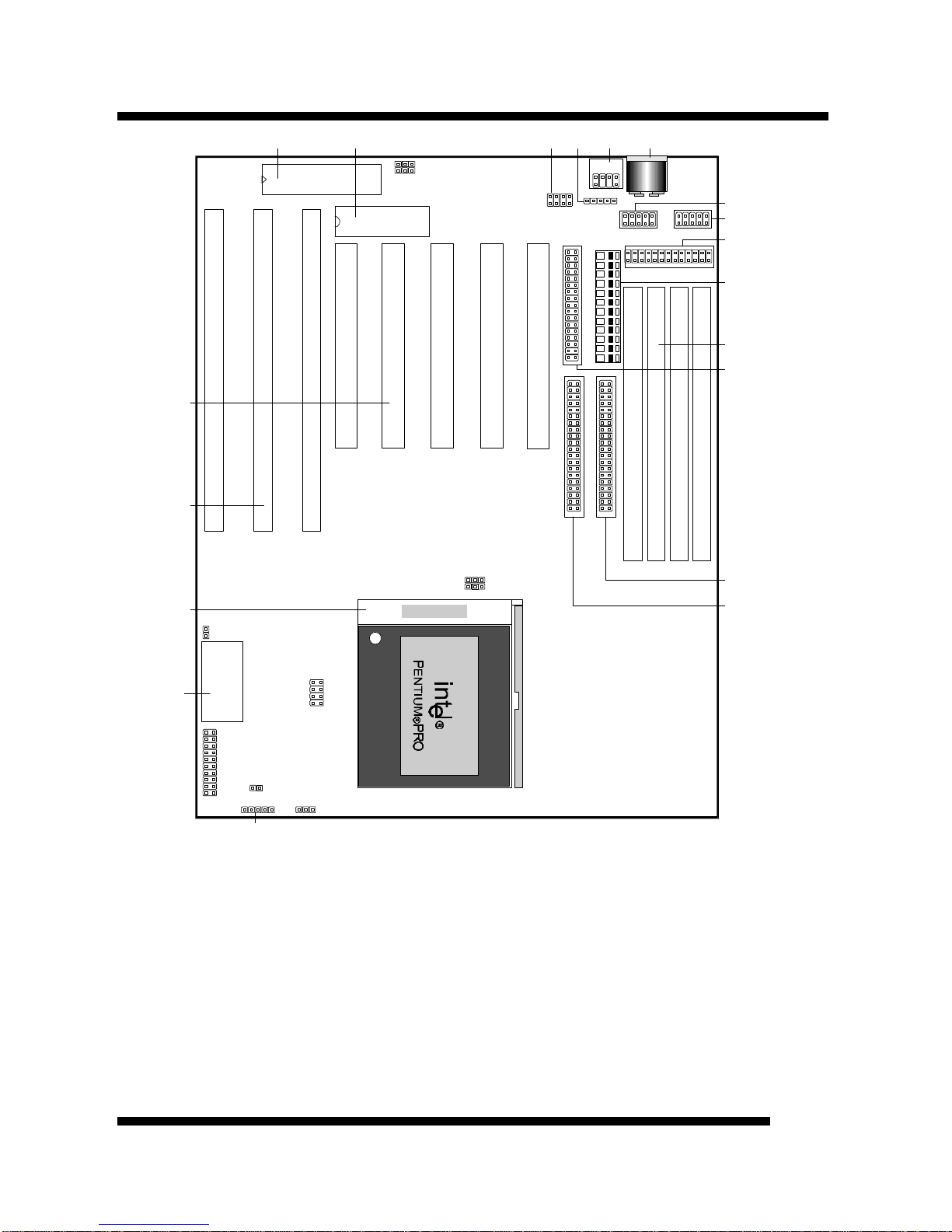
1. KEYBOARD BIOS: Firmware chip controlling keyboard operations.
2. MAINBOARD BIOS: Award BIOS supporting “Plug and Play”, DMI, Green PC
specification, on screen setup for Enhanced IDE and Multi-I/O. The BIOS is FLASH
Upgradeable via the AWDFLASH Utility.
3. USB CONNECTOR: A connector for an optional USB (Universal Serial Bus)
module is provided. This connector permits the connection of two USB peripheral
devices directly to the port without an external hub. USB is a new technology
supporting printers, fax modems and other telephony devices.
4. BACK INFRARED (IR) CONNECTOR: UART2 can also be used for the optional
Infrared Module, enabling wireless communication capability. A supplied bracket with
a single customized cable connects directly to the back infrared pin-header on the
mainboard. For computer cases that support a front IR device, see number 14.
5. PS/2 MOUSE CONNECTOR: Connector for optional PS/2 mouse bracket/connector.
If you are using a PS/2 mouse, you must purchase this bracket to insert into your PC
and connect to the PS/2 mouse pin-header on the mainboard.
6. AT-KEYBOARD CONNECTOR: Supports IBM compatible AT style keyboards.
7. COM1 CONNECTOR: High-speed UART compatible serial port.
8. COM2 CONNECTOR: High-speed UART compatible serial port. COM2 can be
directed to the Infrared Module for wireless connection capability.
9. PRINTER PORT CONNECTOR: EPP and ECP compatible parallel port.
10. POWER CONNECTOR: 12-Pin Power Connector.
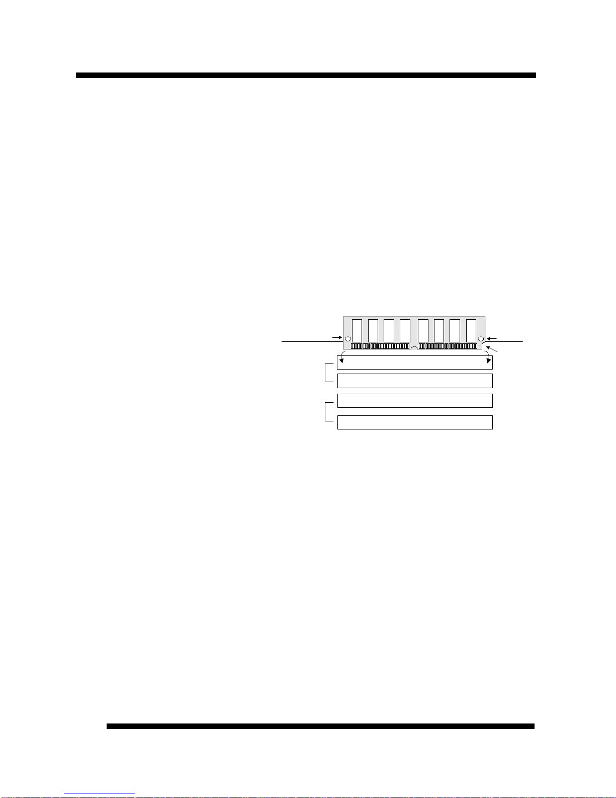
11. DRAM SIMM SOCKETS: (4) 72-pin SIMM sockets are provided to support a
maximum RAM memory capacity of 512 MB. SIMM types of either Fast Page Mode
(FPM), Extended Data Output (EDO) or Burst EDO (BEDO) are supported and
automatically detected by the BIOS.
12. FLOPPY CONNECTOR: Built-in floppy controller supports (2) 5.25" or 3.5"
(1.44MB or 2.88MB) floppy drives.
13. PRIMARY IDE CONNECTOR: Connector for first IDE channel. The on-board PCI
Bus Mastering IDE controller features support for DMA Mode 2 and PIO Modes 3 and
4 for faster data transfer rates. (2) Connectors are provided for support of up to (4) IDE
devices on two channels. ATAPI Tape Drives and CD-ROMs are also supported.
14. SECONDARY IDE CONNECTOR: Connector for second IDE channel.
15. FRONT INFRARED (IR) CONNECTOR: This is convenient to system cases that
support a front IR connector.
16. REAL TIME CLOCK: Circuitry responsible for the system time and date.
17. CPU SOCKET: ZIF Socket 8 for Pentium Pro CPUs. This mainboard supports CPU
speeds of 150/166/180/200mhz for Intel.
18. ISA SLOTS: (3) 16-bit ISA slots
19. PCI SLOTS: (5) 32-bit PCI slots are provided.

BOARD LEVEL FEATURESBOARD LEVEL FEATURES
P6F40-B5 User’s ManualP6F40-B5 User’s Manual 77
Comprehensive Mainboard View
Real Time
Clock
MainboardBIOS
KeyboardBIOS
Floppy
IDE 0 (Primary)
IDE 1 (Secondary)
1
1Printer
Power Connector
COM2
COM1
1
1
SIMM 4
SIMM 3
SIMM 2
SIMM 1
PCI Bus 1
PCI Bus 2
PCI Bus 3
PCI Bus 4
PCI Bus 5
ISA Bus 1
ISA Bus 2
ISA Bus 3
Key-
board
PS/2
Mouse1
1
11
USB IrDA
(IR)
1
IrDA(IR)FanPower
JP1
JP2
JP3
JP4
J13
J14
JP51
7 8
2
1
HD LED(IDE)
CPU Clock ratio
JP6
1
ClearCMOS
J16
1
2019
Turbo
LED
SMI
Reset
Keyboard
Lock
Speaker
J15
12
Socket8
1
1
1
1
x2x4
x3x2.5
x3.5
66MHz
60MHz
JP3
JP4
BusClock
Super
I/O Enabled Disabled
PS/2
mouseEnabled Disabled
normal
Clear
12V
G
G
CPU Clockration(JP5)
x2
133
120 266
200 240
180 233
166 210
150
x3x4x2.5x3.5
BusClock
(JP3,JP4)
66MHz
60MHz
CPU
Clock
(MHz)

INSTALLING THE CPU AND MEMORYINSTALLING THE CPU AND MEMORY
P6F40-B5 User’s ManualP6F40-B5 User’s Manual
88
Static Precautions
Static electricity can be a serious danger to the electronic components on this mainboard. To
avoid damage caused by electrostatic discharge, observe the following precautions:
üDon’t remove the mainboard from its anti-static packaging until you are ready to install
it into a computer case.
üBefore you handle the mainboard in any way, touch a grounded, anti-static surface, such
as an unpainted portion of the system chassis, for a few seconds to discharge any built-
up static electricity.
üHandle add-in cards and modules by the edges or mounting bracket.
Installing the CPU
üWARNING: Pentium Pro CPUs require a fan to keep
them cool and prevent overheating. Fans designed
specifically for the ZIF Socket 8 are recommended.
These fans provide a metal bracket that “snaps on” to
the tabs on the socket, holding the fan and CPU
firmly in place and preventing the CPU from working
loose during shipping. Other Fans should be installed first before inserting the CPU
into its socket.
1. Locate the ZIF (Zero Insertion Force) Socket 8. This socket supports Pentium Pro
CPUs (150-200Mhz).
2. First open the socket by pulling the lever sideways, then upwards. Notice how the lever
locks in place when pressed all the way down.
3. The CPU must be inserted with the correct orientation. One corner of the CPU has a
“notch” and looks different that the other three. This corner is marked with a white dot
on top of the CPU. Align this corner in the opposite direction of the lever as shown in
the figure above. Insert the CPU, hold it down, and close the lever until it locks into
place.
Connecting the CPU Cooling Fan (JP13)
JP13 is a small 3-pin Header Connector that provides 12-Volt power for CPU
Cooling Fans. This is useful if your Fan provides this type of connector,
instead of the normal Molex-Type Power-Supply connector. Pin-2
corresponds to the RED power lead as shown:
WhiteDot
Lever
Lock
Socket8Socket8

INSTALLING THE CPU AND MEMORYINSTALLING THE CPU AND MEMORY
P6F40-B5 User’s ManualP6F40-B5 User’s Manual 99
Setting the CPU Clock Selection Jumpers (JP3-5)
After installing the CPU, you must set
the clock selection jumper to match the
frequency of the CPU. Find the Jumper
Blocks labeled JP3-4 and JP5 on the
mainboard (Refer to the diagram on
page 7). Set the jumper according to the
table below for the CPU frequency you are using.
The CPU Clock corresponds to the number marked on the CPU. The Bus Clock when
multiplied with the Ratio gives the CPU Clock.
Bus Clock (MHz) CPU Clock Ratio
60 66 x2 x2.5 x3 x3.5 x4
JP3
JP4 JP5
These jumpers automatically set the ISA Clock as well.
* If you are uncertain about the speed or voltage requirements of your particular CPU, you
should obtain Technical Documentation from the manufacturer. Such information is
available via the Intel WWW site.
CPU Clock
Ratio
Bus Clock
150MHz x2.5 60MHz
166MHz x2.5 66MHz
180MHz x3.0 60MHz
200MHz x3.0 66MHz

INSTALLING THE CPU AND MEMORYINSTALLING THE CPU AND MEMORY
P6F40-B5 User’s ManualP6F40-B5 User’s Manual
1010
Installing the Memory (DRAM SIMMS)
•The P6F40-B5 mainboard supports 72-pin SIMMS of three types:
•Fast Page Mode (Asymmetric or Symmetric)
•EDO (Extended Data Output)
•BEDO (Burst EDO)
•SIMM Sizes supported: 4MB, 8MB, 16MB, 32MB, 64MB, and 128MB
•A total of (4) SIMMS can be installed for a maximum RAM capacity of 512MB. (With
four 128MB SIMMS Installed)
•Minimum RAM capacity is 8MB (With two 4MB SIMMS Installed)
•SIMMS speed requirements: 70ns or 60ns
1. This mainboard contains (2)
SIMM Banks. Each bank consists
of (2) SIMM Sockets. Memory
must be installed two SIMMS
(1 Bank) at a time. The two
SIMMS in a bank must be
identical.
2. Install SIMMS 1 and 2 first. The
SIMMS must be oriented in the
correct way. There is a notch in one end of the SIMM. Align this notch as shown in the
Diagram below. Retainers on either side of the SIMM will hold it in place.
SIMM 4
SIMM 3
SIMM 1
SIMM 2
Mainboard
1
1
1
1
mounting
hole
notcheden
d
mounting
hole
1
Bank1
Bank0

SETTING THE JUMPERSSETTING THE JUMPERS
P6F40-B5 User’s ManualP6F40-B5 User’s Manual 1111
Jumpers are used on this mainboard to
select various settings and features. A 2-pin
jumper has two settings: Open and Short (or
Closed). The jumper is closed by placing the
Jumper Cap across the two pins, thereby
connecting them. 3-pin jumpers can be set
to pins 1-2 or 2-3 connected. Pin-1 is
labeled on the circuit board for these jumpers as shown:
JP1: Super I/O Selection - [1-2] Enabled / [2-3] Disabled. The onboard Super-I/O
controller (W83877F) can be disabled to allow the use of an add-on I/O controller. Set JP1
to pins [2-3] to disable the onboard Floppy Controller, Serial Ports, Parallel Port, and IrDA
support.
JP2: PS/2 Mouse on IRQ12 - JP2 enables or disables the on-board PS/2 mouse lead
connector. When closed, the port becomes active and uses IRQ12.
3-pin Jumper 2-pin Jumper
Pin 1-2 Open
Pin 2-3 Short
1
1
1
1
SIMM 4
SIMM 3
SIMM 2
SIMM 1
PCI Bus 1
PCI Bus 2
PCI Bus 3
PCI Bus 4
PCI Bus 5
ISA Bus 1
ISA Bus 2
ISA Bus 3
1
1
11
1
1
7 8
2
1
1
1
2019
2
Socket8
1
1
1
1
1
2
3
4
5
6
7
8
9
1.
2.
3.
4.
5.
6.
7.
8.
9.
JP1
JP2
JP3
JP4
JP5
J13
J16
J15
JP6

SETTING THE JUMPERSSETTING THE JUMPERS
P6F40-B5 User’s ManualP6F40-B5 User’s Manual
1212
JP3, 4: Bus Clock Selection - This jumper set is explained in detail on page 9.
JP5: CPU Clock Ratio Selection - This jumper set is explained in detail on page 9.
J13: CPU cooling fan connector - Hook the CPU cooling fan power connector to this
jumper, observing the correct polarity. Pin-2 corresponds to the RED power
lead as shown:
J16: IDE Activity LED - Hook the IDE LED lead to this jumper, with the
RED lead corresponding to Pin-1.
J15: System Functions Jumper Block
Pins [3 & 5] Turbo LED switch - The Turbo function is
not supported by this mainboard. Therefore, the Turbo LED
will always remain lit as long as the system power is on.
Pins [7 & 9] SMI suspend switch lead - If your system’s
case has a suspend switch, hook the lead from the switch to
pins 7 & 9 of J15. A suspend switch is used to save
electricity by putting the system into a suspend mode when
the computer is not being used. This switch could also be
used by the Turbo switch on the front of the system, since
this mainboard does not support that function. For this switch to be functional, it must
first be enabled in the Power Management Setup in the BIOS Setup utility.
Pins [17 & 19] Reset switch lead - Connects to the Reset Switch lead from the system’s
case. The reset switch is used to “cold-boot” the system without actually turning off the
power, reducing wear and tear on the power supply.
Pins [2, 6, 8, 10] Keyboard lock switch lead - Pins 2 & 6 connect to the Power LED
from the system’s case. Pins 8 & 10 connect to the case-mounted keylock switch.
Pins [14 & 20] Speaker connector - Connects to the Speaker lead from the system’s
case.
JP6: Clear CMOS RAM - When closed, the CMOS information is reset to default. All
user-entered information is cleared. To clear the CMOS, first turn the computer off, then
connect a jumper cap over the two pins for a moment. Remove the jumper and power the
system on.

CONNECTIONSCONNECTIONS
P6F40-B5 User’s ManualP6F40-B5 User’s Manual 1313
Power Supply Cables
The two cables from the standard 5-volt power supply
connect to the power connector on the mainboard (refer
to page 4). You must align the connectors on the power
cable at a slight angle to correctly fit them onto the
mainboards power connector. Then, press down on the
connectors to lock them in place. The (2) connectors
should be installed so that the BLACK wires meet in
the middle of the connector.
Serial and Parallel Ports
The cables from the supplied serial port connector bracket hook to the COM1 and COM2
connectors on the mainboard. Generally, the upper serial port on the bracket would be
configured as COM1 and the lower port as COM2. Make sure to orient Pin-1 marked on the
mainboard to the RED stripe on the ribbon cables.
The cable from the supplied parallel port connector bracket hooks to the parallel connector
on the mainboard. Make sure to orient Pin-1 marked on the mainboard to the RED stripe on
the ribbon cable.
IrDA-compliant infrared module connector
The IrDA connector bracket hooks directly to this connector on the
mainboard. This connector provides support for the optional wireless
transmitting and receiving infrared module. You must first configure
through the BIOS setup where UART2 is directed, COM2 or IrDA.
USB Connector
This 8-pin connector permits connection of two USB peripheral devices directly to the
system without an external hub.

CONNECTIONSCONNECTIONS
P6F40-B5 User’s ManualP6F40-B5 User’s Manual
1414
Keyboard Connector
This connection is for a standard IBM-compatible keyboard. May also be known as a 101
enhanced keyboard.
PS/2 Mouse Connector
If you are using a PS/2 mouse, you must purchase one bracket to
insert into your PC and a single customized cable to directly
connect to the PS/2 mouse pin-header on your mainboard.
Floppy drives
The on-board floppy controller supports (2) floppy disk drives with the floppy ribbon cable
provided. Make sure the RED stripe on the ribbon cable is oriented towards Pin-1. Notice
the “twist” between the sets of connectors on the floppy cable. The floppy drive “A”
position is at the END of the cable, whereas floppy drive “B” is hooked to one of the
connectors on the other side of the twist. The cable provides both “Edge” and “Pin”
connectors for both the A and B positions to match the connector on your floppy drives.
IDE Hard Drives and CD-ROMs
The on-board Enhanced IDE controller can support up to (4) IDE hard drives or other
ATAPI devices, such as CD-ROMs. This controller, as with all Enhanced IDE controllers,
consists of both Primary and Secondary ports. Each port has an associated connector and
cable which can support up to (2) ATAPI devices each.
All IDE devices have jumpers which allow the user to configure the device as either
“Master” or “Slave”. A Master device is one that is ALONE on the IDE cable, whereas a
Slave device is installed as a SECOND device on the same cable. Keep in mind that the
Master device will appear before the Slave device in the CMOS Setup, as well as the
Operating System software. *Refer to the device documentation for jumper settings.
The Secondary IDE port can be used for up to (2) additional ATAPI devices. Normally it’s
recommended that you connect your first hard drive to the Primary port, and the first CD-
ROM to the Secondary.
Make sure to align the RED stripe on the ribbon cable with Pin-1 on the mainboard IDE
connector. On most hard drives and CD-ROMs, the RED stripe should be oriented towards
the power connector of the device.

MAINBOARD BIOS SETUPMAINBOARD BIOS SETUP
P6F40-B5 User’s ManualP6F40-B5 User’s Manual 1515
About the BIOS
The Mainboard BIOS (Basic Input/Output System) acts as the bridge between your
Hardware (CPU, Disk Drives, Video, etc.) and Operating System Software (Windows 95,
OS/2 and so on…) The BIOS Setup (also called CMOS Setup) is where many hardware
configuration options are set and stored. This configuration information will remain in the
BIOS until it is changed, or cleared via the “Clear CMOS” jumper (see page 12).
CMOS (Complementary Metal Oxide Semiconductor) refers to the chip in which the BIOS
information is stored.
The P6F40-B5 mainboard features Award BIOS, which provides an easy to use Setup
program to aid in hardware configuration. In this section we will look at the various menus
and options contained in the Award BIOS Setup Program. This mainboard also features a
“Flash” BIOS. A Flash BIOS can be upgraded via software, thereby eliminating the need to
actually replace the “BIOS Chip” on the mainboard. Procedures for updating the BIOS
follow this section.
The Award BIOS installed in your computer system’s ROM (Read Only Memory) is a
custom version of an industry standard BIOS. This means that it supports Intel/Cyrix/AMD
processors in a standard IBM-AT compatible input/output system.
Using Setup
In general, you use the arrow keys to highlight items, press <Enter> to select, use the
PageUp and PageDown keys to change entries, press <F1> for help and press <Esc> to quit.
Getting Help
Pressing F1 will display a small help window that describes the appropriate keys to use and
the possible selections for the highlighted item. To exit the Help Window press <Esc>.
A Final Note About Setup
Not all systems have the same Setup. While the basic look and function of the Setup
program remains the same for all systems, individual motherboard and chipset combinations
require custom configurations. For example, you may find that your Setup main menu has a
different number of entries from the main menu displayed in this manual. These are simply
features not supported (or not user configurable) on your system.
The final appearance of the Setup program also depends on the Original Equipment
Manufacturer (OEM) who built your system. If your OEM has decided that certain items
should only be available to their technicians, those items may very well be removed from
the Setup program.

MAINBOARD BIOS SETUPMAINBOARD BIOS SETUP
P6F40-B5 User’s ManualP6F40-B5 User’s Manual
1616
•Shortly after the system is powered on, provided a CPU and sufficient RAM are
installed, you will see the message: Press DEL to enter SETUP.
•Press the DEL key to enter the Award BIOS Setup program.
MAIN MENU
Once you enter the Award BIOS CMOS Setup Utility, the Main Menu will appear on the
screen. The Main Menu allows you to select from several setup functions and two exit
choices. Use the arrow keys to select among the items and press <Enter> to accept and
enter the sub-menu.
ROM PCI/ISA BIOS (2A59F008)
CMOS SETUP UTILITY
AWARD SOFTWARE, INC.
STANDARD CMOS SETUP INTEGRATED PERIPHERALS
BIOS FEATURES SETUP SUPERVISOR PASSWORD
CHIPSET FEATURES SETUP USER PASSWORD
POWER MANAGEMENT SETUP IDE HDD AUTO DETECTION
PNP / PCI CONFIGURATION HDD LOW LEVEL FORMAT
LOAD BIOS DEFAULTS SAVE & EXIT SETUP
LOAD SETUP DEFAULTS EXIT WITHOUT SAVING
Esc : Quit ↑↓→←: Select Item
F10 : Save & Exit Setup (Shift) F2 : Change Color
Time, Date, Hard Disk Type...
Note that a brief description of each highlighted selection appears at the bottom of the
screen.

MAINBOARD BIOS SETUPMAINBOARD BIOS SETUP
P6F40-B5 User’s ManualP6F40-B5 User’s Manual 1717
STANDARD CMOS SETUP
This first menu is where the most basic hardware options are set. Information regarding the
system clock, IDE hard disks and floppy drives is stored and configured in this section. To
enter the Standard CMOS Setup, press the [ENTER] key with this menu highlighted.
Date (mm:dd:yy) : Fri, Apr 7 1996
Time(hh:mm:ss) : 00:00:00
HARD DISKS TYPE SIZE CYLS HEAD PRECOMP LANDZ SECTOR MODE
Primary Master : Auto 0 0 0 0 0 0 Auto
Primary Slave : Auto 0 0 0 0 0 0 Auto
Secondary Master : Auto 0 0 0 0 0 0 Auto
Secondary Slave : Auto 0 0 0 0 0 0 Auto
Drive A : 1.44M , 3.5in.
Drive B : None
Floppy 3 Mode Support: Disabled
Base Memory
: 640K
Extended Memory
: 15360K
Video : EGA / VGA
Other Memory
: 384K
Halt On : All Errors
Total Memory
: 16384K
ESC : Quit ↑↓→←: Select Item PU / PD / + / - : Modify
F1 : Help (Shift) F2 : Change Color
Upon entering the Standard CMOS Setup screen, you will see a screen like that below.
Again, notice that the bottom of the screen provides information relating to the highlighted
item as you move around the screen.
First, let’s set the system Date. Use the arrow keys to move to and highlight the “Date”
option. Select the Month by using the PgDn and PgUp keys. This is how most settings will
be configured. Then, move to the day, year and time via the arrow keys to finish setting the
system date and time.
Keep in mind that the system time is set in 24-hour time. With this method, 1PM is
represented as 13:00, 2PM as 14:00 and so on, with 00:00 corresponding to Midnight.
Pri Master, Pri Slave, Sec Master, Sec Slave - These four options relate to the (4) IDE
hard drives, CD-ROMs or other ATAPI devices that can be controlled via the on-board IDE
controller (review IDE Hard Drives and CD-ROMs on page 14). The “Pri Master” setting
specifies the first device on the primary IDE channel, “Pri Slave” - the second. Sec Master
and Sec Slave specify the devices on the secondary channel.
The first option available is the most important: Type. This is where you will specify the
type of device and how it is represented in the BIOS Setup. If the device is a hard disk or

MAINBOARD BIOS SETUPMAINBOARD BIOS SETUP
P6F40-B5 User’s ManualP6F40-B5 User’s Manual
1818
CD-ROM, generally the Auto option is the best choice for fast and easy setup of the hard
disk parameters. Let’s take a look at the difference between the Auto, User and Types (1-
45) options:
•Auto - This option instructs the BIOS to automatically configure the hard disk by
reading the parameters (cylinders, sectors, etc.) directly from the hard disk’s firmware.
Use this option if you are configuring a new hard drive, or one that has already been
formatted using the Auto option. Keep in mind that a hard drive is configured using a
certain set of parameters, those same parameters must be used for the life of the drive,
unless the drive is re-FDISKed using a different parameter set. (This procedure deletes
the old partition(s) on the drive and creates a new one, using the new parameters).
•User - This option allows you to manually
enter in the parameters of the hard drive.
Generally, this option would be used only if
the hard drive has already been formatted
with a certain set of parameters, and assured
consistency between the old and new
parameters is desired.
•Types 1-45 - Similar to the User option, these types should only be used if the exact
parameters for the hard drive are already entered as a specific type stored in the Setup
Program. Again, this would only be needed to assure that the parameters the drive was
formatted with and those it is using now, are identical. For new hard drives, the Auto
option is the preferred choice.
Mode - One of Enhanced IDE’s most important features is LBA (Logical Block Addressing)
Mode. This feature allows the use of larger hard drives by providing a way to bypass the
cylinder limitations imposed by many Operating Systems. LBA Mode is used to extend a
hard drive’s useable capacity by “remapping” the cylinders in a way that is acceptable to
these operating systems. For instance, a hard drive with the parameters of 2100 Cylinders,
16 Heads and 63 Sectors would be represented by LBA Mode as 525 Cylinders, 64 Heads
and 63 Sectors. (Notice that the Cylinders have been divided, and the Heads have been
multiplied, by a factor of 4)
On hard drives smaller in capacity than 528MB, LBA support is not needed. The option on
these devices is ignored, even if enabled. For hard drives greater than 528MB, LBA mode
should be enabled. The following rules apply:
•Operating Systems that do not use the FAT file system do not need LBA Mode, and
can use the Normal or Large Modes. Examples would be Netware and Unix.
•When configuring a new hard drive greater than 528MB in capacity, always make sure
LBA mode is enabled.
TYPE drive type
CYLS. number of cylinders
HEADS number of heads
PRECOMP write precom
LANDZONE landing zone
SECTORS number of sectors
MODE mode type

MAINBOARD BIOS SETUPMAINBOARD BIOS SETUP
P6F40-B5 User’s ManualP6F40-B5 User’s Manual 1919
•If you are using a hard drive that is over 528MB in capacity, but was already formatted
without using LBA mode, LBA support will be ignored even if it is enabled. This
assures correct access to the drive’s data.
•SCSI Hard Drives are NOT entered into the Mainboard BIOS Setup in any way.
The hard drive settings in the Standard CMOS Setup are only for drives connected to
the IDE Controller. So, if only SCSI drives were installed, all these settings would be
set to Type: None. SCSI Devices are configured via the SCSI controller’s BIOS.
Floppy Drives A: and B: - Select the Type for the A: and/or B: floppy drives. Remember,
floppy drive A: is the first drive, hooked to the END of the floppy ribbon cable. Floppy drive
B: is hooked up after the twist. Available settings are listed below:
None No floppy drive installed
360K, 5.25 in 5-1/4 inch PC-type standard drive; 360 kilobyte capacity
1.2M, 5.25 in 5-1/4 inch AT-type high-density drive; 1.2 megabyte capacity
720K, 3.5 in 3-1/2 inch double-sided drive; 720 kilobyte capacity
1.44M, 3.5 in 3-1/2 inch double-sided drive; 1.44 megabyte capacity
2.88M, 3.5 in 3-1/2 inch double-sided drive; 2.88 megabyte capacity
Floppy 3 Mode Support: - Enable this option ONLY for floppy drive(s) that support the
Japanese standard (1.2MB on 3.5” Diskette). Options: Disabled (Default), Both, Drive A /
B.
Video - This category selects the type of video adapter used for the primary system monitor.
Although secondary monitors are supported, you do not have to select their type in Setup.
EGA/VGA Enhanced Graphics Adapter/Video Graphics Array. For EGA, VGA, SEGA,
SVGA or PGA monitor adapters.
CGA 40 Color Graphics Adapter, power up in 40 column mode
CGA 80 Color Graphics Adapter, power up in 80 column mode
MONO Monochrome adapter, includes high resolution monochrome adapters
Error Halt - Determines whether or not the system will prompt you if an error is detected
during POST.
No errors The system boot will not be stopped for any error that may be detected.
All errors Whenever the BIOS detects a non-fatal error the system will be stopped
and you will be prompted.
All,
But Keyboard The system boot will not stop for a keyboard error; it will stop for all
other errors.
All, But Diskette The system boot will not stop for a disk error; it will stop for all other
errors.
All, But Disk/Key The system boot will not stop for a keyboard or disk error; it will stop for
all other errors.
Memory - This category is display-only. All memory detected by the POST (Power On Self
Test) of the BIOS is shown as the following types:

MAINBOARD BIOS SETUPMAINBOARD BIOS SETUP
P6F40-B5 User’s ManualP6F40-B5 User’s Manual
2020
Base Memory is the amount of conventional memory installed in the system. This value is
typically 640K for systems with 640K or more memory installed on the motherboard. The
Extended Memory is the amount of memory located above 1MB in the CPU's memory
address map. Other Memory refers to the memory located in the region between 640K and
1MB. This region can be used for shadowing as well as expanded memory in DOS.
BIOS FEATURES SETUP
This menu provides access to more advanced BIOS configuration settings that deal with
overall performance of the system and peripheral setup. This section allows you to configure
your system for basic operation. You have the opportunity to select the system’s default
speed, boot-up sequence, keyboard operation, shadowing and security.
Virus Warning : Disabled Video BIOS Shadow : Enabled
CPU L1 Cache : Enabled C8000-CBFFF Shadow : Disabled
CPU L2 Cache : Enabled CC000-CFFFF Shadow : Disabled
Quick Power On Self Test : Enabled D0000-D3FFF Shadow : Disabled
Hard Disk Boot From : Pri-IDE D4000-D7FFF Shadow : Disabled
System Boot Sequence : C, A D8000-DBFFF Shadow : Disabled
Swap Floppy Drive : Disabled DC000-DFFFF Shadow : Disabled
Boot Up Floppy Seek : Disabled
Floppy Disk Access Control : R/W
Boot Up NumLock Status : On
Boot Up System Speed : High
Typematic Rate Setting : Disabled
Typematic Rate (Chars/Sec) : 6
Typematic Delay (Msec) : 250
Security Option : System ESC : Quit ↑↓→←: Select
PCI / VGA Palette Snoop : Disabled F1 : Help PU/PD/+/- : Mod
Assign PCI IRQ For VGA : Disabled F5 : Old Values (Shift) F2 : Color
OS/2 Onboard Memory > 64MB : Non-OS2 F6 : Load BIOS Defaults
F7 : Load Setup Defaults
Virus Warning - When enabled, the BIOS will warn the user when any program attempts
to write to or format the boot sector. If an
attempt is made, the BIOS will halt the
system and the following error message
will appear:
You can accept or abort this operation.
Note: This feature is designed to guard against viruses that modify the boot sector on hard
disks. However, many disk diagnostic programs which attempt to access the boot sector
table, as well as partition and format programs, will also trigger this warning. If you will be
running such a program, you can disable Virus Protection first, or choose “Y” to accept the
boot sector modification when this message shows up.
! WARNING !
Disk boot sector is to be modified
Type "Y" to accept write or "N" to abort write
Award Software, Inc.
Table of contents
Other Tekram Technology Motherboard manuals

Tekram Technology
Tekram Technology P6E40-A4 User manual

Tekram Technology
Tekram Technology P5V30-B4 User manual

Tekram Technology
Tekram Technology P5T30-A4 User manual

Tekram Technology
Tekram Technology P6B40D-A5 User manual

Tekram Technology
Tekram Technology P5m4m User manual

Tekram Technology
Tekram Technology P6L40-A4E User manual

Tekram Technology
Tekram Technology S381M User manual

Tekram Technology
Tekram Technology P6BXA User manual

Tekram Technology
Tekram Technology P5T30-B4 User manual