iii EDH0387En1020 — 09/18
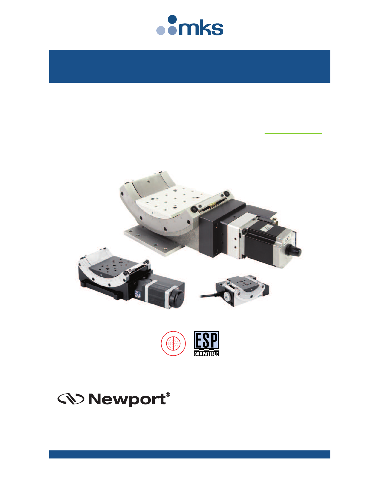
BG Series Goniometric Cradles
Table of Contents
Warranty .................................................................................................................ii
EC Declaration of Conformity...............................................................................v
Definitions and Symbols.......................................................................................vi
Warnings ...............................................................................................................vii
Caution .................................................................................................................viii
1.0 — Introduction.................................................................................1
2.0 — Description ...................................................................................2
2.1 Design Details ............................................................................................2
3.0 — Characteristics............................................................................3
3.1 Definitions..................................................................................................3
3.2 Mechanical Specifications .......................................................................4
3.3 Load Specification Definitions.................................................................4
3.4 Load Characteristics and Stiffness .........................................................4
3.5 Goniometric Cradle Weights ...................................................................5
4.0 — Drives and Motors ....................................................................5
4.1 Stepper Drive Versions ............................................................................5
4.2 DC-Servo Drive Versions ..........................................................................6
4.3 Sensor osition..........................................................................................7
4.4 Feedback Signal osition .........................................................................8
4.5 BGS inouts ...............................................................................................9
4.6 MSCABLE-3 Cable......................................................................................9
4.7 BGM inouts ............................................................................................10
4.8 MCAB-3 Cable ..........................................................................................10
5.0 — Connection to Newport Controllers ..............................11
5.1 Warnings on Controllers ........................................................................11
5.2 Connection...............................................................................................12
5.3 Cables .......................................................................................................12
5.4 MSCABLE-3 Cable....................................................................................12
5.5 MCAB-3 Cable ..........................................................................................13
6.0 — Connection to non Newport Electronics.....................14
6.1 Connections.............................................................................................14