• Switch on and check for correct operation
This driver is equipped with an output voltage adjuster (+V ADJ) which can increase or decrease the output
voltage by approximately 10%. No adjustment should be necessary, but should the driver be loaded to its total
capacity the voltage can be trimmed to help prevent overload; alternatively increasing the output voltage can
help to compensate for voltage drop on the load side.
INSTALLATION & MAINTENANCE MANUAL
These instructions should be read carefully and retained after installation by the end user for future reference
and maintenance.
These instructions should be used to aid installation of the following products:
24DC100M / 24DC150M / 24DC200M
SAFETY
•This product must be installed in accordance with the latest edition of the IEE Wiring Regulations
(BS7671) and current Building Regulations. If in any doubt, consult a qualified electrician
•Please isolate mains prior to installation or maintenance
•Check the total load on the circuit (including when this product is fitted) does not exceed the rating of
the circuit cable, fuse, or circuit breaker
•Please note the IP (Ingress Protection) rating of this product when deciding the location for installation
•Allow 50mm above and around the fitting for air dissipation (do not cover the fitting with insulation)
•Do not overload this accessory or subject it to conditions outside its rating
•This product is for indoor use only
•This product must be placed inside a suitable enclosure
•This product is Class I and must be earthed
•This product is IP20 rated (IP20 from above)
INSTALLATION
•Provide power to the required point of installation
•Mount the driver in a suitable vented enclosure ensuring there is adequate space around and above
the product for heat dissipation
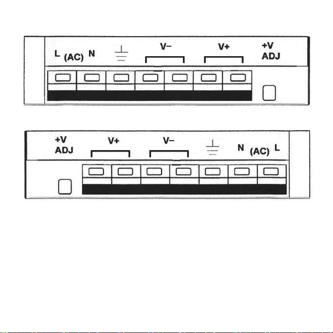
•Connect to the mains supply ensuring the correct polarity is observed (see Fig. 1): L –Live (brown),
E –Earth (green/yellow), N –Neutral (blue)
Fig. 1
•Switch on and check for correct operation
This driver is equipped with an output voltage adjuster (+V ADJ) which can increase or decrease the output
voltage by approximately 10%. No adjustment should be necessary, but should the driver be loaded to its total
capacity the voltage can be trimmed to help prevent overload; alternatively increasing the output voltage can
help to compensate for voltage drop on the load side.
WARNING
This product must be disconnected from the circuit if subjected to any high voltage or insulation resistance
testing. Irreparable damage will occur if this instruction is not followed.
GENERAL
INSTALLATION & MAINTENANCE MANUAL
These instructions should be read carefully and retained after installation by the end user for future reference
and maintenance.
These instructions should be used to aid installation of the following products:
24DC100M / 24DC150M / 24DC200M
SAFETY
•This product must be installed in accordance with the latest edition of the IEE Wiring Regulations
(BS7671) and current Building Regulations. If in any doubt, consult a qualified electrician
•Please isolate mains prior to installation or maintenance
•Check the total load on the circuit (including when this product is fitted) does not exceed the rating of
the circuit cable, fuse, or circuit breaker
•Please note the IP (Ingress Protection) rating of this product when deciding the location for installation
•Allow 50mm above and around the fitting for air dissipation (do not cover the fitting with insulation)
•Do not overload this accessory or subject it to conditions outside its rating
•This product is for indoor use only
•This product must be placed inside a suitable enclosure
•This product is Class I and must be earthed
•This product is IP20 rated (IP20 from above)
INSTALLATION
•Provide power to the required point of installation
•Mount the driver in a suitable vented enclosure ensuring there is adequate space around and above
the product for heat dissipation
•Connect to the mains supply ensuring the correct polarity is observed (see Fig. 1): L –Live (brown),
E –Earth (green/yellow), N –Neutral (blue)
Fig. 1
•Switch on and check for correct operation
This driver is equipped with an output voltage adjuster (+V ADJ) which can increase or decrease the output
voltage by approximately 10%. No adjustment should be necessary, but should the driver be loaded to its total
capacity the voltage can be trimmed to help prevent overload; alternatively increasing the output voltage can
help to compensate for voltage drop on the load side.
WARNING
This product must be disconnected from the circuit if subjected to any high voltage or insulation resistance
testing. Irreparable damage will occur if this instruction is not followed.
GENERAL
24DC100M / 24DC150M
24DC200M
Fig.1