MM Kembla KemPress KPSA2 User manual

COPPER
PRESS-FIT
FITTINGS FOR
FOR USE WITH
EUROPEAN
PLUMBING TUBE
BSEN 1057
DESIGN &
INSTALLATION
GUIDE
®

A NEW GENERATION OF COPPER
PRESS-FITTINGS OFFERING ALL THE
BENEFITS OF COPPER AND NOW EVEN
EASIER TO INSTALL.
MM Kembla has combined the experience and knowledge
of over 100 years of Australian copper tube manufacturing
with press-t technology and German engineering to
produce the KemPress® copper press-t connection
system. With a warranty of 25 years, and a design life of
over 50 years, KemPress®offers you peace of mind and
the simplicity that you want.
MM Kembla has been supplying high quality copper tube
into Hong Kong for over 20 years. Kembla has combined
the technical knowledge and local know how to deliver
KemPress®via Kembla Hong Kong.
When you need the highest quality press-t system,
use Kembla copper tube, KemPress® ttings and the
KemPress®tool. Our tools are of the highest quality,
are the lightest on the market and have the longest
service life.
To make life easy for plumbers the KemPress®system
is compatible with EN1057 copper tube.*
WHY USE KEMPRESS®?
• Complete plumbing system with one warranty
- Kembla copper tube
- Kembla KemPress® ttings
- Kembla KemPress®tool
• Fast to install
- Faster than conventional brazing
- Reduced labour costs
• Easy to use
- No need to drain water out of the system
- No brazing skills required
• Flame free connection
- No hot works permit required
• High quality ttings
- Manufactured to stringent standards and
quality controls
• Push and Stay
- Fitting is tight enough to complete the rough
in before securing placement by pressing
• High quality, lightweight KemPress®tool
- Slim lightweight and ergonomic design
- One hand operation. Once the jaws are inserted
the weight is balanced
- Smart electronic controls and Bluetooth connectivity
for performance job monitoring using the NovoCheck
App (KPSA2 & KPL3).
- Press area illumination (KPSA2 & KPL3) and Brushless
Motor Technology for more presses per battery
charge (KPL3)
- Longest interval between servicing
- KPSA2 40,000 presses
- KPL3 & KPXL2 unlimited for 2 years
- Second battery included
• Backed by Kembla Hong Kong’s reputation for
high quality products, service and customer care
2
®
* See brochure Kembla Copper tube
to European standard to BS EN 1057

TECHNICAL SPECIFICATIONS
Copper tube
MM Kembla recommends using our high quality Australian
made Kembla copper tube. KemPress®is suitable for
use with hard and half hard Table X & Y copper tube
complying with EN1057 unless noted otherwise in the
installation guidelines.
The tube must be in reasonable condition with no signs
of external corrosion or any surface damage.
For detailed information on copper tube specications
refer to The Plumbers Handbook. Contact Kembla Hong
Kong to obtain a hard copy or download the latest edition
from our website: www.kembla.com.au
Fittings
KemPress® ttings have been manufactured and quality
controlled in accordance with strict MM Kembla quality
controls.
Inside each tting is an Elastomeric O-ring. See the
O-ring compatibility table for specic applications.
It is essential that the O-rings are not contaminated
or damaged by foreign material such as copper swarf
or sharp metal.
Push and Stay Feature
The KemPress® ttings have been designed to provide
a tight t when pushed together to allow the rough in
to be completed prior to pressing. This ensures you have
the right design and tube placement and allows you to
make adjustments, if required, prior to pressing. This is
especially benecial for vertical installations.
Note: Due to movement it is important to check that you
have full engagement of your ttings on the tube prior to
pressing. Use the mark made in step 4 of the installation
process (See page 8) as your guide.
Press prole
The KemPress® ttings are designed to deliver minimal
deformation to the internal shape of the tube they are
connecting to, reducing turbulence in the ow of the uid.
The connection provides a rigid coupling with excellent
resistance to torsional forces. This is particularly benecial
when connecting mechanical threaded connections.
Pressing Process
The objective of the pressing process is to deliver a
permanent connection while achieving the required pull
out strength according to WRAS. The KemPress®process
presses the lip of the tting and then compresses the
O-ring at the same time.
Stability Level
Compression of press tting
and supporting tube
Tightening Level
Compression of
the sealing ring
3
®

UNPRESSED FITTINGS
Once pressed the KemPress® ttings will not leak.
It is important to check every tting has been pressed.
The KemPress®system has been designed to make it
very obvious to detect an unpressed tting prior to the
commissioning of the system. To assist in identifying
unpressed ttings, the KemPress system has also been
designed with a Leak Path feature that will cause the
tting to leak during low pressure leak path testing if
it has not been pressed.
Visual Inspection
Pressed and unpressed ttings are clearly distinguished
on a visual inspection. To assist in identifying unpressed
ttings, the KemPress system has also been designed with
a Leak Path feature that will cause the tting to leak during
low pressure leak path testing if it has not been pressed.
KEMPRESS LEAK PATH TESTING –
IDENTIFYING AN UNPRESSED FITTING
When un-pressed, all KemPress ttings are designed with
a feature that will allow a small amount of water, or gas, to
escape from the un-pressed joint. This is known as a ‘Leak
Path’. This feature may take the form of either a specially
engineered section of the sealing ring, or tolerances within
the tting itself. It is recommended a ‘Leak Path’ test is carried
out where possible with air, to minimise any inconvenience
caused by leaking joints, and delay the introduction of water
or uids until the system is ready for commissioning.
The ‘Leak Path’ is designed to work at low pressures, i.e.
at 100KPa or less. At higher pressures, the force of the
water or air/gas may compress the sealing ring against the
tting and inadvertently seal the ‘Leak Path’. This is why
the ‘Leak Path’ test must be carried out at a maximum of
15KPa for air/gas or 100KPa for water.
Testing of the KemPress system should comprise of two
parts: Firstly, a low pressure test, which will allow any
un-pressed ttings to be identied by the ‘Leak Path’
feature, and the second part of the test at a higher
pressure to act as a ‘Tightness Test’.
LEAK PATH TESTING WITH WATER
When lling a system, constant checks should be made
for early signs of the ‘Leak Path’ identifying an un-pressed
tting. Ideally, pressure testing should be done with
water that is as close to ambient temperature as possible.
Using water that is heated can cause a false pressure
drop reading if allowed to cool over an extended
‘Tightness Test’ period. It is recommended a 30 minute
settling period is allowed for to allow any temperature
variances to equalise. Once lled, care should also be
taken to ensure that all water and air is removed from
the system.
Step 1 – Leak Path Test:
• Once the system has settled, the ‘Leak Path’ test should
be carried out at 100KPa, for a period of 10 minutes.
During this time, we recommend a visual inspection of
all joints and connections, and this inspection should
be recorded on our ‘Pressure Test Log’. If a tting
has been left un-pressed, then the un-pressed tting
should be visible as a bead of water coming from the
un-pressed joint.
• If an un-pressed tting is detected, the pressure should
be released from the system before the tting is pressed.
Please also ensure that the pipe is still inserted to the
correct depth before pressing. Once the press has been
completed, the test should be repeated.
Step 2 – Tightness Test:
•
Once the ‘Leak Path’ test is complete, then the mechanical
strength test can begin. Testing a drinking water system
should be done at 1.1 times the Maximum Operating
Pressure (MOP), and with a heating or chilled system
at 1.3 times the Maximum Operating Pressure (MOP).
• If high operating pressures are required, we would
suggest that the pressure is built up in stages. For
example, raised to 500KPa for 10 minutes, then raised
to 1000KPa for 10 minutes and nally to 1600KPa
(maximum pressure capability). This is not mandatory,
but if a tting has been pressed but is incorrectly
installed, and it fails, it is better that it fails at a lower
pressure.
LEAK PATH TESTING WITH AIR/GAS
When testing with air/gas, at pressures higher than 100KPa
due care and attention must be taken when considering
the potential health/safety hazards to workers in the
vicinity. Air/gas, when compressed to high pressures, can
store signicant energy. In the event of a joint failure due
to a tting being incorrectly installed, this energy, which if
released suddenly, can have an explosive-like effect.
Unpressed tting - smooth with
no indents.
Pressed tting - indents on the
tting.
Unpressed tting - small gap
between tting and tube.
Pressed tting - no gap
between tting and tube.
4
®

Always ensure the temperature of the testing air or gas,
which must be oil free, and the ambient temperature are
as close as possible. It is advisable to allow a settling
down period of approximately one hour depending on
the volume of the system.
Step 1 – Leak Path Test:
• The initial air test is a ‘Leak Path’ test and should be
performed at 15 KPa for a minimum of 120 minutes,
for a system with a volume up to 100 litres. An extra
20 minutes of testing time should be added for every
additional 100 litres of system volume.
•
No pressure drop is to be permitted during this test period.
Step 2 – Tightness Test:
• Once the ‘Leak Path’ test has been completed and
passed, a mechanical strength test can commence.
A maximum pressure of 300KPa, for a period of 10
minutes is recommended. We also suggest the pressure
is elevated in steps of 100KPa per 10 minutes. Again, no
pressure drop is allowed during this period. If higher
test pressures are required, pressures are to be
elevated in steps of one bar every 10 minutes.
•
The maximum operating pressure for a system carrying air
or technical gas is 1600KPa. A system intended to carry fuel
gas is rated at a maximum operating pressure of 500KPa.
•
If during any testing a pressure drop is detected, then the
testing process should be halted, and the location of the
leak identied and remedied. A report should be made
and kept of the initial failed test. Once the fault has been
corrected, the whole pressure test process should be
re-commenced from the beginning.
TESTING & COMMISSIONING
When water tting installations are complete, it is essential
to ush with water before use to remove dust, debris and
ux residues, in accordance with the relevant plumbing
installation code.
Drinking water installations should be tested and
inspected in accordance with the code for leaks and
remedial action taken if necessary.
KemPress® ttings maintain earth continuity without
the need for additional continuity straps.
CERTIFICATION & TESTING
KemPress® has achieved WRAS certication and the
Australian watermark certication. The ttings have
undergone a rigorous testing program including:
• Prototype testing
- burst pressure
• Watermark testing
- Water tightness
- Strength of fabrication
- Strength of joint assembly
- Pull-out strength
- Thermal cycling
• Material in contact with drinking water
• Press testing every product in the range
• Press testing every tool and Jaw
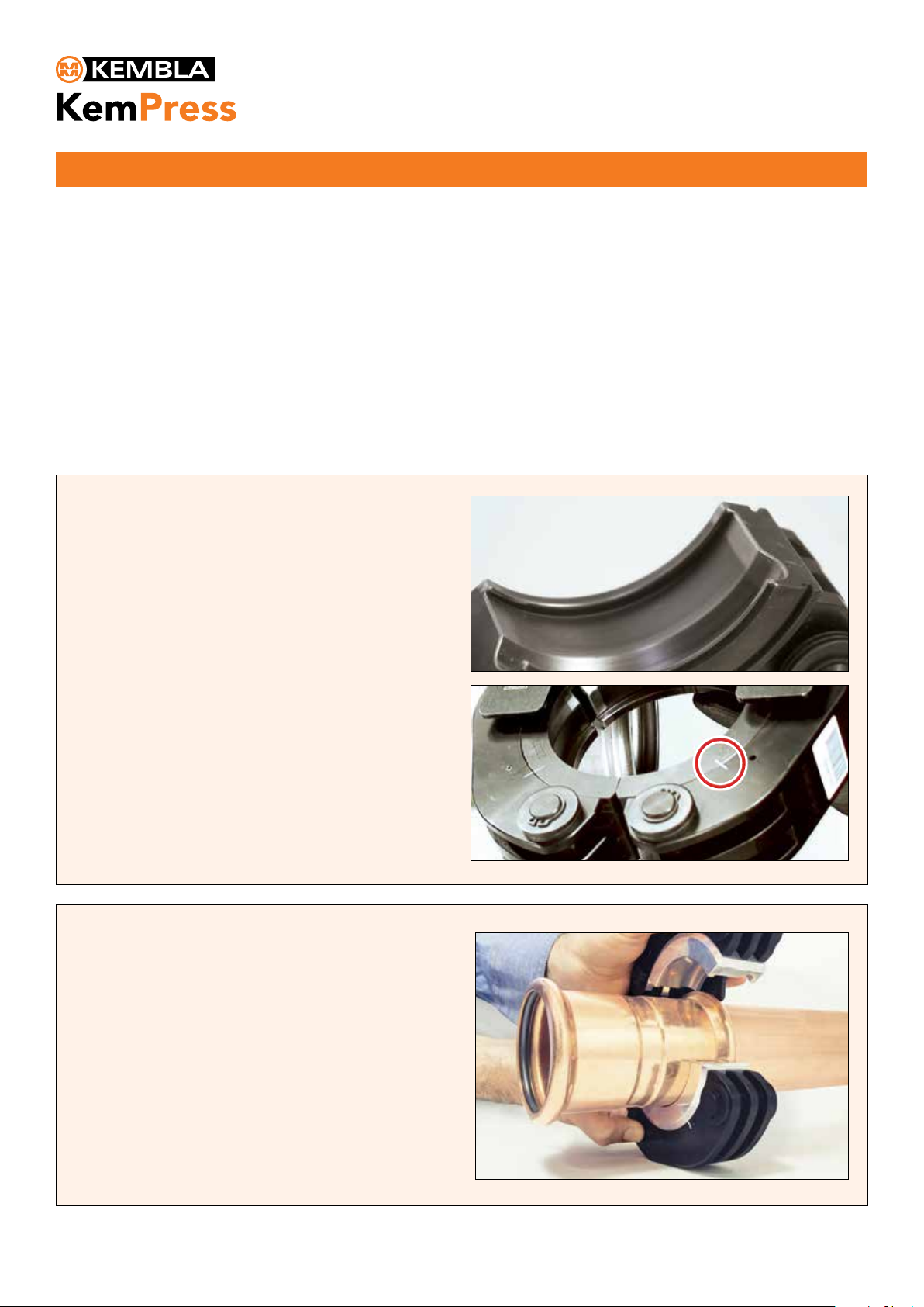
O-RING
The O-ring is pre-lubricated and should be protected
from contamination by foreign objects to avoid
damaging the integrity of the product (for example
copper lings when cutting copper tubes).
Water applications use an EPDM (Ethylene Propylene
Diene Monomer) O-ring. This O-ring is suitable for
standard water applications designated below.
For hot water temperatures exceeding 120oC please
contact Kembla Hong Kong for guidance.
The pre-lubricated O-ring has passed the materials
on contact with drinking water certication in Australia
and through WRAS.
WATER FITTINGS
Application Pressure Temperature
KPa oC
Hot & Cold Potable Water 1600 120
Chilled water 1600 -25
Rainwater installations 1600 Ambient
Vacuum - 80 Ambient
Domestic re sprinkler systems 1600 Ambient
Compressed air installations (oil free) 1600 70
5
®
Page 1of 34
Australian Certification Services P ty Ltd ABN 37 121 022 366
POBox 627 Jannali, NSW 2226 AUSTRALIA
www.certificationservices.com.au
www.jas-anz.org/register
Certificate Number: 23087
IssueDate: 22nd May 2017
Issue:02 Revision: 02
Level 1
Certificate of Conformity
Australian Certification Services Pty Ltd grants to the WaterMark User:
Metal Manufactures Ltd
Trading as MM Kembla
the right to use the WaterMark as shown above in conjunction with the Certificate No. on product/s as identified in the
WaterMark Schedule and as listed on the WaterMark database www.abcb.gov.au/ Product-Certification/WaterMark-
Certification-Scheme which have been shown to comply with the relevant Standard/s and level of certi fication referred
to below. The WaterMark User is granted a licence to use the WaterMark subject to the rules governing the use of the
WaterMark.
Product Type:
Metallic Press Fit Fittings
Brand:
KemPress® Copper KemPress® Stainless
Evaluated to:
AS 3688:2005 Amdt 1 2006 Water supply—Metallicfittings and end connectors
AS 3688:2016 Water supply and gas systems
—Metallic fittings and end
connectors
Issue Date
15th September 2017
Paul Greig
Initial Issue Date:
8th December 2011
General Manager
Expiry Date:
7th December 2021
Certificate No.: 23087
This certificate remains the property of Australian Certification Servic es Pty Ltd
WaterMark Level 1 certification is a conformity assessment scheme based on ISO Guide 67 (system 5)
Certificate No.
Secretary
This certifies that
has had the undermentioned product examined, tested and found,
when correctly installed, to comply with the requirements of the
United Kingdom Water Supply (Water Fittings) Regulations and
Scottish Water Byelaws.
The certificate by itself is not evidence of a valid WRAS Approval. Confirmation ofthe current
status of an approval must be obtained from the WRAS Directory (www.wras.co.uk/directory)
The product so mentioned will be valid until the end of:
Chairman, Product Assessment Group
June2017
MM KEMBLA
KEMPRESS RANGE OF PRESS-FIT TRANSITION FITTINGS
January 2024
1901708
Certificate No.
Secretary
This certifies that
has had the undermentioned product examined, tested and found,
when correctly installed, to comply with the requirements of the
United Kingdom Water Supply (Water Fittings) Regulations and
Scottish Water Byelaws.
The certificate by itself is not evidence of a valid WRAS Approval. Confirmation ofthe current
status of an approval must be obtained from the WRAS Directory (www.wras.co.uk/directory)
The product so mentioned will be valid until the end of:
Chairman, Product Assessment Group
June2017
MM KEMBLA
KEMPRESS COPPER PRESS-FIT FITTINGS
January 2024
1901707

6
®
* Available
on request
COPPER Customer Customer/ Pack Carton
FITTINGS Dimension Article No. Qty Qty
(mm
Connector 15 J07023 10 500
Female/Female 22 J07024 10 200
28 J07025 5 125
35 J07026 2 80
42 J07027 2 40
54 J07028 2 32
67 J07210 1 14
76 J07211 1 10
108 J07212 1 4
* Connector Slip 15 J07029 10 300
22 J07030 10 150
28 J07031 5 100
35 J07032 2 50
42 J07033 2 40
54 J07034 2 24
67 J07224 1 15
76 J07225 1 10
Tee - Equal 15 J07035 10 200
Female/Female 22 J07036 10 80
/Female 28 J07037 5 60
35 J07038 2 30
42 J07039 2 22
54 J07040 2 12
67 J07206 1 6
76 J07186 1 3
108 J07203 1 1
Tee - Reducing EndxBranchxEnd
Female/Female 22x15x15 J07041 10 150
/Female 22x15x22 J07042 10 120
22x22x15 J07043 10 100
28x15x28 J07044 5 80
28x22x28 J07045 5 60
35x15x35 J07046 2 50
35x22x35 J07047 2 50
35x28x35 J07048 2 36
42x22x42 J07049 2 30
42x28x42 J07050 2 26
42x35x42 J07051 2 24
54x22x54 J07052 2 18
54x28x54 J07053 2 14
54x35x54 J07054 2 14
54x42x54 J07055 2 14
67x28x67 J07207 1 10
67x35x67 J07190 1 10
67x42x67 J07208 1 8
67x54x67 J07191 1 6
76x22x76 J07192 1 8
76x28x76 J07193 1 6
76x35x76 J07209 1 6
76x42x76 J07194 1 6
76x54x76 J07213 1 6
76x67x76 J07195 1 6
108x54x108 J07196 1 2
108x67x108 J07205 1 2
108x76x108 J07197 1 2
COPPER Customer Customer/ Pack Carton
FITTINGS Dimension Article No. Qty Qty
(mm)
900Elbow 15 J07000 10 350
Female/Female 22 J07001 10 130
28 J07002 5 75
35 J07003 2 40
42 J07004 2 24
54 J07005 2 12
67 J07180 1 6
76 J07181 1 4
108 J07182 1 1
900Elbow* 15 J07006 10 350
Male/Female 22 J07007 10 130
28 J07008 5 75
35 J07009 2 40
42 J07010 2 22
54 J07011 2 12
450Elbow 15 J07012 10 350
Female/Female 22 J07013 10 160
28 J07014 5 100
35 J07015 2 50
42 J07016 2 30
54 J07017 2 18
67 J07201 1 12
76 J07202 1 6
108 J07237 1 2
450Elbow* 15 J06998 10 400
Male/Female 22 J06999 10 180
28 J07018 5 100
35 J07019 2 50
42 J07020 2 30
54 J07022 2 18
Bushing 22x15 J07068 10 350
Male/Female 28x15 J07069 5 200
28x22 J07070 5 150
35x22 J07071 2 100
35x28 J07072 2 100
42x22 J07073 2 70
42x28 J07074 2 70
42x35 J07131 2 60
54x35 J07075 2 40
54x42 J07076 2 36
67x28 J07103 1 20
67x35 J07220 1 20
67x42 J07221 1 18
67x54 J07200 1 16
76x35 J07104 1 20
76x42 J07105 1 18
76x54 J07222 1 12
76x67 J07223 1 15
108x42 J07215 1 4
108x54 J07216 1 4
108x67 J07218 1 4
108x76 J07219 1 4
PRODUCT RANGE

7
®
PRODUCT RANGE
COPPER Customer Customer/ Pack Carton
FITTINGS Dimension Article No. Qty Qty
(mm)
Reducer 22x15 J07057 10 250
Female/Female 22x18 J07058 10 250
28x15 J07059 5 160
28x22 J07158 5 125
35x22 J07060 2 10
35x28 J07061 2 80
42x22 J07062 2 70
42x28 J07063 2 60
42x35 J07064 2 44
54x28 J07065 2 40
54x35 J07066 2 40
54x42 J07067 2 30
End Cap 15 J07239 10 800
22 J07240 10 300
28 J07241 5 250
35 J07242 2 120
42 J07243 2 90
54 J07244 2 40
67 J07226 1 30
76 J07227 1 20
108 J07228 1 10
Female Tee 22x1/2” J07132 10 60
28x1/2” J07077 5 40
28x3/4” J07078 5 40
35x1/2” J07079 2 30
42x1/2” J07080 2 18
Male Coupling 15x1/2” J07081 10 300
15x3/4” J07082 10 200
22x1/2” J07083 10 150
22x3/4” J07084 10 120
28x3/4” J07085 5 100
28x1” J07086 5 100
35x1-1/4” J07087 2 50
42x1-1/2” J07088 2 40
54x2” J07089 2 16
67x2-1/2” J07229 1 10
76x3” J07230 1 5
108x4” J07231 1 2
Female Coupling 15x1/2” J07090 10 250
15x3/4” J07091 10 150
22x1/2” J07092 10 150
22x3/4” J07093 10 120
28x3/4” J07094 5 100
28x1” J07095 5 80
35x1-1/4” J07096 2 40
42x1-1/2” J07097 2 30
54x2” J07098 2 20
67x2-1/2” J07232 1 10
76x2-1/2” J07238 1 5
COPPER Customer Customer/ Pack Carton
FITTINGS Dimension Article No. Qty Qty
(mm)
Wallplate Elbow 15x1/2” J07099 10 100
22x3/4” J07100 10 60
Union Adaptor 15x3/4” J07144 5 120
Flat Seal 22x3/4” J07101 5 60
76x3” J07233 1 10
900Elbow 15x1/2” J07133 10 150
Female Couplng 15x3/4” J07134 10 100
22x1/2” J07135 10 100
22x3/4” J07136 10 80
22x1” J07137 10 40
28x1/2” J07138 5 80
28x3/4” J07139 5 50
28x1” J07140 5 30
35x1-1/4” J07141 2 20
42x1-1/2” J07142 2 12
54x2” J07143 2 6
900Elbow 15x1/2” J07149 10 200
Male Couplng 15x3/4” J07150 10 150
22x1/2” J07151 10 100
22x3/4” J07152 10 80
22x1” J07153 10 50
28x1” J07154 5 50
35x1-1/4” J07155 2 30
42x1-1/2” J07156 2 12
54x2” J07157 2 10
Flange PN16 28 J07145 1 6
35 J07146 1 4
42 J07147 1 3
54 J07148 1 2
67 J07234 1 4
76 J07235 1 3
108 J07236 1 2

8
2. Deburr carefully the end of the tube on the inside to
minimize turbulence and pressure loss according to the
relevant plumbing code and on the outside to avoid
damaging the O-ring.
The following is a step by step guide to installing the KemPress®System for EN sizes 15mm - 35mm. For projects requiring
maintenance and repair, visually inspect the copper tube to ensure it is in reasonable condition with no signs of external corrosion
or scores. Installation shall be in accordance with relevant installation standards and the KemPress® Design & Installation Guide.
Failure to adhere to either can result in the warranty being voided.
3. For existing copper tube, clean the end with emery
paper or a soft scourer.
4. Mark the insertion depth by lining up the tting side by
side with the tube and mark the tube. When the tting is
inserted onto the tube the outer edge of the tting must
line up with the marking. For correct insertion depths see
the table below.
1. Cut copper tube to length using a pipe cutter.
5. Select pressing jaw according to the tting dimension and
insert into the pressing machine. Arrest the locking bolts of
the machine. Check the jaws are free from debris and in
good working order.
®
15MM - 35MM INSTALLATION GUIDELINES
Tube Size Insertion Depth
mm mm
15 20
22 24
28 27
35 32
42 38
54 43
66.7 47
76.1 50
108 69

7. Check the tting outer edge still lines up with the marking.
Open the pressing jaw and close it around the tting so
the raised bump in the tting rests inside the groove of the
pressing jaw.
8. Initiate the pressing job by pressing the start button.
The automatic pressing process creates a tight connection.
6. Check the tting is clean and the O-ring is free from debris
and correctly sitting in place. Push tting on tube all the
way to the engagement marking.
9. Visually inspect the tting to ensure the press has been
completed. The KemPress® tool will ash if the tting did
not press correctly. If this occurs a new tting and tube
section is required. At the end of the project visually inspect
each tting to ensure none have been missed.
9
CAUTION
MINIMUM DISTANCE FOR BRAZING NEAR A KEMPRESS®FITTING
Tube Size (mm) 15 22 28 35 42 54 67 76 108
Minimum clearance to existing connection (mm) 350 550 730 875 1000 1400 1700 2000 2300
Minimum clearance to existing brazed tting (mm) 10 10 10 10 20 20 20 20 20
®
15MM - 35MM INSTALLATION GUIDELINES
Brazing or soldering near to KemPress
®
joints should be avoided as this may cause the seal to degrade due to heat transfer.
The table below states the minimum distance away from the press joint which is acceptable to braze. If this distance cannot
be maintained then adequate precautions must be taken such as fabricating the brazed section prior to assembly with the press ttings,
wrapping the press joint in a wet rag and keeping cool during brazing or applying tube freezing spray.

10
The following is a step by step guide to installing the
KemPress®System for EN sizes 42mm - 54mm. For projects
requiring maintenance and repair, visually inspect the copper
tube to ensure it is in reasonable condition with no signs of
external corrosion or scores. Installation shall be in accordance
with relevant installation standards and the KemPress®Design
& Installation Guide. Failure to adhere to either can result in
the warranty being voided.
For the dimensions 42 and 54mm, the use of the KPL, KPL2,
KPL3, KPXL, KPXL2 or other approved press tool is required.
KemPress®tools require adaptor jaw ZB203 and 42 and
54mm collars for these sizes.
Prior to the following installation steps, complete st eps 1- 4
as per the 15-35mm installations instructions on page 8.
®
42MM - 54MM INSTALLATION GUIDELINES
STEP 6
Place the collar around the KemPress® tting such that the
bead of the tting is inserted into the groove of the press
collar. Close press collar. Make certain that the press collar
ts tightly into the tting. Afterwards position the pressing
collar by rotating it so that the pressing machine can be
correctly attached.
STEP 5
Select the appropriate press collar and check that it is
clean and that the surface is smooth. In order to ensure
correct operation of the press collars, the sliding segments
must be free to move/slide. The sliding segments are
tensioned by springs, holding them in the correct starting
position. Please ensure that the marking lines on the
inner and outer rings form a line for the correct starting
position. If the segments are not freely moving, clean and
lubricate with light machine oil or have them serviced by
an approved KemPress®service agent.

11
®
42MM - 54MM INSTALLATION GUIDELINES
STEP 8
Open the adaptor jaw by depressing the jaw levers and
attach to the press collar so that the claws of the adaptor
jaw grip around the pins of the press collar. Check whether
ttings outer edge lines up with the marker of the insertion
depth then start the pressing procedure by pressing
the start button. The pressing procedure should not be
interrupted prematurely. Following this procedure ensures
a permanently sealed connection always results. For safety,
the pressing process can be stopped by pressing the
emergency stop button. Once the emergency button has
been activated, the tool will need to be reset. The affected
tting and tube section should be discarded and new
components used.
STEP 9
Loosen the press collar by pulling apart.
STEP 7
Select adaptor jaw ZB203 for the
dimensions 42 mm and 54 mm.
Insert the adaptor jaw into the press
tool and close the locking bolts.

The following is a step by step guide to installing the
KemPress® System for EN sizes 66.7mm and 76.1mm.
For projects requiring maintenance and repair, visually inspect
the copper tube to ensure it is in reasonable condition with
no signs of external corrosion or scores. Installation shall be
in accordance with relevant installation standards and the
KemPress® Design & Installation Guide. Failure to adhere to
either can result in the warranty being voided.
For the dimensions 66.7mm and 76.1mm, the use of the KPXL/
KPXL2 or other approved press tool is required. KemPress®
tools require adaptor jaw ZB221 and 66.7mm, 76.1mm collars
for these sizes.
Prior to the following installation steps, complete steps 1-4
as per the 15-35mm installations instructions on page 8.
®
66.7MM - 76.1MM INSTALLATION GUIDELINES
STEP 6
Place the collar around the KemPress® tting such that the
bead of the tting is inserted into the groove of the press
collar. Close press collar. Make certain that the press collar
ts tightly into the tting. Afterwards position the pressing
collar by rotating it so that the pressing machine can be
correctly attached.
STEP 5
Select the appropriate press collar and check that it is clean
and that the surface is smooth. In order to ensure correct
operation of the press collars, the sliding segments must
be free to move/slide. The sliding segments are tensioned
by springs, holding them in the correct starting position.
Please ensure that the marking lines on the inner and outer
rings form a line for the correct starting position. If the
segments are not freely moving, clean and lubricate with
light machine oil or have them serviced by an approved
KemPress®service agent.
12

®
66.7MM - 76.1MM INSTALLATION GUIDELINES
STEP 8
Open the adaptor jaw by depressing the jaw levers and
attach to the press collar so that the claws of the adaptor
jaw grip around the pins of the press collar. Check whether
ttings outer edge lines up with the marker of the insertion
depth then start the pressing procedure by pressing
the start button. The pressing procedure should not be
interrupted prematurely. Following this procedure ensures
a permanently sealed connection always results. For safety,
the pressing process can be stopped by pressing the
emergency stop button. Once the emergency button has
been activated, the tool will need to be reset. The affected
tting and tube section should be discarded and new
components used.
STEP 9
Loosen the press collar by pulling apart.
STEP 7
Select adaptor jaw ZB221 for the
dimensions 66.7 mm 76.1 mm.
Insert the adaptor jaw into the
press tool and close the locking
bolts.
13

The following is a step by step guide to installing the
KemPress®System for EN size 108mm. For projects requiring
maintenance and repair, visually inspect the copper tube to
ensure it is in reasonable condition with no signs of external
corrosion or scores. Installation shall be in accordance with
relevant installation standards and the KemPress®Design
& Installation Guide. Failure to adhere to either can result in
the warranty being voided.
For the dimension 108mm, the use of the KPXL/KPXL2 or
other approved press tool is required. KemPress® tools require
adaptor jaw ZB221 (for the 1st press), adaptor jaw ZB222 (for
the 2nd press) and the 108mm collar.
Prior to the following installation steps, complete steps 1-4
as per the 15-35mm installations instructions on page 8.
Note the 108mm installation requires 2 presses, the rst press
with the ZB221 adaptor jaw and the second press with the
ZB222 adaptor jaw.
®
108MM INSTALLATION GUIDELINES
STEP 6
Place the collar around the KemPress® tting such that
the bead of the tting is inserted into the slot of the press
collar. Close press collar and secure the fastening latch.
Make certain that the press collar ts tightly into the tting.
Afterwards position the pressing collar by rotating it so that
the pressing machine can be correctly attached.
STEP 5
Select the 108mm press collar and check that it is clean
and that the surface is smooth. In order to ensure correct
operation of the press collar, the sliding segments must
be free to move/slide. The sliding segments are tensioned
by springs, holding them in the correct starting position.
Please ensure that the marking lines on the inner and outer
rings form a line for the correct starting position. If the
segments are not freely moving, clean and lubricate with
light machine oil or have them serviced by an approved
KemPress®service agent.
14

®
108MM INSTALLATION GUIDELINES
STEP 8
Open the adaptor jaw by depressing the jaw levers and
attach to the press collar so that the claws of the adaptor
jaw grip around the pins of the press collar. Check whether
ttings outer edge lines up with the marker of the insertion
depth then start the pressing procedure by pressing the start
button. The pressing procedure should not be interrupted
prematurely. Following this procedure ensures
a permanently sealed connection always results. After
completing the pressing process, the pressing tool can be
removed from the press collar by opening the intermediate
jaw. Then carry out step 7 to 9 using the intermediate jaw
ZB222 to complete the second stage of pressing in order
to close the press collar completely. For safety, the pressing
process can be stopped by pressing the emergency stop
button. Once the emergency button has been activated,
the tool will need to be reset. The affected tting and tube
section should be discarded and new components used.
NOTE: Step 8 requires the use of the ZB221 and ZB222
adaptor jaws. The process requires two presses in total.
STEP 7
Select adaptor jaw ZB221 for the
108mm dimensions rst press.
Insert the adaptor jaw into the
press tool and close the locking
bolts.
STEP 9
Loosen the press collar by releasing the fastening latch and
then pull apart.
15

PRESS TOOL
The KemPress®tool is the smartest, lightweight copper
pressing tool on the market and its slim line design
makes it easy to handle. It has been specically
designed and tested to work with KemPress® ttings.
There is a small tool and a large tool which deliver
different pressing forces. The jaws have been designed
specically for each tool and are not interchangeable.
• Lightest tools on the market
• One hand operation (Patent)
• Perfectly balanced with Jaws
• Longest Maintenance interval
- KPXL2 - Unlimited, service every 2 years
- KPL3 - Unlimited, service every 2 years
- KPSA2 - 40,000 pressing cycles
• Smart electronic controls: Flashes if not
pressed correctly Battery status indicator
• Bluetooth connectivity for tool and job performance
monitoring using the NovoCheck App (KPSA2 &
KPL3) and any smart phone or tablet
• Second battery included, rapid recharge (30 mins)
• Tool Service Program: Service centre operated by
Kembla Hong Kong Loan tool provided during
service/repair
Small tool (KPSA2) designed for 15, 22, 28, and 35mm
Large tool (KPL3) designed for 15, 22, 28, 35, 42 and
54mm
Extra Large tool KPXL/KPXL2 designed for 15, 22, 28,
35, 42, 54, 66.7, 76.1 and 108mm
16
®
TECHNICAL DATA Small Tool Large Tool Extra Large Tool
(KPSA2) (KPL3) (KPXL2)
Dimensions 15mm to 35mm 15mm to 54mm 15mm to 108mm
Weight incl. Battery 1.7 kg 2.8 kg 3.9 kg
Length 320 mm 387 mm 480 mm
Width 98 mm 75 mm 83 mm
Height 72 mm 111 mm 113 mm
Power consumption 240 W 450 W 450 W
Piston Force 21 kN 32 kN 32 kN
(minimum press
force)
Piston stroke 30 mm 40 mm 80 mm
Battery 12V/1.5 Ah Li-Ion 18V/1.5 Ah Li-Ion 18V/3.0 Ah Li-Ion
Charging time 30 min 30 min 60 min
Number of presses 40,000 cycles Unlimited, service Unlimited, service
before service every 2 years every 2 years every 2 years
KEMPRESS EN COPPER TOOLING SPECIFICATIONS
Tool OD Size Presses per
(mm) battery life
KPSA2 15 129
22 116
28 105
35 104
KPL3 15 86
22 85
28 82
35 81
42 65
54 54
KPXL2 15 242
22 239
28 231
35 228
42 185
54 129
67 57
76 59
108 21
PRESSING CYCLES

Key Features
• Safe handling with slip-proof rubberised housing
• Signals if press not completed correctly
-
Immediately
after the pressing cycle a green lights shows if the
required pressing force was achieved, a red light if not
• Automatic press cycle. Once it starts, it will
automatically complete. (manual override)
• Electronic log book allows for quick and precise
analysis of errors for servicing and repair
• Electronic monitoring of the jaw locking
bolt and visual error indicator (KPL)
• When you reach the maximum number of presses
before a service is required a warning light ashes.
The machine will not close down enabling you to
complete the job in hand.
• Redundant switch-off
Tool Operation
Holding the tool securely, press and hold the start button
for 2 seconds to begin the automatic press cycle (the green
LED will go out). Release the start button and continue to
hold the tool securely. The green LED will light when the
press cycle is complete. To cancel the automatic press cycle
press and hold the release button on the side of the tool
until the tool turns off.
If the red LED lights up, press the start button. If the tool
does not run, contact Kembla Hong Kong for advice. If the
red and green LEDs ash alternately, the tool is ready for
a service, contact Kembla Hong Kong Customer Service
Centre.
The tool will turn off automatically after 30 minutes of no use.
Turn the tool ON by quickly pressing and releasing the start
button and open the jaws around the tting.
Bluetooth Connectivity & NovoCheck (KPSA2 & KPL3)
New KPSA2 and KPL3 tools are equipped with Bluetooth
technology so you can connect to you press tool straight
from your smart phone or tablet using the intelligent
NovoCheck App. The NovoCheck App allows you to
monitor the performance of your tool and installation
with the following unique features:
•
Pre-start tool checks to ensure your tool is ready for work
• Analysis of your tools performance, usage and time until
next service
• Ability to change your tool settings
• Generate installations reports that showing completed
and incomplete press information
• Compare completed press results to the number of presses
required for a section of work to ensure the job has been
completed with all ttings pressed in your installation
To begin monitoring your tool and installation performance,
simply download the NovoCheck App onto your smart phone
or tablet via the Apple App Store or Google Play.
Tool Maintenance
Carry out basic inspection of the pressing device and jaws
prior to each use to ensure they are clean and free from
debris and dirt. The pressing jaws should be visually inspected
to ensure there are no cracks. If there are any cracks in the
pressing jaws, do not use them, as there is risk of the jaws
shattering and potential injury from ying fragments. It is
recommended to always wear appropriate eye protection
whenever using the pressing device. When inspecting the
pressing jaws, also ensure that there are no foreign material
deposits and that the contours of the jaw surfaces are in order.
Failure to do this may result in damage to the jaws and/or the
pressing device. Always remove the battery before performing
regular cleaning and maintenance work.
Regular application of light machine oil to the moving parts of
the jaws, adaptor jaws and collars and general application of
anti-corrosive spray is recommended to maintain a serviceable
condition and function.
The pressing device, jaws and batteries must be serviced
at least within 35,000 presses for the KemPress Small Tool
(KPSA2) and every 2 years for the KemPress Large Tool (KPL3)
and Extra Large Tool (KPXL2). It is recommended to have the
press tool, jaws, adaptor jaws and collars inspected by Kembla
Hong Kong at least once per year. Failure to have the required
services carried out may affect the warranty.
Tool Service Program
The Kembla Hong Kong tool service and repair program
is easy, ensures minimal down time and provides known
maximum costs for repairs. The key components of the
program include:
•
Replacement tools available while your tool is being
serviced/repaired
•
Maximum repair price guarantee: the cost won’t exceed
our maximum repair price and if the cost of repair is less,
you only get charged that amount
•
No x, no charge
•
Up to 12 months warranty on repairs
•
Kembla recommends an annual service of the tools, jaws,
adaptor jaws and collars
Any service or repair of the KemPress
®
pressing tool or jaws,
requiring opening the device, or mechanical repairs, shall
only be carried out by Kembla Hong Kong or their authorised
agent. Failure to do so may void the warranty.
17
®

18
®
FITTINGS MEASUREMENTS
Product
Code Dimension a b z
J07006 15 36 44 18
J07007 22 50 58 27
J07008 28 61 68 34
J07009 35 75 82 43
J07010 42 89 103 51
J07011 54 108 123 65
Product
Code Dimension a z
J07012 15 26 8
J07013 22 35 11
J07014 28 41 14
J07015 35 50 18
J07016 42 59 21
J07017 54 70 27
J07201 67 82 34
J07202 76 89 39
J07237 108 124 55
Product
Code Dimension a b z
J06998 15 26 34 8
J06999 22 29 37 9
J07018 28 41 49 14
J07019 35 50 58 18
J07020 42 59 74 21
J07022 54 70 85 27
Product
Code Dimension a z
J07023 15 38 2
J07024 22 49 2
J07025 28 55 2
J07026 35 66 2
J07027 42 79 3
J07028 54 88 3
J07210 67 113 17
J07211 76 117 17
J07212 108 156 17
Product
Code Dimension a
J07029 15 47
J07030 22 64
J07031 28 72
J07032 35 88
J07033 42 104
J07034 54 119
J07224 67 112
J07225 76 116
Product
Code Dimension a b z z2
J07035 15 34 27 16 9
J07036 22 39 37 15 13
J07037 28 43 43 17 17
J07038 35 53 53 21 21
J07039 42 63 63 25 25
J07040 54 73 73 31 31
J07206 67 89 100 41 51
J07186 76 97 106 47 57
J07203 108 135 145 65 75
Product
Code Dimension a z
J07000 15 36 18
J07001 22 50 27
J07002 28 61 34
J07003 35 75 43
J07004 42 89 51
J07005 54 108 65
J07180 67 129 91
J07181 76 142 92
J07182 108 200 131

19
®
Product
Code Dimension a b c z1 z2 z3
J07041 22 x 15 x 15 33 31 32 10 13 14
J07042 22 x 15 x 22 33 31 33 10 13 10
J07043 22 x 22 x 15 37 37 35 13 13 17
J07044 28 x 15 x 28 37 34 37 10 16 10
J07045 28 x 22 x 28 40 40 40 14 16 14
J07046 35 x 15 x 35 43 47 43 11 29 11
J07047 35 x 22 x 35 46 44 46 14 20 14
J07048 35 x 28 x 35 49 47 49 17 21 17
J07049 42 x 22 x 42 53 48 53 15 24 15
J07050 42 x 28 x 42 56 51 56 18 25 18
J07051 42 x 35 x 42 59 57 59 21 25 21
J07052 54 x 22 x 54 57 65 57 15 30 15
J07053 54 x 28 x 54 60 68 60 18 41 18
J07054 54 x 35 x 54 64 73 64 21 42 21
J07055 54 x 42 x 54 67 69 67 25 31 25
J07207 67 x 28 x 67 70 76 70 22 49 22
J07190 67 x 35 x 67 75 81 75 27 49 27
J07208 67 x 42 x 67 78 87 78 30 49 30
J07191 67 x 54 x 67 83 92 83 35 49 35
J07192 76 x 22 x 76 76 87 76 27 63 27
J07193 76 x 28 x 76 76 87 76 27 60 27
J07209 76 x 35 x 76 76 86 76 27 54 27
J07194 76 x 42 x 76 80 92 80 30 54 30
J07213 76 x 54 x 76 86 97 86 36 54 36
J07195 76 x 67 x 76 91 105 91 41 57 41
J07196 108 x 54 x 108 108 115 108 38 72 38
J07205 108 x 67 x 108 113 123 113 43 75 43
J07197 108 x 76 x 108 119 125 119 49 75 49
Product
Code Dimension a z
J07063 42 x 28 75 10
J07064 42 x 35 77 7
J07065 54 x 28 86 16
J07066 54 x 35 88 13
J07067 54 x 42 90 9
Product
Code Dimension a z
J07057 22 x 15 48 6
J07058 22 x 18 48 5
J07059 28 x 15 54 10
J07158 28 x 22 67 6
J07060 35 x 22 65 10
J07061 35 x 28 65 7
J07062 42 x 22 75 13
Product
Code Dimension a z
J07068 22 x 15 51 33
J07069 28 x 15 57 39
J07070 28 x 22 58 34
J07071 35 x 22 68 44
J07072 35 x 28 67 40
J07073 42 x 22 77 54
J07074 42 x 28 77 51
J07131 42 x 35 77 58
J07075 54 x 35 90 58
J07076 54 x 42 91 53
J07103 67 x 28 124 98
J07220 67 x 35 126 94
Product
Code Dimension a b c d Rp SW z1 z2 z3
J07132 22 x 22 x 1/2 37 27 37 22 1/2 26 13 14 13
J07077 28 x 28 x 1/2 40 29 40 28,0 1/2 32 13 16 13
J07078 28 x 28 x 3/4 42 31 42 28,0 3/4 32 15 16 15
J07079 35 x 35 x 1/2 45 32 45 35,0 1/2 39 13 19 13
J07080 42 x 42 x 1/2 51 36 51 42,0 1/2 47 14 23 14
Note: All measurements in mm
Product
Code Dimension a d R SW z
J07081 15 x 1/2 36 15,0 1/2” 22 18
J07082 15 x 3/4 36 15,0 3/4” 19 18
J07083 22 x 1/2 40 22,0 1/2” 26 16
J07084 22 x 3/4 41 22,0 3/4” 27 17
J07085 28 x 3/4 45 28,0 3/4” 32 18
J07086 28 x 1 46 28,0 1” 34 19
J07087 35 x 1-1/4 53 35,0 1 1/4” 46 21
J07088 42 x 1-1/2 60 42,0 1 1/2” 50 23
J07089 54 x 2 71 54,0 2” 60 29
J07229 67 x 2-1/2 85 67 2 1/2" 77 36.8
J07230 76 x 3 92 76 3" 90 42.1
J07231 108 x 4 120 108 4" 117 50.5
Product
Code Dimension a z
J07221 67 x 42 129 91
J07200 67 x 54 128 85
J07104 76 x 35 131 99
J07105 76 x 42 133 95
J07222 76 x 54 133 90
J07223 76 x 67 129 81
J07215 108 x 42 179 141
J07216 108 x 54 179 136
J07217 108 x 64 178 131
J07218 108 x 67 178 129
J07219 108 x 76 174 124

20
®
Product
Code
Dimension
d x Rp a b z1 z2 SW
J07133 15 x 1/2” 33 23 15 10 26
J07134 15 x 3/4” 36 25 18 9 32
J07135 22 x 1/2” 37 27 13 14 26
J07136 22 x 3/4” 40 29 16 14 32
J07137 22 x 1” 44 30 20 13 39
J07138 28 x 1/2” 40 29 14 16 27
J07139 28 x 3/4” 44 31 28 16 32
J07140 28 x 1/2” 46 33 20 16 39
J07141 35 x 1-1/4” 57 42 25 20 49
J07142 42 x 1-1/2” 65 45 27 23 56
J07143 54 x 2” 78 55 36 31 68
Product
Code Dimension d G SW L z
J07144 15 x 3/4” 15 3/4 30 32 5
J07101 22 x 3/4” 22 3/4 30 51 18
J07233 76 x 3" 76 3 94 80 10
Product
Code Dimension b d1 d2 d3 dk z
J07145 28 16 28 14 68 85 35
J07146 35 18 35 18 78 100 30
J07147 42 18 42 18 88 110 26
J07148 54 20 54 18 102 125 23
J07234 67 22 67 18 122 145 19
J07235 76 22 76 18 122 145 28
J07236 108 26 108 22 162 190 8
Product
Code Dimension a d Rp SW z
J07090 15 x 1/2 35 15 1/2" 25 3
J07091 15 x 3/4 40 15 3/4" 30 7
J07092 22 x 1/2 39 22 1/2" 26 3
J07093 22 x 3/4 42 22 3/4" 32 3
J07094 28 x 3/4 42 22 3/4" 32 3
J07095 28 x 1 48 28 1" 38 4
J07096 35 x 1 1/4 58 35 1 1/4" 47 4
J07097 42 x 1 1/2 62 42 1 1/2" 55 3
J07098 54 x 2 73 54 2" 65 7
J07232 67 x 2-1/2 85 67 2 1/2" 85 7
J07238 76 x 2-1/2 86 76 2 1/2" 85 4
Product
Code
Dimension
d x Rp a b c d dk Rp W z1 z2
J07099 15 x 1/2 33 36 23 15,0 40 1/2 22 15 9
J07100 22 x 3/4 40 46 29 22,0 40 3/4 31 16 14
Product
Code
Dimension
d x R a b SW z
J07149 15 x 1/2" 26 15 20 9
J07150 15 x 3/4" 28 15 24 12
J07151 22 x 1/2" 33 22 26 12
J07152 22 x 3/4" 33 22 26 12
J07153 22 x 1" 38 22 32 18
J07154 28 x 1" 38 28 32 15
J07155 35 x 1-1/4" 45 35 40 20
J07156 42 x 1-1/2" 48 42 45 22
J07157 54 x 2" 59 54 58 28
Product
Code Dimension a
J07239 15 18
J07240 22 24
J07241 28 27
J07242 35 32
J07243 42 38
J07244 54 43
Product
Code Dimension a
J07226 66.7 48
J07227 76.1 50
J07228 108 70
This manual suits for next models
2
Table of contents
Other MM Kembla Crimping Tools manuals
Popular Crimping Tools manuals by other brands

molex
molex 207129 Series Operating Instruction Sheet And Specifications

Glomar
Glomar Dr. Peters EKS-3-PRO instruction manual

TE Connectivity
TE Connectivity SDE-SA instruction sheet

molex
molex HCS-125 Series Specification sheet

Westward
Westward 13H894 Operating instructions and parts manual

haupa
haupa AC25-12 instruction manual