Granit G20 User manual

Operating Instructions for Hydraulic hose swage machine G20/G32
Page 1of 17
Operating Instructions for
Hydraulic hose swage machine G20/G32
These operating instructions must be read thoroughly before use and followed.
These operating instructions must be retained for future reference.
Hydraulic hose swage machine G20
Hydraulic hose swage machine G32

Operating Instructions for Hydraulic hose swage machine G20/G32
Page 2of 17
Table of Contents
1. ABOUT THESE INSTRUCTIONS AND SYMBOL DESCRIPTIONS 3
2. SAFETY AND ACCIDENT PREVENTION RULES 3
2.1 GENERAL SAFETY INSTRUCTIONS 3
2.2 PRECAUTIONARY MEASURES 4
2.3TRANSPORT AND ASSEMBLY 4
3. INTENDED USE 4
4. WARNINGS ON THE MACHINE 5
5. FIRST USE 7
5.1 FILLING WITH HYDRAULIC OIL 7
5.2 ELECTRICAL CONNECTION 7
6. OPERATING THE EQUIPMENT 8
6.1 CONTROL ELEMENTS 8
6.2 CRIMPING CONTROLS 8
6.3 TEST RUN 9
6.4 DIE SELECTION 10
6.5 CHANGING A MATRIX 10
6.6 DIE SETS 11
6.7 CRIMPING CONNECTIONS 12
7. CARE AND MAINTENANCE 12
8. CALIBRATION OF THE CRIMP DIAMETER 13
9. DISPOSAL 13
10.FAULT RECTIFICATION 14
11.EC DECLARATION OF CONFORMITY 15
12.GUARANTEE 16
13.ADDRESSES 16
14.LEGAL NOTICE 16
15.CIRCUIT DIAGRAMS 17
15.1 ELECTRICAL CONTROL: 17
15.2 HYDRAULIC CIRCUIT DIAGRAM 17

Operating Instructions for Hydraulic hose swage machine G20/G32
Page 3of 17
1. About these Instructions and symbol descriptions
The information in these Operating Instructions is labelled as follows:
DANGER
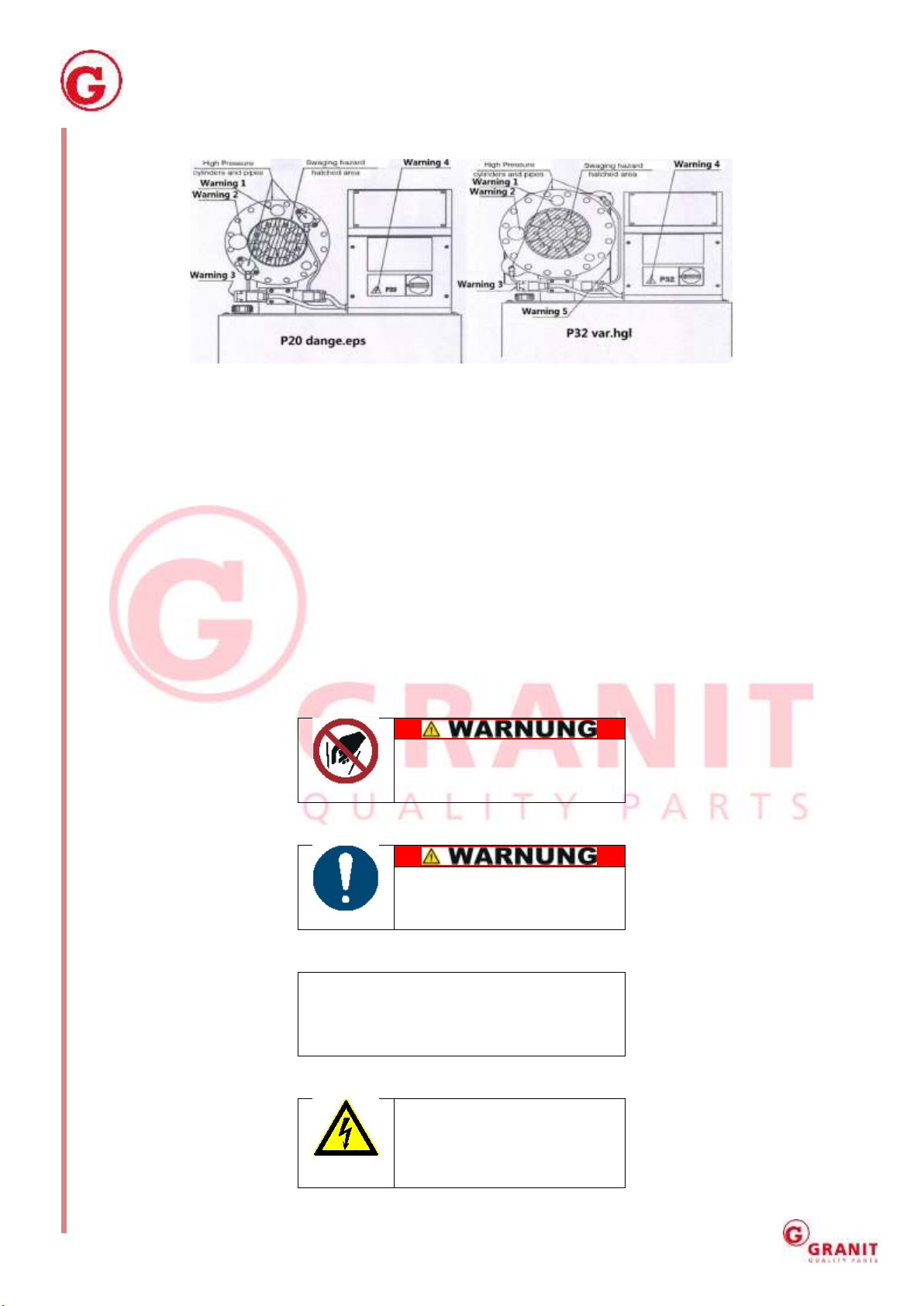
Warning of personal injury or environmental damage.
IMPORTANT
Warning of property damage.
NOTE
Additional information.
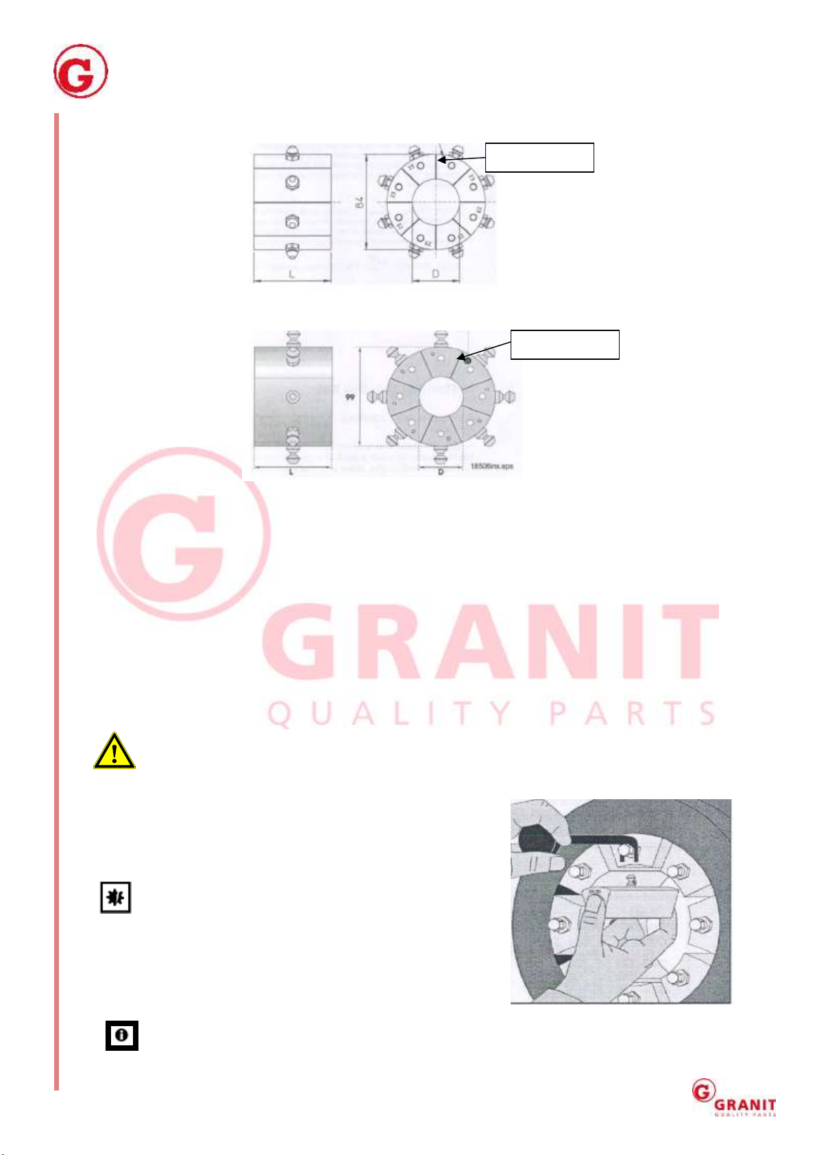
Numbers in illustrations (1, 2, 3 ...) refer to the corresponding numbers in brackets (1), (2), (3) ...
in the text next to the item numbers in the tables.
Instructions for which the order must be followed are numbered (1, 2, 3, ...)
Lists are marked with a dot (●, ●, ...)
2. Safety and accident prevention rules
2.1 General safety instructions
These operating instructions were prepared so that you can work safely with the equipment.
People who are not familiar with these instructions should not perform these actions.
Read these Operating Instructions thoroughly before use. Pay particular attention to the safety
instructions.
These Operating Instructions are intended for people with basic technical knowledge in using
equipment such as that described here.
If you have no experience with such equipment, you should first get assistance from experienced
persons.
Keep all supplied documents with the equipment for future reference if required. Keep the
purchase receipt for any warranty claims.
If you lend or sell the equipment, supply all documentation with it.
Observe the operating and maintenance instructions found in this manual.
Children should be supervised to ensure that they do not play with the equipment.
Mechanical maintenance should be performed at the prescribed intervals and in the prescribed
scope.
Following maintenance work, all dismantled protective devices must be properly reinstalled. The
protective devices and their protective functions should be inspected by a competent person
before using the machine.
Defective equipment must be repaired promptly in order to minimize the extent of damage and
avoid endangering the safety of the equipment.
The presses should only be used and operated under the conditions laid down in these operating
instructions.
Retrofits, changes or modifications to the equipment are strictly prohibited. They require
consultation with and written approval by the manufacturer.
If during operation (residual) hazards and risks become apparent which are not described in this
manual, the operator is obliged to report this to the manufacturer.
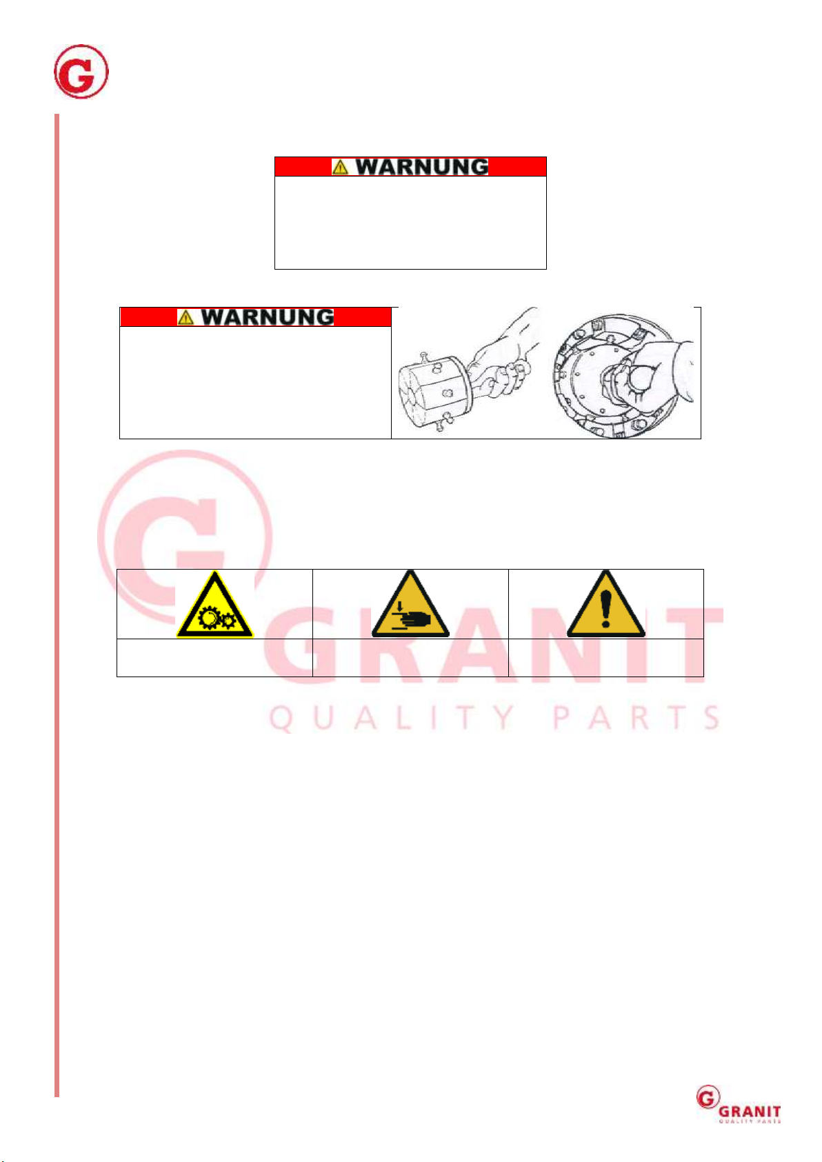
Never work or reach between or on moving pressing tools.
Do not change the settings of the safety components. Before each use check for proper
functioning, especially the hydraulic oil level, and check for possible leaks.
Liquid under high pressure can cause severe or fatal injury! In case of injury contact a physician
immediately!
Before working on the hydraulic system de-pressurize the system!

Operating Instructions for Hydraulic hose swage machine G20/G32
Page 4of 17
Regularly check hydraulic lines and replace if worn or aged! Replacement hoses must meet the
manufacturer’s technical specifications! If not otherwise specified by the manufacturer, replace
hydraulic hose lines at least after 6 years (due to aging)!
2.2 Precautionary measures
Always wear protective gloves when performing setup, maintenance and cleaning work
on the equipment, to prevent injury from sharp parts.
While working with and on the equipment wear protective work gloves that fit snugly,
safety goggles and work shoes.
Wear body-covering, snug-fitting clothing.
Before each use always perform a visual and then a function check of the equipment to
identify damage and worn parts and arrange for their repair by trained personnel before
use.
Ensure that the equipment is always on a solid and stable base.
Observe care and maintenance instructions.
The press may be operated only by persons 16 years or older. As an exception, use by a teenager
is permitted in the course of training to attain skill under the supervision of an instructor.
2.3 Transport and assembly
The press is delivered on a pallet. The palette can be
moved with a pallet jack or forklift. (Fig. 3)
After unpacking, lift the machine off the pallet with lifting
belts and place it in the desired location.
The dimensions are X = 76cm / Y = 56cm / Z = 80cm. The
total weight of the G20 is 138 kg and 208 kg for the G32.
F
igure 1
3. Intended use
The machine was developed to make hydraulic hose connections.
It is designed for use in dry, non-freezing interior spaces.
The press consists of a 3-phase (or 1-phase) electric motor that drives a hydraulic pump. The crimp
die is powered by the hydraulics.
The manufacturer shall not be liable for damages caused by failure to comply with generally
accepted rules as well as the instructions in this manual, including insufficient maintenance.
The manufacturer is not liable for any damages resulting from these causes.

Operating Instructions for Hydraulic hose swage machine G20/G32
Page 5of 17
4. Warnings on the machine
Figure 2
The machine is intended only for professional use. It should be operated only by trained personnel.
The openings between the matrices exceed 6 mm for technical reasons, and so are large enough
that they can crush a finger!
It is therefore absolutely necessary to observe the Operating Instructions and warnings in all
operating cycles of the machine.
Warnings are given as stickers on the machine and in these Instructions.
Do not remove or cover the warning stickers. Immediately replace damaged warning signs with
new ones.
Warning 1:
Keep body parts out of the
press as long as the drive
motor is running.
Warning 2:
Keep hands far enough away
from moving parts during
pressing.
Warning 3:
The crimping dies will open as soon as the
emergency off switch is operated. Use two-
hand control for normal operation.
Warning 4:
High voltage!
The electrics may be opened
only by a qualified electrician.

Operating Instructions for Hydraulic hose swage machine G20/G32
Page 6of 17
Warning 5: (G32)
The back of the “crimping head” is
covered by a housing that protects the
operator from the crush hazard behind it
between the rear flange and the cylinder.
This housing must not be removed!
Warning 6:
When changing the dies with the quick-
change device, hold the handle as shown
in the illustrations.
Make sure that your hand does not get
between the crimp elements.
For technical reasons, some die parts are not covered. Their travel is short and they move very
slowly. This limits the danger of crush injury, since the movement is small and the speed is low.
However, never let body parts get between these or any moving parts.
Additional warnings:
Warning of rotating machine
parts
Warning of hand injury
General warning
The noise developed by the equipment in operation has been measured as no higher than 70dB(A).

Operating Instructions for Hydraulic hose swage machine G20/G32
Page 7of 17
5. First use
5.1 Filling with hydraulic oil
Fill the oil tank to the middle of the two markings on the dipstick. Use a hydraulic oil like Shell Sagen
T46 or equivalent. The tank volume is 32 litres. We recommend filling the oil tank through a 20-y
filter in order to keep possible contamination out of the system.
5.2 Electrical connection
DANGER: Before connecting the machine make sure that the supply voltage is identical to the
required machine voltage (see type plate). For more information, consult your power
supplier. Insert the supply cable through the hole in the side panel of the electrics cabinet and secure
it with a strain relief plug.
3-phase motor: Connect phase conductor with terminals L1, L2 and L3 in the electrics cabinet.
Connect the ground wire to the ground terminal on the mounting plate. Check the connection
against the circuit diagram in the spare parts list. Make sure that the motor’s direction of rotation is
the same as the arrows on the motor illustration. If the motor is running in the wrong direction, the
two-phase conductors need to be switched on their terminals.
1-phase motor: Connect the phase and the neutral conductor to the respective terminals in the
electrics cabinet. Connect the ground wire to the ground terminal on the mounting plate. Check the
connection against the supplied circuit diagram.
DANGER: This work may only be done by a qualified electrician. Fatal shock hazard!

Operating Instructions for Hydraulic hose swage machine G20/G32
Page 8of 17
6. Operating the equipment
6.1 Control elements
1. Motor on and off switch. This separates the machine from the power supply. But the
undervoltage release can only be disconnected by pulling the plug or disconnecting the power
cable.
2. Pressing the crimp button moves the matrices until the button is released or the set crimp
diameter is reached.
3. Pressing the opening button opens the matrices until the button is released or the maximum
return travel is reached.
4. Crimping diameter display
5. The crimp diameter chart for each die set and the associated setting display.
NOTE: For good results, the parameters should always be set specifically for the individual
hose connection.
6.2 Crimping controls
The main controls are on the front of the machine.
(A) Close the die: (B) Open the die:
1. Semiautomatic machine control
This button starts the crimping motion, if the matrices have reached the set return position. (A)
2. Crimp button
The matrices move when this button is pushed. The matrices continue moving until the button is
released or the set crimp diameter is reached. This button can only be used if the machine is in
manual mode. If the machine is started in manual mode, the crimp button cannot be used to start
crimping until the 0 position or the opening dies have been set with return button 7. The matrices
will not open if they have reached the set return position. (B)
3. Reaching the set crimp diameter
The signal light comes on when the matrices have reached the set crimp diameter. (A)
4. Return button
The matrices open when this button is pushed. The matrices continue to open until the button is
released or the set return diameter is reached. This button can only be used if the machine is in
manual mode. (B)
5. Return diameter reached
The signal light comes on when the matrices have reached the set return diameter. Automatic
operation cannot start until the return position has been reached.

Operating Instructions for Hydraulic hose swage machine G20/G32
Page 9of 17
6. Delay indicator light
The delay indicator light comes on when the delay function is active.
7. Return diameter check
The return diameter of the matrices after crimping is set with the dial face. Set the return large
enough that the connector to be crimped fits easily between the matrices but has minimal play.
Turning the dial face clockwise increases the return.
8. Crimp diameter check
The crimp diameter is adjusted by means of the dial face and the die set used. The dial face covers 0
to 10 mm. It is graduated in 0.01 mm or 0.1 mm increments. Turning the dial face clockwise increases
the return. On the IS models, one turn equals a 1 mm change in the crimp diameter. On the AS
models the crimp diameter changes by 1 mm between two numbers.
6.3 Test run
1. Start the motor.
2. Set the crimp diameter to 10.0 and the return to the maximum amount.
NOTE: During the first crimp cycles the air in the cylinders can cause the matrices to move
irregularly.
3. Repeat the crimp cycle a few times until the movement is regular.
To prevent accidents, make sure that there are no foreign objects between the matrices.
NOTE: If the matrices do not move in both directions, the motor is running in the wrong
direction. Correct this by switching the two-phase conductors in the switchgear cabinet.
4. Test the operation of each button and each setting in the table per Chapter 6.1.
Observe also the information in the VS Operating Instructions.

Operating Instructions for Hydraulic hose swage machine G20/G32
Page 10 of 17
6.4 Die selection
G20, see Figure 5
Figure 5
G32, see Figure 6
Figure 6
Use only intact die sets approved for the device.
Observe the manufacturer’s specifications for the right crimp diameter. The smallest crimp diameter
is marked on the die with a “D.”
Example: On die set NO 18013/10 the minimum crimp diameter is 10 mm.
6.5 Changing a matrix
1. Start the motor and press the return button until the matrices have reached their maximum
return.
2. Stop the motor.
3. Matrices may be installed only with the motor off.
DANGER: The motor must be switched off and secured against starting before doing any
repair and maintenance work. If this is not done, there is a danger of uncontrolled starting,
resulting in severe injury.
4. Using the tool supplied, pull on the pin of the matrix to be
switched out.
5. Before installing matrices, clean the contact surfaces of the
two joining components.
IMPORTANT: Avoid damaging the dies themselves and
their contact surfaces.
6. Place the replacement matrix in the space holding it by the
pin with the tool. The number on the matrix must face you.
7. Remove the tool.
Figure 3
NOTE: To get a clean connection, after replacement check the seating and movement of the
matrices as described in Chapter 6.2.
Diameter
Diameter

Operating Instructions for Hydraulic hose swage machine G20/G32
Page 11 of 17
6.6 Die sets
Figure 4
Set the crimp diameter MS using the crimp diameter chart on the door of the switchgear cabinet.
It shows the die set numbers and corresponding crimp ranges.
The upper part of the chart shows the selector position for each crimp diameter.
Crimping in the grey area of the chart is not recommended. The crimp diameter selector knob is
factory-calibrated so that when the dial face shows 0.0 the diameter is the minimum for the die set
used, i.e. with die set 20-16 the crimp diameter is 16 mm.
One full turn clockwise with the dial face adjustment knob adds 1 mm crimp diameter. Chart
20chart_MS_new.eps corresponds to 1/100mm on the scale.
EXAMPLE:

Operating Instructions for Hydraulic hose swage machine G20/G32
Page 12 of 17
The manufacturer has specified a crimp diameter of 20.6 mm for assembly. Select die set 20-19 (min.
crimp diameter 19 mm) per the chart. Turn the knob to position 1.60 (upper scale 1, lower scale 60).
This setting gives a crimp diameter of 20.6 mm (19 + 1.6 mm).
The machine is factory-calibrated for 40 bar pressure. That means that crimping a connection
requires 40 bar.
The crimp diameter chart for the G32MS has a precision of +/- 0.1 mm (not counting possible elastic
recovery of assembly) for the setting of the scale on the crimp diameter dial face.
If components need to be crimped at higher pressure, due to machine discrepancy the crimp
diameter can be higher than the amount on the scale. In this case the crimp diameter must be
corrected by adjusting the setting.
6.7 Crimping connections
DANGER: When crimping hold the hose as far away as possible from the crimping point, for
safe guidance in the press. Crimping can cause amputation!
1. After installing the right die set and setting the crimp diameter, lay the hose and connection in
the die.
2. Press the Crimp button and keep it pressed until the set diameter is reached.
3. Press the Return button and take out the crimped assembly.
4. Check the result and measure the diameter. If necessary, correct the set value and recrimp.
NOTE: For faster and reliable results, make a diagram with the different hose / assembly
combinations and die sets plus settings.
7. Care and maintenance
1. The inside surface of the conical flange must be lubricated daily with a pressure-resistant
grease like Optimol Viscogen 4.
2. Apply the grease with a small brush to the conical surfaces on the front and back of contact
surface.
3. The piston rod must not be greased.
4. Lubricate the matrices daily with a pressure-resistant grease like Optimol Viscogen 4.
5. Maintain the equipment at the end of each working day. Figure 5
Figure 6

Operating Instructions for Hydraulic hose swage machine G20/G32
Page 13 of 17
8. Calibration of the crimp diameter
NOTE: The crimp diameter dial face was calibrated during testing in manufacture.
1. Calibrate the crimp diameter using a seamless steel tube of 25 mm diameter and 2 mm wall
thickness. Use die set 20-19 (G20) or 32-19 (G32).
2. Move the dial face 1.0 so that the crimp diameter is 20 mm (see Fig. 11 below) and lock the
setting. Crimp the tube and measure the real diameter.
3. Remove the adjustment knob (without changing the position of the selector disc).
4. Open the dial face lock and set the dial face to the real diameter measured on the steel tube.
Unlock the setting and correct it correspondingly.
5. Set the dial face to the right diameter and crimp the steel tube again.
6. The machine is calibrated when the real diameter is the same as the amount set at the machine.
If not, repeat steps 2 through 5.
7. After setting, the crimp result should the minimum rated crimp diameter of the dial set used, and
the dial face should be at 0 turns.
Figure 7
9Disposal
The separate, environmentally friendly disposal of materials encourages recycling of materials.
Therefore, after expiry of the normal service life, the equipment itself and all related components,
including the lubrication, packaging and wear parts, should be disposed of at a recyclables collection
point.
Packaging, equipment and accessories are made of recyclable materials and should be disposed of
accordingly.
If the unit is no longer serviceable, make sure it is unusable before disposal.
DANGER: If you do not have the necessary expertise, engage a specialist for dismantling and
disposal. INJURY HAZARD!
!!! Always observe local disposal regulations!!!

Operating Instructions for Hydraulic hose swage machine G20/G32
Page 14 of 17
10 Fault rectification
Fault
Possible cause
Action
Machine will not
start
1. No electrical current
2. Motor protection triggered
3. Switch defective
4. Voltage too low
Check the fuses and cable connections.
Try again. Check the motor and pump.
Check the voltage supply.
Motor runs but
matrices do not
move
1. Wrong direction of rotation
2. Insufficient oil
3. Fuse defective
4. Setting controls defective
5. Valve defective or stuck
6. Pump coupling defective
Switch two phases at cable connection
Check the oil level
Check fuse and replace if necessary
IS/AS check VS model read fault code and
check valve
Check connection and replace if necessary
Insufficient
crimp force
1. Insufficient lubrication
2. Oil level too low
3. Pressure control valve stuck
4. Oil leak
5. Play in connection between
pump and motor
Grease matrix holder
Add oil
Inspect and clean
Check and seal if necessary
Check connection and replace if necessary
Divergent crimp
diameter
1. Insufficient lubrication
2. Dimension changed
3. Adjustment knob loose (MS)
4. Adjustment knob loose (IS/AS)
5. Adjustment knob defective
(MS)
6. Adjustment knob defective
(IS/AS/VS)
7. Valve defective or stuck
Grease matrix holder
Check dimensions
Check, calibrate and tighten
Inspect and replace
Inspect and clean
DANGER: If you do not have the necessary expertise, engage a specialist for dismantling and
disposal. INJURY HAZARD!

Operating Instructions for Hydraulic hose swage machine G20/G32
Page 15 of 17
11 EC declaration of conformity
EC Declaration of Conformity for Machinery (EC - Directive 2006/42/EC)
The distributor,
Wilhelm Fricke SE
Zum Kreuzkamp 7
D-27404 Heeslingen, Germany
hereby declares on its sole responsibility that the Hydraulic Line Crimp Device
Type/series identification: G32 and G20
is in conformity with the provisions
of Machinery Directive 2006/42/EC. Appendix I
The product was developed in accordance with the following standards:
EN 60204-1:2006/AC:2010
EN ISO 12100:2010
Technical documentation is kept by:
Arndt Strate, Wilhelm Fricke SE
The serial number and model year are shown on the type plate of the equipment.
Heeslingen, 28 July 2017
(Managing Director)

Operating Instructions for Hydraulic hose swage machine G20/G32
Page 16 of 17
12. Guarantee
The warranty terms of Wilhelm Fricke SE, as can be found in the sales documents and the current
version of the Terms and Conditions, apply.
In case of questions, please contact the company's customer service line.
13. Addresses
Sales/Customer Service / Tel.: +49 (4281) xxxx
Spare parts sales: Fax: +49 (4281) xxxx
Postal and shipping address: Wilhelm Fricke SE
Zum Kreuzkamp 7
D-27404 Heeslingen
14. Legal Notice
Original Operating Instructions for Hydraulic Line Crimp Device G20 and G32
Manufacturer: Wilhelm Fricke SE - D-27404 Heeslingen
1st Edition of July 2017
©2017 Wilhelm Fricke SE
Reproduction in whole or in part is prohibited without the written consent
of the Wilhelm Fricke SE company.
All names of products mentioned in these Operating Instructions are trademarks of their
respective companies.
Printed on paper made from chlorine and acid-free bleached pulp.

Operating Instructions for Hydraulic hose swage machine G20/G32
Page 17 of 17
15. Circuit diagrams
15.1 Electrical control:
15.2 Hydraulic circuit diagram
This manual suits for next models
5
Table of contents
Popular Crimping Tools manuals by other brands

KUDOS
KUDOS HD-BGD3 SAFETY OPERATING & MAINTENANCE INSTRUCTIONS

molex
molex 207128 Series Specification sheet

TE Connectivity
TE Connectivity PRO-CRIMPER III instruction sheet

Emerson
Emerson klauke ESM 35CFM quick start guide

molex
molex 207129 Series Specification sheet

Tyco Electronics
Tyco Electronics PRO-CRIMPER III instruction sheet

Tyco Electronics
Tyco Electronics PRO-CRIMPER III instruction sheet

HSS Hire
HSS Hire 68613 Operating & safety guide

Hilpress
Hilpress 17000 operating instructions

Eaton
Eaton ET1000 Operator's manual

Greenlee
Greenlee GATOR EK12ID instruction manual

Tyco Electronics
Tyco Electronics PRO-CRIMPER III instruction sheet