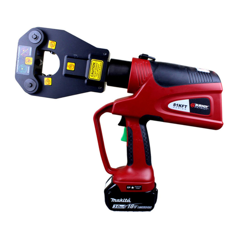
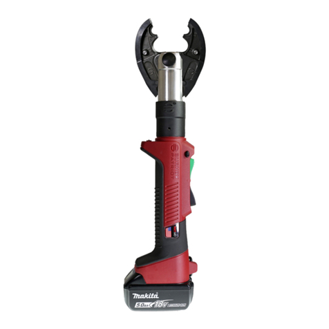
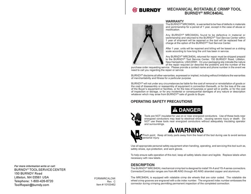
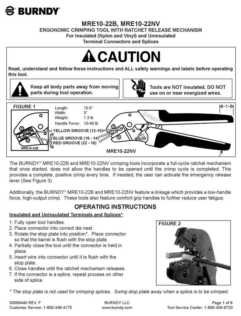
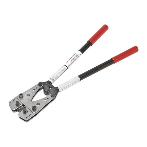
Burndy HYTOOL MD6 Series Maintenance and service guide

© BURNDY LLC, 2020
MD6 SERIES
HYTOOL™
SAFETY
OPERATING &
MAINTENANCE
INSTRUCTIONS MD6, MD6-6, MD6-37, MD6-38
BURNDY®ENGINEERED SYSTEM
For connection installation information,
scan this code with your mobile device.

2
TABLE OF CONTENTS
Safety Information ...................................................... 3
Introduction & Specications ...................................... 4
Accessories ................................................................ 5
Features & Benets.................................................... 6
Tool Alignment Inspection........................................... 6
Component Identication............................................ 7
Parts List..................................................................... 8
Tool Operation Procedures......................................... 9
Care & Maintenance................................................... 9
Cleaning Recommendations ...................................... 9
Tool Variations ............................................................ 9
Accessories (Pictorials) ............................................ 10

3
For information only contact:
BURNDY® Tool Service Center
150 Burndy Road
Littleton, NH 03561
Or Call, Toll Free 1-800-426-8720
Additional or replacement manuals may be obtained free
of charge from the BURNDY®Tool Service Center.
SAFETY INFORMATION
The above symbols are used to call your attention to
instructions concerning your personal safety. Look for
these symbols; read and follow the instructions that
accompany them. Failure to follow the safety information
provided can lead to serious personal injury or death.
Hazards that, if not
avoided, will result in
severe injury or death.
SYMBOL MEANING
Hazards that, if not
avoided, could result in
severe injury or death.
Hazards that, if not
avoided, could result
in minor or moderate
injury.
Read and follow the operator's manual
before using tool.
Wear eye protection and personal
protective equipment.
SAFETY FIRST
The information provided in this manual is
essential for the safe handling, operation,
and maintenance of the BURNDY®
MD Series. The operator must read,
understand, and follow these instructions
and ALL safety warnings and labels before
operating these tools.
• Only use these tools in accordance with the
manufacturer’s specications. Other use of these
tools may lead to serious personal injury or death.
Each employer shall instruct each employee and user
in the recognition and avoidance of unsafe working
conditions and the laws and regulations applicable to his/
her work environment to control or eliminate any hazards
or other exposure to illness or injury. Reference: US
OSHA 29CFR 1910 et seq.
If a conict arises between the material contained in this
manual, rules of the user, his/her employer or company,
and legal or industry guidelines the more stringent rules
take precedence and must be followed.
Observe and follow all other safety rules and regulations
for the job.
Safety is everyone’s responsibility.

4
Use
Tools have been specifically designed for use with
BURNDY®products. Use of non-BURNDY®products is
limited to those which conform to BURNDY®technical
specications applicable to Tools. Use of non-BURNDY®,
non-conforming products with the tool shall be deemed
misuse or abuse.
TYPE MD6 HYTOOLTM
Hand-Operated Tool
The MD6 TYPE HYTOOLTM series are hand operated
tools that use permanent die grooves, and/or insertable
BURNDY®“W” type dies. They install a full range of
BURNDY® connectors including service entrance, splices,
terminals, stacking lugs, street light, stirrup, and repair
sleeves, etc. Certain versions are available for specic
installation applications. The MD6-8 installs almost all of
the line, pole, and house connections in the BURNDY®
Compression Connector Program with only one (1) extra
die set, the W-BG. The tool has two (2) permanent die
grooves, “O” and “D3” for distribution tap connectors.
The “D3” groove also serves as a seat for die inserts to
install additional connectors. The die inserts snap into the
permanent “D3” die holder groove easily with one hand,
and are secured with the spring loaded, positive lock, die
retainer buttons.
All MD6 tools incorporate an over center toggle action
mechanism allowing for easy crimping operations, and
eld adjustability.
OPERATING SAFETY PRECAUTIONS
This tool is NOT insulated for use on or
near energized conductors. Use of this
tool near energized conductors may lead
to electrical shock, causing severe injury
or death.
Pinch point hazard. Tool jaws operate at
high speed and force and can cause severe
personal injury. Keep all body parts away
from moving parts of the tool, especially
the area of the head and indenters during
operation.
Do NOT over-reach while operating this
tool. Loss of balance can cause serious
personal injury or death. Move closer to
work area and securely support yourself
and your work. ALWAYS keep proper
footing and balance.
Projectile hazard. Wear eye protection and
personal protective equipment.
Explosive hazard. Do NOT use tool in an
explosive environment.

5
FOR USE ON:
•Copper taps from #10 solid - #2/0 Stranded
• Aluminum/ACSR taps from#14 solid -#4/0 ACSR
• Stirrups from #6 Awg - #4/0 ACSR
• Copper & Aluminum code conductor connectors from
#6 Awg - #4/0 stranded
• Overhead Full Tension Deadend, Full & Non Tension
Splices & Terminals from #10 stranded - #4/0 ACSR
• 5/8” & .840” Service entrance sleeves
• INSULINKTM type ES (insulated) #10 - #1/0 Awg
• LINKITTM type YSU (bare) #8 - #1/0 Awg (YSD-#4/0)
• HYDENTTM CU & AL terminals/splices #8 - #4/0 Awg
• HYSPLICETM for Copper, copperweld, & AAC
conductors
• UNISPLICETM for AAC, ACSR, AAAC conductors
• HYPLUGTM, HYSEALUGTM, & HYSEALPLUGTM
connectors
• Stacking HYLUGTM and disconnectable terminals
Please refer to the BURNDY®Master Catalog for more
detailed use and application data.
SPECIFICATIONS
Crimp Force Developed.................9,000 lbs. (4,091 kg)
Weight (tool only)......................................6 lbs. (2.7 kg)
Tool lengths
MD6, MD6-6, & MD6-8 ..................... 25-⅜” (645 mm)
MD6-37, MD6-38 .............................21-⅝” (549 mm)
ACCESSORIES
•Vinyl jaw edge covers for all ..........Catalog#MD6CP1
MD6 type tools except MD6-6
• Neoprene jaw cover for..................Catalog #PT6744
MD6-6 “snub-nose” tool
• Metal carry case...........................Catalog #PT4952-1
Holds (1) tool and up to 18 “W” dies
• Canvas carry bag hold all................Catalog #PT4925
styles of MD tools & 9 “W” dies
• Plastic Case, Holds 12 sets of W-dies...CASEWDIES
• Cutter dies for #4 - #4/0.....................Catalog #W-28K
ACSR, Aluminum, Copper

6
BENEFITS
• Long life, ease of operation due to bent handle de-
sign
• Proper crimps are assured with butting jaws
• Easily eld adjustable with orange alignment groove
for visual check
• Lasts up to 5 times longer than imitations - still work-
ing when others have long since worn out
• No lost dies and easy, one hand die insertion
• Uses most all of BURNDY®“W” & “X” die inserts
• Increases life of tool by reducing tool wear and
friction
FEATURES
• High strength bent, hickory wood handles on types
MD6, MD6-6, MD6-8, MD6-37, MD6-38
• Time-proven steel jaw design
• Adjustable tool mechanism
• 90,000+ crimp/cycle life
TOOL INSPECTION & ADJUSTMENT PROCEDURE
Tools should be checked periodically for correct adjustment. As with any tool, a slight amount of wear may occur
over time. This wear may be corrected by readjusting the MD6 type tool(s) as follows:
• Positive lock, spring loaded die retainer buttons
• Permanent “D3” die groove
• PTFE impregnated steel/bronze bushings and stain-
less steel pins
Adjusting Set
Screw
Locking Set
Screw
CORRECT: Index Marks Line Up
Adjustment Required
1. Remove any die inserts from the tool and make sure
the jaw tips are free of dirt, etc.
2. Open tool and close handles until jaw tips just touch.
DO NOT CLOSE HANDLES COMPLETELY!
3. Check that the index marks (orange grooves) on the
toggle link and frame line up.
4. If the marks line up, the tool is in proper adjustment.
5. If they do not line up, loosen the locking set screw us-
ing a 1/4” (6.4 mm) hex key, then turn the adjustment
screw clockwise or counter-clockwise until the marks
line up.
6. Tighten the locking set screw securely; your tool is
now properly adjusted and ready for use.

7
MD6 JAW ASSY.
PT4911
MD6-6 JAW ASSY.
PT6760
MD6-8 JAW ASSY.
PT6752-1
JAW LINK
PT4902
NON-ADJUSTABLE
FRAME ASSY
PT4995
DIE BUTTON
REPAIR KIT
PT4931-1
PT4903-1
PT4914
PT4904-1
PT4915
HARDWARE
ADJUSTING
SET SCREW
LOCKING
SET SCREW
ADJUSTABLE
FRAME ASSY.
PT4994
MD SERIES HYTOOLTM

8
Sub Assemblies Part Number Qty. Description
MD6 Jaw Assy.
PT #4911
MD6-6 Jaw Assy.
PT #6760
MD6-8 Jaw Assy.
PT #6752-1
PT4901-1 2 MD6 Jaw
PT6754-1 2 MD6-6 Jaw
PT6739-2 2 MD6-8 Jaw
PT4923 2 Lubricated Bushing
PT30303 2 Die Pin
PT6799 2 Pin
PT4909-1 2 Die Button
PT30304 2 Die Pin Spring
PT4902 2 JawLink
PT4903-1 2 Link Bolt
PT4914 2 Flexloc Thin Nut
Adjustable
Frame Assy. PT4994 1 Handle, WADJ. Screws
Non-Adjustable
Frame Assy. PT4995 1 Handle, Fixed
Hardware PT4904-1 3 Splined Shank Frame Bolt
PT4915 3 Flexloc Thin Nut
ACCESSORIES
Die Button
Repair kit
PT #4931-1
Misc.
PT4909-1 2 Die Button
PT30303 2 Die Pin
PT30304 2 Die Release Spring
MD6OMI 1 Operating & Maintenance Instruction Manual
MD6 SERIES HYTOOLTM PARTS LIST
1 NOTE: If Die Button Assy. is requested Part No.4931-1 (two die button assemblies) will be supplied.
1

9
TOOL OPERATION PROCEDURE
Only crimp dies and accessories designed and
manufactured by BURNDY®are recommended for
use with the BURNDY®MD6 HYTOOLTM. Use of non-
BURNDY®, non-conforming products with the BURNDY®
MD6 HYTOOLTM shall be deemed abuse and will void
the warranty.
Call BURNDY®Technical Services at 1-800-346-4175,
with any application questions if in doubt.
1. Select the proper dies for the connector to be crimped.
(Refer to the BURNDY®Master Catalog.)
2. Check die recommendation chart for compatibility with
MD6. If recommended, refer to catalog and chart for
number of crimps required for proper installation.
3. Install dies in jaws making certain that they are
properly secured by the spring loaded, positive lock,
die buttons.
4. IMPORTANT - To help minimize hand and arm
fatigue and perceived handle force during use, it is
recommended to hold the MD6 HYTOOLTM with your
hands at the end of the handles.
5. Insert conductor into the connector and align the
tool and die on the connector. Start in the center for
splices and “H” frames, and on the end, nearest the
pad, for terminals.
6. Operate the tool by closing, and allowing, the handle
butt/stop blocks to touch. Normally a “pop” will be
heard as the tool goes over center after the crimp
is made.
7. Continue crimping the connector until the correct
number of crimps have been completed. Work from
the center to the outer edges for splices and “H” frame
connectors, alternating sides if possible, for the best
compression connection.
8. Reposition tool for next crimp, if required. Unless non-
bowing dies are used, it is recommended that the tool
TOOL VARIATIONS:
MD6 Standard MD6 with permanent “BG (5/8”) and
“D3” grooves.
be rotated 90° for each adjacent crimp on large splice
connections.
CARE & MAINTENANCE
Your MD6 TYPE HYTOOLTM has been thoroughly tested
and lubricated by the factory. Extended trouble-free
service can be assured by following these simple steps:
1. Keep the tool clean at all times. Remove dirt, debris,
and other foreign substances from external surfaces
daily, to help prevent corrosion and damage to the
tool and mechanism.
2. Lightly lubricate every two (2) months with a good
grade machine oil in between the handle pivots and
all rubbing surfaces as needed.
3. Store the tool in either the optional tool bag or metal
carry case, when not in use. Keep in a dry, moisture
free area.
CLEANING RECOMMENDATIONS:
1. Spray jaws with CHEM-CleanTM, or equivalent, solvent
to loosen contaminants.
2. Using a stiff fiber brush, (never metal) remove
contaminants in and around jaw mechanism and
allow solvent to drain o tool.
3. Use air nozzle to remove any solvent residue.
4. Lubricate according to Care & Maintenance
instructions.
MD6-6 “Snub-Nose” variation of MD6 has a
permanent “D3” groove in jaw.
Recommended for use where space for
tool jaw is limited.
MD6-37 Permanent 161,162,163, & 171 dies
MD6-38 Permanent K, BG, & C dies in jaw

10
ACCESSORIES:
CARRYING BAG
Part 4925
Sturdy canvas bags for storage and
protection of MD6 tools, and variations,
and 9 die sets.
CABLE CUTTER DIES
Catalog No. W28K
Permits use of MD6 as cable
cutter. Range: #4-4/0 ACSR
aluminum or copper.
“Non-Bowing’’ Dies
For Installing
UNISPLICE™
Catalog Nos. W-687, &
W-702
Install one-piece, full tension
sleeves on ACSR without
bowing. Range: W-687 installs
YDS4RL and YDS2RL. W-702
installs YDS021RL and
YDS25RL.
Neoprene Cover
For MD6-6 Jaws
Part 6744
Semi-rigid Neoprene cover designed to
help protect MD6-6 and operator against
accidental brush contact with energized
conductors. Field installed.
Vinyl Covers for MD6 and MD6-8 Jaws
Part MD6-CP1
Laminated vinyl covers help protect MD6 and operator against accidental brush contact
with energized conductors without obstructing vision. Covers snap easily into place over jaw
edges. Supplied in set of two covers.
CARRYING CASE
Part 4952-1
Provides storage and protection for
MD6 tools, with or without covers
and 18 die sets. Tool and die sets
not included.
CASEWDIES
Part 10097050
Plastic Case, Holds 12 sets of W-Dies

11

12
Reorder Form 3019
Rev. H
Item #464750
For more information write or call:
BURNDY®TOOL SERVICE CENTER
150 Burndy Road
Littleton, NH 03561 USA
or call, toll free 1-800-426-8720
ToolRepair@burndy.com
This manual suits for next models
4
Table of contents
Other Burndy Crimping Tools manuals
Popular Crimping Tools manuals by other brands

Greenlee
Greenlee GATOR EK1550LX Operation manual

Tyco Electronics
Tyco Electronics ROTA-CRIMP 68321-1 instruction sheet

Danfoss
Danfoss FT1244 Operator's manual

VETEC
VETEC SPM32-18 instruction manual

molex
molex 207129 Series Operating Instruction and Specifications Sheet

Apollo
Apollo PEX 69PTKH00143 instruction sheet