MM CAR 35 User manual

USE, MAINTENANCE, AND SPARE PARTS MANUAL
MODELS: wheelbarrow sprayers 35L-50L-70L - 90L - 120L
wheelbarrow sprayers 200L - 300L - 400L

Use and maintenance manual
2
WHEELBARROW SPRAYERS
TABLE OF CONTENTS

Use and maintenance manual
WHEELBARROW SPRAYERS
3
INTRODUCTION ..........................................................................................................................................................5
DESCRIPTION OF THE MANUAL'S BASIC CONTENTS .....................................................................................................5
1INFORMATION ABOUT THE MANUAL..................................................................................................................5
1.1 UPDATES TO THE MANUAL...................................................................................................................................5
1.2 COPYRIGHT...........................................................................................................................................................6
1.3 WARRANTY...........................................................................................................................................................6
1.4 TERMS OF DELIVERY .............................................................................................................................................6
1.5 JURISDICTION.......................................................................................................................................................6
1.6 TRANSPORTING THE WHEELBARROW SPRAYER...................................................................................................6
1.7 PACKAGING ..........................................................................................................................................................7
2INFORMATION ABOUT THE WHEELBARROW SPRAYER........................................................................................7
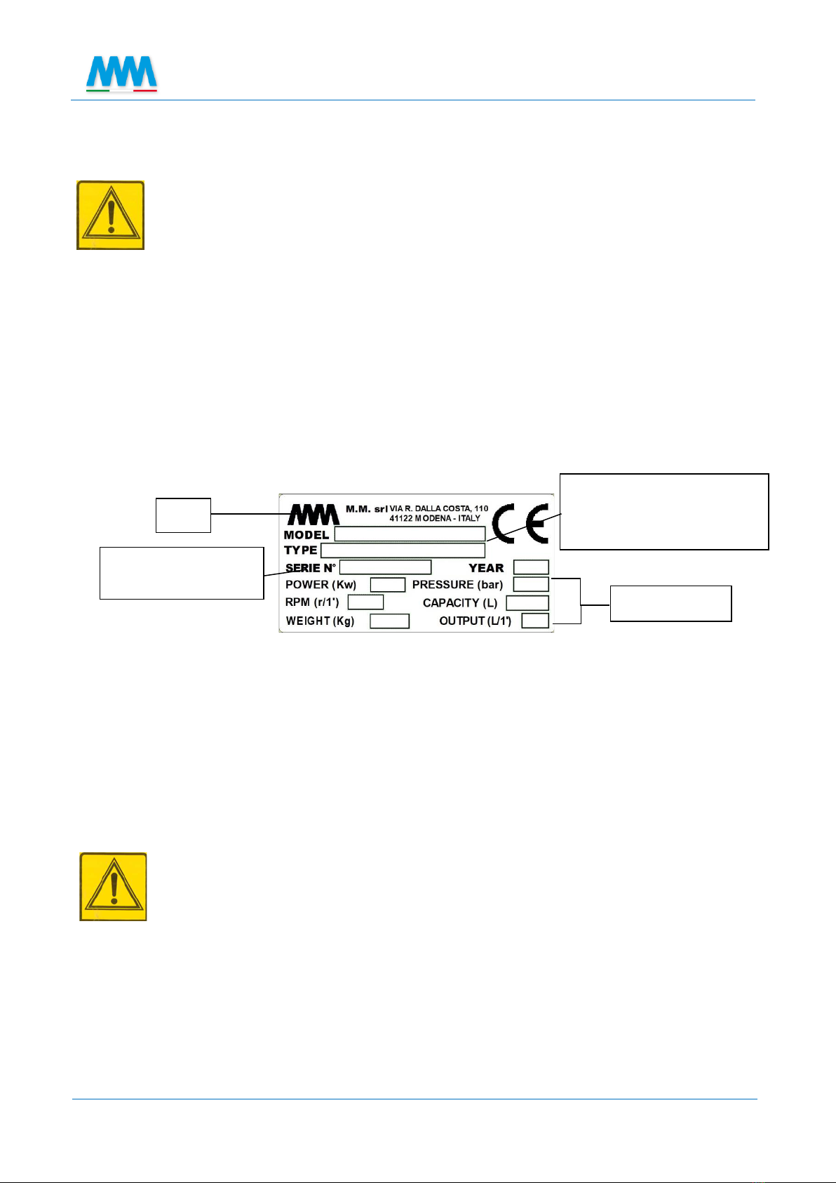
2.1 WHEELBARROW SPRAYER IDENTIFICATION.........................................................................................................7
2.2 INTENDED USES....................................................................................................................................................7
2.3 DESCRIPTION........................................................................................................................................................8
2.4 TECHNICAL DATA AND COMPONENT IDENTIFICATION ........................................................................................8
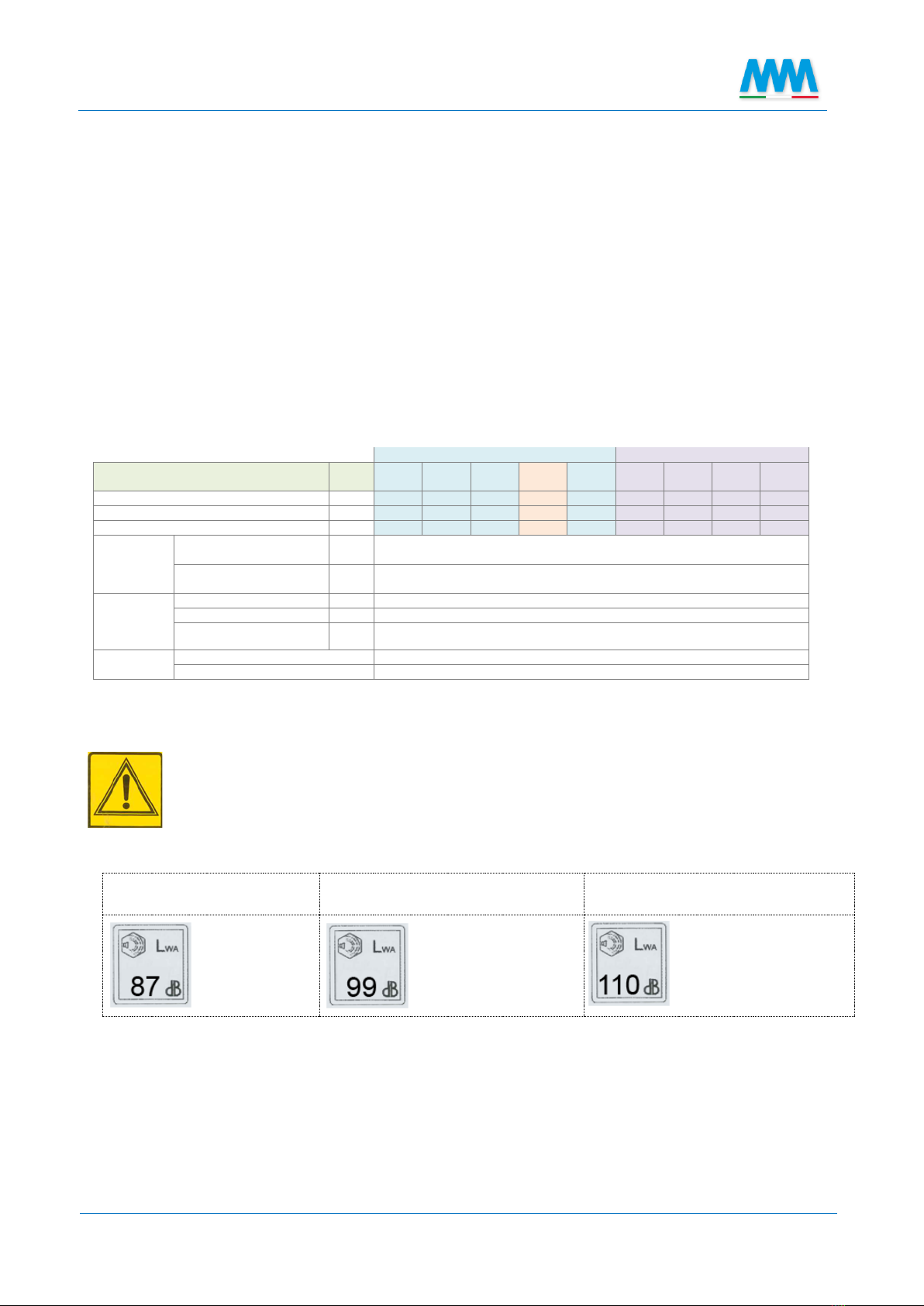
2.5 NOISE LEVELS........................................................................................................................................................8
2.6 SAFETY STANDARDS AND USES NOT PERMITTED .................................................................................................9
2.7 ELECTRIC MOTORS (BATTERY, 230V AND 400V).................................................................................................11
2.7.1 SAFE USE OF THE MOTOR, BATTERY AND BATTERY CHARGER......................................................................11
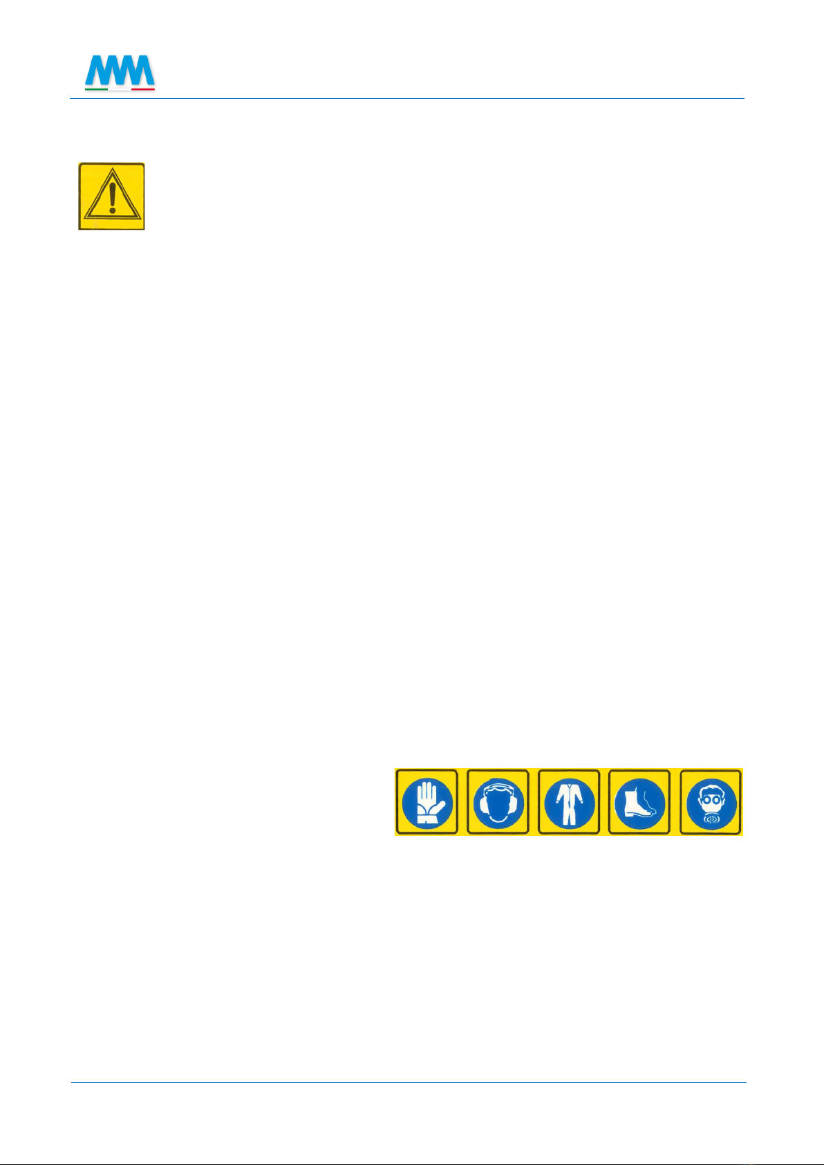
2.8 SAFETY SIGNAGE ................................................................................................................................................12
2.8.1 LOCATION OF THE PICTOGRAMS ON THE WHEELBARROW SPRAYER ...........................................................12
2.8.2 SAFETY AND DESCRIPTION PICTOGRAM LABELS............................................................................................13
3PLANT PROTECTION PRODUCTS........................................................................................................................14
3.1 ENVIRONMENTAL PROTECTION.........................................................................................................................14
4WHEELBARROW SPRAYER FUNCTIONALITY.......................................................................................................15
4.1 WATER CIRCUIT SCHEME....................................................................................................................................15
4.2 DESCRIPTION OF THE MACHINE .........................................................................................................................15
4.3 COMPONENT POSITIONING ...............................................................................................................................17
4.3.1 TANK ..............................................................................................................................................................18
4.3.2 SUCTION FILTER .............................................................................................................................................18
4.3.3 PRESSURE REGULATOR ..................................................................................................................................18
4.3.4 PUMP (see the attached use and maintenance handbook)...........................................................................19
4.3.5 MOTOR (see the attached use and maintenance handbook) ........................................................................19
4.3.6 LEVER LANCE..................................................................................................................................................19
4.3.7 HOSE REEL (optional) .....................................................................................................................................19
4.3.8 BOOM (optional)............................................................................................................................................20
5WHEELBARROW SPRAYER FUNCTIONALITY.......................................................................................................20
5.1 WHEELBARROW SPRAYER ASSEMBLY ................................................................................................................20
5.1.1 MOUNTING THE WHEELS...............................................................................................................................21
5.1.2 DRAWBAR ASSEMBLY (4-wheel models)........................................................................................................21
5.1.3 HOSE REEL ASSEMBLY (OPTIONAL)................................................................................................................21
5.1.4 BOOM ASSEMBLY (OPTIONAL).......................................................................................................................22
5.2 FILLING THE TANK...............................................................................................................................................22
5.3 HAND WASH TANK (OPTIONAL) .........................................................................................................................23
5.4 BATTERY OPERATED MODELS.............................................................................................................................24

Use and maintenance manual
4
WHEELBARROW SPRAYERS
5.4.1 MODELS FOR PROFESSIONAL USE..................................................................................................................25
5.5 PRELIMINARY CHECKS ........................................................................................................................................26
6SPRAYING.........................................................................................................................................................27
7CLEANING THE WHEELBARROW SPRAYER (TO BE PERFORMED AFTER EACH USE)..............................................28
8WHEELBARROW SPRAYER MAINTENANCE ........................................................................................................29
8.1 ROUTINE MAINTENANCE ...................................................................................................................................29
8.2 OBLIGATION TO INSPECT THE EQUIPMENT FOR THE DISTRIBUTION OF PLANT PROTECTION PRODUCTS (FOR
PROFESSIONAL USE) ..............................................................................................................................................................30
8.3 EXTRAORDINARY MAINTENANCE.......................................................................................................................32
8.4 STORAGE ............................................................................................................................................................33
8.5 RECOMMISSIONING PRIOR TO USE AFTER EXTENDED PERIODS OF INACTIVITY.................................................33
8.6 DEMOLITION ......................................................................................................................................................33
8.7 WASTE ELECTRICAL AND ELECTRONIC EQUIPMENT (WEEE)...............................................................................34
9TROUBLESHOOTING (SEE FIG. 2 ON PAGE 15) .................................................................................35
10 TECHNICAL CHARACTERISTICS...........................................................................................................................36
10.1 PUMPS, MOTORS, AND RELATIVE CHARACTERISTICS.........................................................................................36
10.2 TABLE OF POSSIBLE CONFIGURATIONS ..............................................................................................................37
11 OPTIONAL ACCESSORIES...................................................................................................................................38
12 LANCE NOZZLE FLOW RATE TABLE.....................................................................................................................39
12.1 HAND AND LEVER LANCE....................................................................................................................................39
12.2 SPRAY GUN LANCE..............................................................................................................................................40
12.3 KEMATAL LURMARK FLAT SPRAY NOZZLE (FOR LANCE AND WEEDING BOOM) ...........................................................41
12.4 DEFLECTED FLAT SPRAY NOZZLE FOR 2MBOOM...............................................................................................42
DECLARATION OF THE SPRAYER'S PERIODIC ADJUSTMENT AND MAINTENANCE........................................................43
CE DECLARATION OF CONFORMITY...........................................................................................................................44

Use and maintenance manual
WHEELBARROW SPRAYERS
5
INTRODUCTION
Thank you for choosing this M.M. Srl product.
Our wheelbarrow sprayers are designed to offer maximum versatility, efficiency, and practicality of
use, with particular focus being placed upon operator safety and environmental protection.
In order to obtain the best possible performance, it is necessary to have a good knowledge of its
characteristics and functionality.
You are therefore asked to read this manual attentively, and to scrupulously respect the indications
contained herein.
DESCRIPTION OF THE MANUAL'S BASIC CONTENTS
This manual contains a functional description of the wheelbarrow sprayer, and the instructions
necessary to properly carry out its main installation, use, and routine maintenance operations.
In order to facilitate its consultation, the manual is divided into easily-identifiable chapters.
The indications contained in this manual are intended for professional users, who must have specific
knowledge of the wheelbarrow sprayer's usage methods, and who must have proper instruction,
training, and authorization.
1INFORMATION ABOUT THE MANUAL
This manual is to be considered an integral part of the wheelbarrow sprayer itself, and, together
with the manuals for the pump and motor, must be delivered with the machine whenever it is
transferred or resold, up until the time of its demolition.
If this manual is lost or damaged, a copy can be requested from the manufacturer or your local
dealer.
This manual must be translated into the language of the country in which the wheelbarrow sprayer
is sold, if different than that of the manufacturer.
This symbol indicates that maximum attention should be paid to the topic
being discussed
Be sure to read attentively whenever you encounter this symbol
Based on the selected trim level and the market for which the wheelbarrow sprayer is intended,
certain devices described in the manual may not be present on your wheelbarrow sprayer.
This manual consists of 48 pages.
1.1 UPDATES TO THE MANUAL
The information, descriptions, and illustrations contained in this manual are representative of the
state of the art at the time that the wheelbarrow sprayer was placed on the market.
The Manufacturer reserves the right to make changes to the wheelbarrow sprayer at any time for
technical or commercial reasons. Such changes do not require the Manufacturer to intervene upon
any wheelbarrow sprayers sold up until that time, nor to modify or update this publication.
Any supplements that the Manufacturer may subsequently decide to provide must be kept together
with the manual itself and considered an integral part of the same.

Use and maintenance manual
6
WHEELBARROW SPRAYERS
1.2 COPYRIGHT
The wheelbarrow sprayer's Manufacturer is the copyright owner of this manual. This manual
contains texts, drawings, and illustrations of a technical nature that may not be disclosed or
transmitted to third parties, whether in whole or in part, without the wheelbarrow sprayer
Manufacturer's express written consent.
1.3 WARRANTY
The machine is covered by a 12 (twelve) month warranty for commercial use and a 24 (twenty four)
month warranty for private use*, starting from the date of delivery. The warranty does not cover
any materials subject to normal wear (gaskets, valves, pistons, electrical parts, and accessories like
lances, guns, pipes, etc.) unless found to be defective by an authorized service centre, and consists
of the free provision of parts deemed to be unserviceable due to ascertained manufacturing defects,
and not as a result of accidents or damage suffered during transport or due to negligence,
inexperience or incompetence in using the supplied machine (see the use and maintenance
handbook).
The buyer is responsible for the machine's routine maintenance and preparation.
The warranty is to be considered void if the buyer uses the machine for any purpose other than that
for which it is intended, modifies its original structure or functionality, or has it repaired by a subject
not expressly authorized by ourselves.
The warranty also does not cover any damage suffered by the unit due to collisions, negligent use
and maintenance, or exposure to freezing temperatures.
Any shipping, labour, and/or return expenses shall be borne by the buyer.
The manufacturer and the distributor shall bear no responsibility for any direct or indirect damages
caused to people and/or things resulting from machine breakdowns or the inability to use the
machine itself; nor shall they bear any responsibility for the installation or use of the machine in
violation of the applicable laws and/or regulations.
*For the purposes of this warranty, the term “private use” is to be understood as the use carried out by a retail buyer at his/her own
place of residence. The term “commercial use” is to be understood as any other type of use, including contracted use and rental use. For
the purposes of this warranty, once a unit has been used for commercial purposes, it will always be classified as a unit utilized for
commercial purposes. Units utilized on commercial or rental vehicles are not covered by the warranty.
1.4 TERMS OF DELIVERY
Goods travel at the buyer's risk even if the terms are carriage free or delivered.
1.5 JURISDICTION
For any dispute and all claims in both Italy and abroad the Court of Modena-Italy has exclusive
jurisdiction.
Any claims must be submitted in writing within 10 days of receiving the machine.
1.6 TRANSPORTING THE WHEELBARROW SPRAYER
•Make sure that the tank is completely empty prior to transport.
•Make sure that the lifting equipment and the anchoring cables are
suitable for the weight to be lifted.
•If the machine is to be lifted by a forklift, make sure that the forks are positioned correctly.
•Shut off the pump during transport.
•Prior to transport, the wheelbarrow sprayer must be securely anchored in order to prevent it
from tipping over or being excessively shaken, and the fastening elements must be placed at the
lifting points.
•For models with combustion engines, check to make sure that the fuel tank is close.

Use and maintenance manual
WHEELBARROW SPRAYERS
7
1.7 PACKAGING
PACKAGING TYPE: carton box
The packaging must be disposed of in appropriate recycling containers, and
must never be dispersed into the environment.
Keep the packaging away from children.
2INFORMATION ABOUT THE WHEELBARROW SPRAYER
2.1 WHEELBARROW SPRAYER IDENTIFICATION
The wheelbarrow sprayers have product identification plates affixed to their frames in clearly visible
locations. In addition to the manufacturer's logo, the data plate also contains the following, in anti-
clockwise order: the wheelbarrow sprayer's information (flow rate, pressure, etc.), the date of
manufacture with progressive number (to uniquely identify the machine), and a code used to
identify the tank's litre capacity, the type of pump, and the type of motor
2.2 INTENDED USES
The wheelbarrow sprayer is designed exclusively for distributing pesticides and plant protection
products upon crops of limited size in gardens, fields, and greenhouses.
These types of wheelbarrow sprayers are used to apply pesticides, fungicides, and other plant
protection products. Their function is to distribute the active mixture in an aqueous solution upon
the crop to be treated.
The operator in charge of using the wheelbarrow sprayer must have a good knowledge of the
instructions contained in this manual.
While the wheelbarrow sprayer is designed and built for outdoor use, its performance is conditioned
by the weather (the machine cannot be used in the case of rain or storms).
Any use of the wheelbarrow sprayer other than that which is described is to
be considered unauthorized and dangerous.
Machine data
Logo
Summary of characteristics:
tank litres-type of pump-type
of motor
Date of manufacture
and progressive
number

Use and maintenance manual
8
WHEELBARROW SPRAYERS
2.3 DESCRIPTION
The liquid in the wheelbarrow sprayer is transferred from the tank to the lance, and from there to
the nozzle, via a pump.
The wheelbarrow sprayer is made up of:
- A frame with wheels and an attachment for a hose reel
- A main tank
- An optional hand wash tank (excluding the wheelbarrow model with a 90 L tank, upon which it is
not available)
- A motor/electric pump
- A suction filter (internal or external)
- A control unit
- A lance (or optional boom)
- A hose reel (optional)
2.4 TECHNICAL DATA AND COMPONENT IDENTIFICATION
2 wheel
4 wheel
TECHNICAL CHARACTERISTICS
unit of
measure
35 L
50 L
70 L
90 L
1 wheel
120 L
120 L
200 L
300 L
400 L
Tank capacity
L
35
50
70
90
120
120
200
300
400
Residual volume* (ref. ISO Standard 13440)
L
0,5
0,7
1,0
1,3
1,5
1,5
1,8
3,3
3,3
Dry weight
Kg
21+27
22–40
31–45
28–42
36–78
57–93
67–101
82–113
85–119
Temperature
minimum for the pumped
liquid
°C
5
maximum for the pumped
liquid
°C
40
Maximum
sound
pressure level
with
electric motor
dB
76
4 stroke combustion engine
dB
87
2 stroke combustion engine
dB
99
Oil
pump
SAE 30 (AGIP DIESEL GAMMA 30)
reduction gear
BLASIA 220 (W 90)
The technical data shown in the table are indicative.
The manufacturer reserves the right to make any changes to the wheelbarrow sprayer it deems necessary.
(*) amount of liquid that remains in the tank when the suction mixture, starts containing a quantity of air.
Never deviate from the operating values or limits indicated by the Technical
Data contained in this manual or the annexes. Any unintended use not
consistent with the design and technical specifications is to be considered
"PROHIBITED".
2.5 NOISE LEVELS
Maximum sound pressure
level with electric motor
Maximum sound pressure level
with 4-stroke combustion engine
Maximum sound pressure level
with 2-stroke combustion engine
LWA 87
LWA 99
LWA 110
These values were obtained according to the EN ISO 3744 standard.

Use and maintenance manual
WHEELBARROW SPRAYERS
9
2.6 SAFETY STANDARDS AND USES NOT PERMITTED
Using the wheelbarrow sprayer properly, scrupulously respecting the
standards listed herein, and rigorously adopting all the precautions
necessary to prevent any hazardous situations will prevent the risk of
accidents and injuries, will ensure the wheelbarrow sprayer's proper
functionality and improve its service life, and will minimize the occurrence
of malfunctions.
The company M.M. srl shall bear no responsibility for any direct or indirect damages that may occur
as a result of the failure to apply and respect the rules of conduct indicated in this manual.
The wheelbarrow sprayer is not intended for use in any sectors other than the other agricultural
one.
Any use other than that which is specified is to be considered improper.
The wheelbarrow sprayer must only be used by authorized personnel who have received proper
training and instruction. In addition to having read and fully understood the instructions contained
in this manual, the operator must undergo sufficient preparation on the proper use of the
wheelbarrow sprayer. The operator is advised to contact the manufacturer if any doubts should
arise regarding the use of the wheelbarrow sprayer or the interpretation of this manual.
The wheelbarrow sprayer must not be used by under-age, incapable, or otherwise incompetent
personnel.
The manual must always be kept readily accessible for consultation in order to verify the operating
cycle. If it is lost or damaged, a replacement copy must be requested from the company M.M. srl.
Do not use the carriage in dangerous locations, in environments with explosive, toxic, or corrosive
atmospheres, in environments where the risk of electrical shock is present, or in enclosed
environments, if equipped with a combustion engine.
The operator must make sure that no people or animals are within the wheelbarrow sprayer's range
of action while it is in function. Never operate the wheelbarrow sprayer in the vicinity of people
stationed or moving about within the wheelbarrow sprayer's range of action.
Do not use the wheelbarrow sprayer if tired, ill, or under the effects of alcohol, drugs, or
pharmaceuticals.
Any arbitrary changes made to this wheelbarrow sprayer shall absolve the company M.M. srl of any
responsibility for any resulting property damage or personal injuries that may be suffered by
operators or third parties.
Carefully inspect the wheelbarrow sprayer prior to each use.
The signage applied to the wheelbarrow sprayer provides a series of important indications, which
must be respected to ensure your safety.
The personnel must use the safety devices
and personal protective equipment (see
description in sec. 2.8.2) during the
wheelbarrow sprayer's use and
maintenance.
•The operator is required to wear an appropriate mask to protect the respiratory tract.
•The wheelbarrow sprayer must not be left unattended.
•Always keep the wheelbarrow sprayer clean of any foreign materials that could potentially
compromise its functionality or harm the operator (debris, tools, miscellaneous objects).
•During treatments, avoid positioning the wheelbarrow sprayer in precarious locations, upon
muddy, sandy, or unstable ground.
•Do not use the controls or hoses as gripping points; these components are movable, and do
not provide stable support.
•Any changes to the wheelbarrow sprayer could result in safety issues. In such cases, the
user shall be exclusively responsible for any accidents that may occur.
•Do not point the jet of liquid coming out of the lance towards people, animals, property, or
live electrical equipment.

Use and maintenance manual
10
WHEELBARROW SPRAYERS
•Do not use the wheelbarrow sprayer with a aqueous solutions with densities and viscosities
greater than water.
•Do not use the wheelbarrow sprayer with flammable liquids or liquefied gases.
•Do not use the wheelbarrow sprayer with fuels or lubricants of any kind.
•Do not use the wheelbarrow sprayer with paints or colloidal products of any kind.
•Do not use the wheelbarrow sprayer with solvents or paint thinners of any kind.
•Do not use the wheelbarrow sprayer with seawater or water with a high saline concentration.
•Do not use the wheelbarrow sprayer with liquids intended for use in foods.
•Do not use the wheelbarrow sprayer with liquids containing solid particles in suspension.
•Do not use the wheelbarrow sprayer with liquids at temperatures greater than 40 °C or less
than 5 °C.
•The company M.M. srl is not able to foresee every type of improper use capable of causing a
potential hazard.
•Do not use the wheelbarrow sprayer in ways that are in violation of the current legislation or
regulations.
•Do not use under conditions of poor visibility.
•Do not use the sprayer with solution containing concentrated and/or diluted acids.

Use and maintenance manual
WHEELBARROW SPRAYERS
11
2.7 ELECTRIC MOTORS (BATTERY, 230V AND 400V)
2.7.1 SAFE USE OF THE MOTOR, BATTERY AND BATTERY CHARGER
•The battery charger may only be connected to a mains power supply from a minimum of 100V
up to a maximum of 240V AC 50/60Hz, using exclusively an adequate power cable equipped with
a EURO plug, and, if necessary, connected using an appropriate power adapter (sold separately).
-Make sure that the connection to the power supply is made with the correct voltage level
present.
-Always use the correct adapter for the outlet.
-In countries for which a proper outlet adapter is not included in the consignment, and
countries in which the mains voltage values do not correspond to the specifications
provided for the battery charger, the battery charger cannot be connected to the mains
power supply. In these cases, the user is advised to contact a local assistance centre in
order to find out how the battery charger can be properly connected to the mains power
supply network.
•Always grip the plug directly when inserting or removing it from the power outlet; never pull on
the cable.
•The battery charger may only be used to charge the batteries supplied by M.M. srl for this
pressure sprayer with a proper connection to the battery.
•In order to avoid short-circuiting, never connect the battery's terminals (+ / -) to one another
using a conductive object.
•Keep the battery charger, the battery, and all the electronic parts of the unit away from the
water spray, and be careful not to strike the wheelbarrow sprayer itself with the jet of water, as
this could cause an electrical short circuit. The components must only be cleaned using a dry or
slightly damp cloth. Prior to cleaning, disconnect the unit's plug from the power outlet, and
disconnect the charging cable from the charging device.
•There are hazardous substances inside the battery charger's casing; never open the battery or
battery charger for any reason!
•Only use the original battery charger to charge the unit's battery.
•The battery and battery charger must not be disposed of as domestic waste, and must be
brought to an official collection centre for electrical equipment.
•If working in an unsheltered location, never use the machine in the rain or when storms are in
the vicinity.
•If the electrical cable is damaged, do not make casual repairs; a new cable costs less than an
electrical shock.
•Use caution when leaving the machine unattended with the electrical cable inserted in areas
where passing vehicles are present: the cable could suffer damage or breakage, resulting in a
short circuit.
•Never perform any type of maintenance upon the machine with its power plug inserted.
•Make sure that the grounding system is functioning properly. The motor must be powered via a
max. 50 mA differential circuit breaker.
•Always charge the battery in a location protected from rain.

Use and maintenance manual
12
WHEELBARROW SPRAYERS
2.8 SAFETY SIGNAGE
Make sure the safety pictograms are in good condition. If the pictograms have deteriorated, they
must be replaced using original replacements requested from the manufacturer, and placed in the
position indicated by the use and maintenance manual.
Make sure that the safety pictograms are legible. To clean them, use a soft cloth moistened with
soap and water.
2.8.1 LOCATION OF THE PICTOGRAMS ON THE WHEELBARROW SPRAYER
The label on the wheelbarrow sprayer containing the safety pictograms must
be kept intact and clearly legible, and must be replaced if it has deteriorated.
Contact your dealer or an authorized assistance centre to obtain a
replacement.

Use and maintenance manual
WHEELBARROW SPRAYERS
13
2.8.2 SAFETY AND DESCRIPTION PICTOGRAM LABELS
Beware of the unit's range of action while it is the function. Do not direct the
jet towards people, animals, electrical materials, or any equipment that could
be damaged.
Product compliant with the safety requirements envisaged by the applicable
European directives and regulations.
1. Read the use and maintenance manual.
2. Stop the machine and read the manual
before performing any interventions.
3. Do not drink.
4. Do not smoke.
5. Do not lubricate while in function.
6. Do not discharge residual liquids into the
environment.
7. Risk of injury posed by pressurised fluids.
8. Do not climb on the machine during work or
transfers
9. Do not climb on the tank.
10. Do not enter the tank.
11. Crushing hazard; keep hands away from
moving parts.
12. Risk of injury; do not approach the machine
until its moving parts have come to a
complete stop.
13. Use an operating pressure less than that
indicated in red on the pressure gauge.
14. Obligation to wear protective gloves.
15. Obligation to wear earmuffs.
16. Obligation to wear protective coveralls.
17. Obligation to wear safety shoes.
18. Obligation to wear a suitable face mask.

Use and maintenance manual
14
WHEELBARROW SPRAYERS
3PLANT PROTECTION PRODUCTS
•Accurately measure the dosages of the plant protection products to be introduced into the
main tank.
•Make sure that the chemicals utilized are compatible with the wheelbarrow sprayer system's
construction materials.
•The plant protection products must be stored in dedicated and adequately-ventilated rooms,
inaccessible to children, animals and unqualified personnel, and bearing clear indications of
the hazards associated with the substances stored therein. These premises shall not be used
for the storage of food.
•Carefully read the safety instructions contained on the plant protection products' packaging
prior to use. Take precautions appropriate to the hazards of the product. Do not exceed the
recommended maximum concentrations.
•Do not mix different products if you are unsure of their compatibility.
•In the event of contact with skin, eyes, or mucous membranes, wash immediately with clean
water and seek immediate medical attention, bringing the product packaging with you.
•If ingested, do not induce vomiting, and seek immediate medical attention, bringing the
product packaging with you.
•Avoid inhaling the vapours of plant protection products; always use a protective mask.
•Do not eat, drink or smoke while handling hazardous plant protection products.
•Wear adequate protective clothing, and work with the plant protection products at a safe
distance from any children, animals, and/or personnel without adequate protective clothing.
•Prior to each treatment, thoroughly wash the formula containers and the dosing instruments
to be utilized.
•The chemicals' containers must only be disposed of at designated sorted waste collection
facilities.
•It is recommended to clean the wheelbarrow sprayer in the same place where the filling
operations are performed or in a yard where the water is collected in a disposal well.
•Avoid the uncontrolled discharge of residual mixtures into waterways, sewers, or public
areas.
3.1 ENVIRONMENTAL PROTECTION
Products for agricultural spraying are generally deleterious to the
environment in the event of misuse therefore the operator must observe the
following rules of conduct.
•Only fill the tank with running water from free fall pipelines. Do not come in contact with the
dispenser element.
•Use maximum caution during the preparation and transfer of the product mixture in order to
avoid contaminating the soil or water.
•Never allow the liquid sprayed during treatment to reach public or private buildings, housing,
public or private gardens, public or private watercourses or ponds, food storage places, or
places frequented by people or animals.
•Avoid performing treatments in windy weather. The drift generated by the wind could
contaminate areas distant from the area treated with products.

Use and maintenance manual
WHEELBARROW SPRAYERS
15
4WHEELBARROW SPRAYER FUNCTIONALITY
4.1 WATER CIRCUIT SCHEME
4.2 DESCRIPTION OF THE MACHINE
This machine is compliant with the essential Health and Safety requirements of European Directive
2006/42/EC, as amended. This machine is a wheelbarrow sprayer-mounted sprayer (see Fig. 2 on
page 17) equipped with a manual lance (7) or an optional boom (45 or 51) designed to break down
the liquid into small droplets, which are produced thanks to the water pressure generated by the
pump (4). It is made up of an entirely powder coated frame (8) with one or more pneumatic tyres
(10), a polyethylene tank (1), and a pump (4) with the relative water circuits. The tank is equipped
with a graduated scale level indicator (25). The tank can be emptied via a lid (19) on the bottom of
the tank itself. The high pressure volumetric pump is powered directly by the electric motor or
combustion engine. The pump draws the product from the tank and delivers it to the jet under
pressure (see Fig. 1 on page 15). The adjustment system operates under constant pressure. The
operating pressure is controlled via a pressure gauge (48) mounted, when supplied, near the
adjustment unit (or control unit –see sec. 4.3.3) at the front of the machine, or upon the same
unit's graduated scale (with the exception of the 12v ECO models, which operate at a fixed pressure
value).
lance
motor or
electric pump
by-pass hose
in the tank
delivery
hose
tank
external
suction
filter
suction hose
internal
suction filter

Use and maintenance manual
16
WHEELBARROW SPRAYERS
Always position the machine in a stable manner, in order to prevent it from
overturing.
1
Tank
2
Suction filter
3
Suction hose
4
Motor/electric pump
5
Delivery hose
6
By-pass hose in the tank
7
Lance
8
Frame
9
Handle
10
Wheel
11
Hand wash tank
12
Hand wash tank cover
13
Hand wash tank tap
14
Tank cover
15
Lid release valve
16
Inlet filter
17
Pump mounting base
18
Lance holder cup
19
Tank drain lid
20
Hose support
21
Hose reel (optional)
22
Lance operating lever
23
Lance nozzle
24
Safety pictogram label
25
Level indicator labels
26
Wheelbarrow sprayer data plate
27
Electric motor start button
28
Battery charging connector
29
Battery model wheelbarrow sprayer casing
30
Wheelbarrow sprayer wheel axle
31
Wheel
32
Wheel stopper
33
Pin-sleeve
34
Hose reel support frame
35
Fastening screws
36
Profiled boom
37
Boom fastening pin
38
Plastic clamp
39
Bracket
40
Hose reel handle
41
Casing removal knob
42
Pressure regulator knob
43
Nozzle
44
Boom hole for kit pin
45
Stainless steel boom for 4-wheel
wheelbarrow sprayer
46
Pressure/By-pass selector lever
47
Pressure adjustment knob
48
Pressure gauge
49
Tap
50
Plate
51
Painted boom for 2-wheel wheelbarrow
sprayer
52
Drawbar for 4-wheel wheelbarrow sprayer
53
Handlebar
54
Drawbar fastening screw
55
Battery
56
Battery cables
57
Battery bracket
58
Bracket fastening screws
59
Power outlet for wheelbarrow sprayer
mounted battery
60
Mobile connector with battery

Use and maintenance manual
WHEELBARROW SPRAYERS
17
4.3 COMPONENT POSITIONING

Use and maintenance manual
18
WHEELBARROW SPRAYERS
4.3.1 TANK
The polyethylene tank (1 –Fig. 2) has a smooth inner surface without any sharp angles, which
facilitates the liquid mixing and cleaning operations.
4.3.2 SUCTION FILTER
The suction filter serves to prevent the pump from suctioning any impurities or residues.
The filter can be two types:
•inside the tank
•outside the tank (2 –Fig. 2)
In both cases the filter's mesh is ISO Blu 50 MESH
4.3.3 PRESSURE REGULATOR
Before initiating the work activities, it is recommended to adjust the pressure using clean water, and
to check for any leaks around the couplings and fittings.
To adjust the operating pressure, do the following:
1) Start the electric motor or combustion engine by following
the instructions in the relative handbook.
2) Open the lance to prime the pump.
With control unit A 9620122
3) The pressure shown on the pressure gauge (2) can be
increased or decreased by turning the red knob (1)
clockwise or anti-clockwise, respectively.
4) With the lance closed, the valve keeps the pump
pressurized and, without compromising its functionality,
discharges the fluid into the tank.
5) With the red knob (1) completely tightened, the pump will
shut off once the lance is closed.
With the VRI control unit
3) Screw in the black knob (1) to increase the pressure to the
value shown on the graduated scale (2), and unscrew the
knob (1) to decrease the pressure.
4) Turning the red knob (3) to the A position will cause the
water outlet to the lance to close, with the water being
discharged into the tank. With the red knob (3) turned to
the C position, the outlet is opened and the circuit is
pressurized.
5) With the lance closed, the valve keeps the pump
pressurized and, without compromising its functionality,
discharges the fluid into the tank.
With the GR 30 control unit
3) The pressure can be increased or decreased by turning the
red knob (1) clockwise or anti-clockwise, respectively, until
the desired operating pressure is shown on the pressure
gauge (3).
4) Turn the lever (2) clockwise to discharge the liquid into the
tank, and anti-clockwise to open the outlet and pressurize
the circuit.
5) With the lance closed, the valve keeps the pump
pressurized and, without compromising its functionality,
discharges the fluid into the tank.

Use and maintenance manual
WHEELBARROW SPRAYERS
19
With the GI 40 control unit
3) The pressure can be adjusted by inserting the connecting
rod (1) into the 4 notches (2) until the desired pressure is
shown on the pressure gauge (3). Fine adjustments can be
made using the adjustment dial (4).
4) With the lance closed, the valve keeps the pump
pressurized and, without compromising its functionality,
discharges the fluid into the tank.
5) Once the work operations have been completed, remove
the connecting rod (1) from the notches (2) to release the
spring.
With the RM 40 control unit
3) Push down and turn the red knob (1) clockwise to
quickly drain the liquid into the tank. Turn the red knob (1)
anti-clockwise to open the outlets to the utilities.
4) Pull the red knob (1) →upward to adjust the operating
pressure: turn it clockwise or anti-clockwise to increase or
decrease the pressure, respectively.
5) With the lance closed, the valve keeps the pump
pressurized and, without compromising its functionality,
discharges the fluid into the tank.
After completing the work activities, rinse out the inside of the unit, the lance hose's
regulator, and the pump with clean water in order to eliminate any aggressive
product residues.
4.3.4 PUMP (see the attached use and maintenance handbook)
4.3.5 MOTOR (see the attached use and maintenance handbook)
4.3.6 LEVER LANCE
The manual lance can be furnished in either a sprayer or weeding version.
The maximum supply pressure permitted for the weeding lance is 10 bar.
The supplied sprayer lance (7) (max. 40 bar) is
connected to the pump via a 20/40 bar PVC hose
(5); the lance (7) allows the jet of liquid to be
open, closed, and adjusted using the relative lever
(22). The pressurized liquid comes out of the
lance's nozzle (23)
4.3.7 HOSE REEL (optional)
Technical characteristics:
hose reel (21 –Fig. 2) in galvanized steel for 50 or 100 m of 10x17mm hose
Max. operating pressure: 40 bar

Use and maintenance manual
20
WHEELBARROW SPRAYERS
4.3.8 BOOM (optional)
Technical characteristics for the 2-wheels models:
Working width 2 m. Manual 2-section compass type opening and closing mechanism (51 –Fig. 2).
Painted steel tubular nozzles holder rods. Brass nozzle holders with anti-drip device. DH02 nozzles.
Single intake with 40 bar PVC pipe.
Max. operating pressure: 10 bar
Technical characteristics for the 4-wheel models:
Working width 3 - 4 - 7 m. Manual 3 or 5-section book-type opening and closing mechanism.
Stainless steel nozzle holder rods (45 –Fig. 2). Nozzle holder rods with diaphragm-type anti-drip
device. Kematal jets 110°/03. Single intake with 40 bar PVC pipe.
Max. operating pressure: 10 bar
5WHEELBARROW SPRAYER FUNCTIONALITY
5.1 WHEELBARROW SPRAYER ASSEMBLY
All the accessories are contained inside the tank.
The wheelbarrow sprayers come with the motorized/electric pump already mounted on the frame.
The delivery end suction hoses are already mounted.
This manual suits for next models
7
Table of contents
Other MM Paint Sprayer manuals
Popular Paint Sprayer manuals by other brands

Spraying Systems
Spraying Systems GunJet PW4000A user guide

Fast Mover
Fast Mover FMT9800 instruction manual

Graco
Graco ULTRA PLUS+ 1500 instruction manual

Pulmic
Pulmic INDUSTRIAL 35 manual

Kwazar
Kwazar ORION SUPER GARDEN PRO Series owner's manual

SMA
SMA 800-TRL15E Assembly / operation instructions / parts