MMF KSI84 Series User manual

2
Published by:
Manfred Weber
Metra Mess- und Frequenztechnik in Radebeul e.K.
Meißner Str. 58
D-01445 Radebeul
Tel. 0351-836 2191
Fax 0351-836 2940
Email [email protected]
Internet www.MMF.de
Note: The latest version of this document can be found at:
https://www.mmf.de/product_literature.htm
All rights reserved, including those of translation.
Subject to modifications.
© 2021 Manfred Weber Metra Mess- und Frequenztechnik in Radebeul e.K.
Edition: 15.11.2021

3
Contents
1Purpose.....................................................................................................4
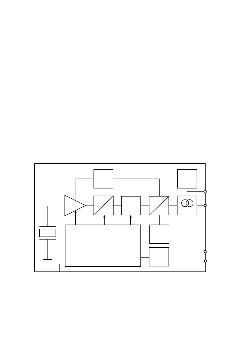
2Function....................................................................................................4
3Type Selection..........................................................................................5
3.1 Frequency Range (HP, LP).................................................................5
3.2 Measuring Range................................................................................6
3.3 Type Code ..........................................................................................6
4Sensor Operation.....................................................................................7
4.1 Sensor Mounting.................................................................................7
4.2 Sensor Connection .............................................................................7
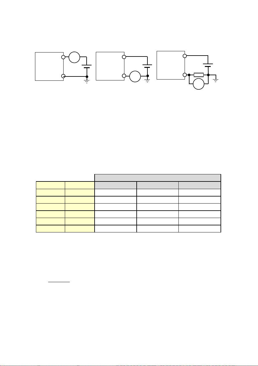
4.2.1 Connection to the Loop Supply..................................................7
4.2.2 Sensor Cable.............................................................................8
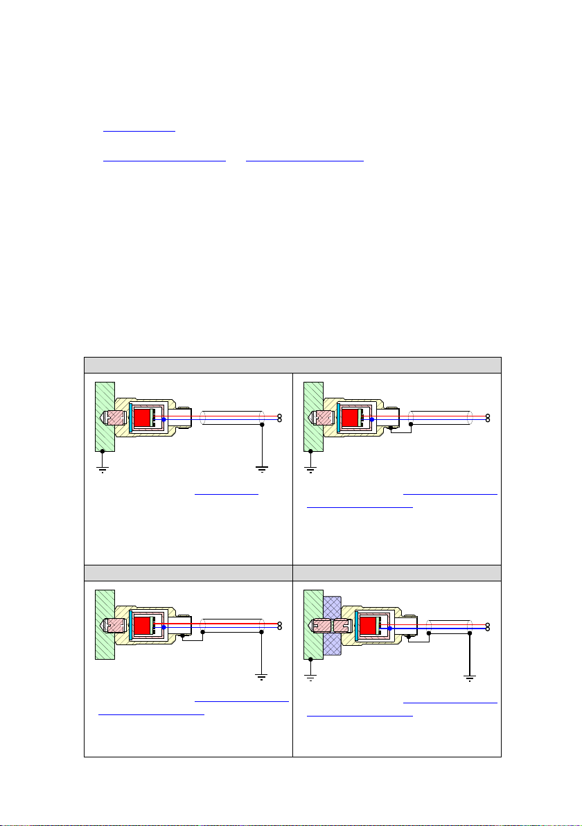
4.2.3 Grounding Concept....................................................................8
4.3 Connection of the Measuring Device..................................................9
4.3.1 Maximum Load Resistance RL...................................................9
4.4 Sensor Self-Test...............................................................................10
4.5 Measuring Mode...............................................................................10
4.5.1 Sensitivity Bi.............................................................................10
4.5.2 Calculation of Acceleration and Velocity..................................10
4.5.3 Offset Current and Noise .........................................................11
4.5.4 Linear Measuring Range xmin…xmax .........................................11
4.5.5 Maximum Dynamic Range.......................................................12
4.6 Overload Display...............................................................................12
4.7 Averaging Filter.................................................................................12
4.7.1 Number of Averages N.............................................................12
4.7.2 Settling Time T.........................................................................13
4.8 Total accuracy...................................................................................13
4.9 Error Messages.................................................................................14
4.9.1 Steps to Fix a LOOP Error.......................................................14
5Technical Data........................................................................................15
5.1 Technical Characteristics of the 4-20mA Signal Conditioning...........15
5.2 Electrical Characteristics...................................................................15
5.3Mechanical Characteristics...............................................................15
5.4 Environmental Characteristics ..........................................................15
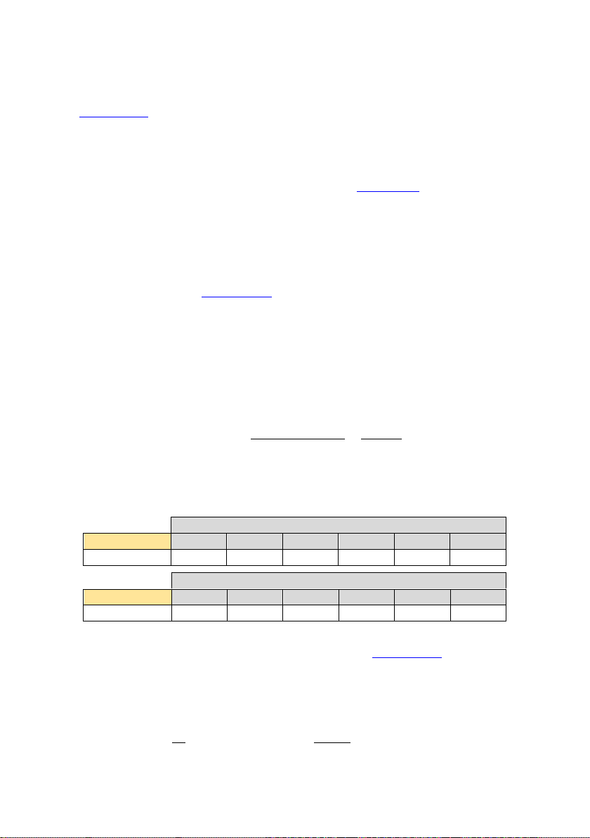
5.5 Type Tables......................................................................................16
5.5.1 Acceleration, RMS ...................................................................16
5.5.2 Acceleration, PEAK..................................................................17
5.5.3 Velocity, RMS ..........................................................................18
5.5.4 Velocity, PEAK.........................................................................18
Limited Warranty........................................................................................19
Declaration of Conformity.........................................................................19

4
1 Purpose
The vibration sensors of the KSI84xx family are used to measure vibration
acceleration or velocity on machines and objects.
The sensors measure the vibration amplitude within a specified frequency range in
axial sensor direction and outputs the measuring result as a 4-20 mA current loop
signal. The sensor is supplied with power via the same signal line.
The sensor parameters are adjustable. There are different types for different appli-
cations in several measuring ranges. The sensors comply with the specifications for
vibration measuring devices according to ISO 2954.
Possible applications are:
1. Measurement of the smooth running of rotating machines and
reciprocating machines according to ISO 10816 / ISO 20816.
2. Measurement of bearing vibrations according to VDI 3832.
3. Measurement of vibrations in defined frequency ranges.
The sensors are suitable for use in harsh environmental conditions. The housing is
double shielded, electrically isolated and complies with protection grade IP68.
2 Function
The sensors of the KSI84xx family are piezoelectric vibration sensors.
A piezoelectric accelerometer is used as the sensor element. Its electrical output
signal is first amplified and digitized.
The signal analysis is digital. The signal is filtered (HP, LP), optionally integrated
and the amplitude value is calculated, either as RMS or PEAK value. Finally, the
amplitude value is converted into a 4-20 mA current loop signal with a 16 bit DAC.
Piezo
GAIN
A
D
D
A
+
-
RXD
TXD
Signal
Analysis
4-20mA
KSI84xx
Parameter Set
- Range
- HP Filter, LP Filter
- Integrator
- RMS/Peak
- Average Filter
Port
ERROR
Detection
OVL
Detection
POWER
Supply

5
Either the acceleration (without integration) or the velocity (with integration) of the
vibration can be measured.
In addition, proper sensor function and input signal are monitored. Defects or
overloads are signaled by an error current value.
Before delivery, the sensor is parameterized according to the type code selected by
the customer.
3 Type Selection
There are four different basic types, which differ in the measured quantity
(acceleration or velocity) and the amplitude mode (RMS or PEAK).
Sensor type
KSI84AR-xx
KSI84AP-xx
KSI84VR-xx
KSI84VP-xx
Quantity
Q
Acceleration
Velocity
Mode
M
RMS
PEAK
RMS
PEAK
Furthermore, the types differ in the measured frequency range (HP, LP) and in their
measuring range.
3.1 Frequency Range (HP, LP)
The used frequency range of a sensor type is described by the values HP and LP in
the type table.
HP is the -3 dB cutoff frequency of the high pass filter and determines the lower
cutoff frequency of the sensor.
LP is the -3 dB cutoff frequency of the low pass filter and determines the upper
cutoff frequency of the sensor.
All frequencies between the lower and upper cutoff frequency have an impact to the
measuring result.
Sensors measuring acceleration have a 2nd order IIR high pass and low pass filter
with a stopband attenuation of -40 dB/decade.
Frequency response

6
The HP filter of velocity sensor types has a stopband attenuation of -50 dB/decade,
the LP filter has a stopband attenuation of - 40 dB/decade.
3.2 Measuring Range
The “Range” value in the type table corresponds to the measured value at which the
sensor current is 20 mA. At this level the sensor output is regarded as 100 %.
The measured value must always be within the linear measuring range. This is the
range from 1 % to 112.5 % referred to 20 mA.
3.3 Type Code
The type code is printed on the sensor housing. It is composed according to the
following key. Note that only integer values without decimal places are printed in
the type code.
Range
in m/s² (2…3 places)
in mm/s (2 places)
Low-Pass filter
-3dB cutoff frequency
(2…3 places)
High-Pass filter
-3dB cutoff frequency
(1…3 places)
Mode
R: RMS
P: Peak
Quantity
A: Acceleration
V: Velocity
KSI84QM-HHH-LLL-RRR
Frequency response

7
4 Sensor Operation
4.1 Sensor Mounting
The choice of an appropriate measuring point on the target is important for accurate
vibration measurement. It can be helpful to consult a specialist in machine moni-
toring for this purpose.
In general, it is advisable to measure vibrations as near as possible to their source.
This minimizes errors by transmitting mechanical components.
Suitable measuring points are rigid components, for instance the housing of bearings
or gearboxes. Not recommended for vibration measurement are lightweight, flexible
and soft components. The standard ISO 10816-1 gives some recommendations for
suitable measuring points.
The KSI84xx is mounted via the M8 threaded hole in the sensor base. The sensor
can either be mounted directly using the M8 mounting stud type 043 or with the help
of the mounting pad type 229 with M8 stud by epoxy cementing on the object.
Alternatively, the senor can also be fixed by the magnetic base type 208 (M8) or
type 008 (M5) in combination with the thread adapter type 044.
The sensor should be in touch with the target by its complete mounting surface.
Rough, scratched or too small measuring points may cause errors. Cast or varnish
surfaces are unsuited.
A thin layer of silicone grease between the mounting surfaces also improves
vibration transmission.
4.2 Sensor Connection
4.2.1 Connection to the Loop Supply
The sensor is connected via PIN 2 (+) and PIN 3 (-) of the output connector to the
loop supply voltage. PIN 1 and PIN 4 are not to be connected.
1: Do not connect
2: + current loop
3: - current loop
4: Do not connect
The loop supply voltage USshould be within 10 to 30 V and free of noise.
It is recommended to select a lower voltage at ambient temperatures above 80 °C in
order to reduce self-heating due to the power dissipation inside the sensor.
- Loop
+ Loop
n.c.
3
2
4
1
View at sensor pins
n.c.

8
4.2.2 Sensor Cable
We recommend to use shielded cable for best EMI protection. The cable shield has
be connected to earth potential at one end (see 4.2.3).
Metra offers the following connection accessory:
Type 080G/W: Binder 713, female, straight (G) or angled (W) with screw
terminals for connection an existing sensor cable; protection grade IP67
Type 082-B713G-PIG-x or type 082-B713G-PIG-x:
Shielded sensor cable, x m length with Binder 713, female, straight (G) or
angled (W) and cable end sleeves; protection grade IP67
Make sure that the cable is not routed alongside AC power lines and in adequate
distance to potential EMI sources. It should cross AC power lines at right angles.
4.2.3 Grounding Concept
The sensor has an outer and an inner housing shield to protect the electronics against
EMI. Both housings are electrically isolated from each other.
The inner shield is connected via PIN3 to the potential of thee negative loop line.
The outer sensor housing is direct connected to ground via the M8 mounting thread
(case 1) or is connected via the cable shield (case 2).
Case 1: Direct grounding
Sensor connection with type 080G/W:
Sensor connector electrically isolated
→ connect shield toground on device
side
Sensor connection with type 082-B713G-PIG-x
or type 082-B713W-PIG-x:
Shield connected to sensor connector
→ Leave shield open on device side
Case 2: potential free mounting
Case 2: Isolated mounting
Sensor connection with type 082-B713G-PIG-x
or type 082-B713W-PIG-x:
→ connect shield toground on device
side
Sensor connection with type 082-B713G-PIG-x
or type 082-B713W-PIG-x:
→ connect shield toground on device
side

9
4.3 Connection of the Measuring Device
The following figures show possibilities to measure the sensor current.
The sensor current can be measured either directly by a current meter connected in
series or indirectly by measuring the voltage drop across the load resistance RL
between PIN 3 and the negative terminal.
Choose the connection shown in the first figure for best EMI protection.
The voltage drop uLacross RLis calculated from the sensor current as follows:
The following table shows the voltage drop uLas a function of the sensor current at
different load resistors RL.
Voltage drop over RL
Excitation
iSensor
125
250
500
0 %
4 mA
0,5 V
1 V
2 V
10 %
5,6 mA
0,7 V
1,4 V
2,8 V
20 %
7,2 mA
0,9 V
1,8 V
3,6 V
50 %
12,0 mA
1,5 V
3 V
6 V
100 %
20,0 mA
2,5 V
5 V
10 V
112,5 %
22,0 mA
2,75 V
5,5 V
11 V
4.3.1 Maximum Load Resistance RL
The maximum load resistance RLdepends on the loop supply voltage US. It results
from the fact that the sensor requires at least 7 V at the highest possible loop current.
The calculation is as follows:
RL: Load resistance of current loop
US: Loop supply voltage in V
It can be seen that the load resistance RLmust not exceed 680 with a supply
voltage US= 24 V.
KSI84xx
+ PIN 2
- PIN 3
A
+
Us
-
KSI84xx
+ PIN 2
+
- PIN 3
A
Us
-
KSI84xx
+ PIN 2
+
Us
-
- PIN 3
RL
-
V

10
4.4 Sensor Self-Test
The sensor starts with a self-test once it is connected to the loop supply voltage.
During self-test, the sensor outputs the maximum sensor current of 22 mA and the
offset current of 4 mA for a duration of 2 seconds. These currents can be measured
with an ampere meter to ensure proper function.
If there is no error, the normal measuring operation starts afterwards, in which the
sensor current corresponds to the current measured value.
If the sensor is not able to output 22 mA, there is a LOOP error. In this case, the
sensor repeats the self-test until the error is fixed.
4.5 Measuring Mode
4.5.1 Sensitivity Bi
In measuring mode, the sensor output current iSensor is proportional to the vibration
amplitude. A constant offset current of 4 mA is overlaid on this current for the
sensor supply.
The proportionality factor Bia or Biv is called sensitivity. The sensitivity depends on
the measuring range of the sensor. It results from the quotient of the current change
at 100 % excitation and the measuring range.
The following table shows the sensitivity of the acceleration and velocity types for
different measuring ranges.
Range
KSI84Ax
10
20
50
100
200
500
Bia / mA/m/s²
1.6
0.8
0.32
0.16
0.08
0.032
Range
KSI84Vx
10
12.7
20
25.4
40
50.8
Biv / mA/mm/s
1.6
1.26
0.8
0.63
0.4
0.315
The sensitivity Bichanges only slightly over temperature due an electronic
compensation. The remaining TC(Bi) can be found in the technical data.
4.5.2 Calculation of Acceleration and Velocity
The acceleration or velocity is determined from the sensor current as follows:

11
4.5.3 Offset Current and Noise
The offset current Ioff of the sensor is 4 mA. This is the zero point in measuring
mode. The calibrated value is output while sensor elf-test for control.
A slightly larger current value is measured when no vibration excitation is present,
the current in rest. This is the smallest output value in measuring mode. It consists of
the offset current and the current of the sensor noise.
The Noise depends on the type and is specified in the type table in m/s² or mm/s.
Multiplication by the sensitivity Bigives:
The offset current Ioff changes only slightly over temperature and time. For details
see in technical data.
4.5.4 Linear Measuring Range xmin…xmax
The current loop sensor is calibrated at two vibration amplitudes to achieve optimum
linearity of the sensor current over the entire measuring range.
The range for valid measurements extends from …
xmin
xmax
Sensor types
(1)
1 % of range
(4.16 mA)
112.5 % of rang
(22 mA)
All types except (2)
(2)
2 % of range
(4.32 mA)
KSI84AP-xx-10k-xxx
Within this measuring range,
the linearity of sensitivity (gain
error) specified in the technical
data is maintained.
If the vibration signal is smaller
than the specified minimum
xmin, the measurement error
increases due to sensor noise
and the limited resolution of the
AD converter.
At vibration amplitudes greater
than the maximum xmax, the sensor current no longer increases. It remains constant
at 22 mA. A sensor with a larger measuring range must be selected.
xmin
100 %
0 %
1 %
-1 %
Deviation
10 %
Vibration signal
Calibration

12
4.5.5 Maximum Dynamic Range
The maximum dynamic range is the maximum peak amplitude value that can be
processed without overdriving the signal processing.
For accelerometers, the maximum dynamic range is independent of frequency.
For all velocity sensors, the maximum dynamic range depends on the frequency. It
is halved when the frequency doubles.
The following table contains the maximum acceptable peak value of the acceleration
or velocity signal for the different measuring ranges.
Range
KSI84AR
10
20
50
100
200
500
a_pk / m/s²
47
47
95
190
380
750
Range
KSI84VR
10
12,7
20
25,4
40
50,8
v_pk / mm/s @160 Hz
93
93
186
186
372
372
v_pk / mm/s @640 Hz
23
23
46
46
93
93
4.6 Overload Display
The sensor outputs 22 mA to indicate an existing overload. The signal component
causing this overload does not have to be in the linear frequency range of the sensor.
It can also be within the stopband of the sensor type.
In case of an overload status, the measurement result is incorrect. The sensor must
be changed against another type with a larger measuring range.
4.7 Averaging Filter
4.7.1 Number of Averages N
The sensor output is updated every 0.5 seconds in RMS mode and once per second
in PEAK mode.
To reduce signal ripple by low frequencies and to improve the signal-to-noise ratio,
the output signal is additionally filtered using a moving average filter. The number
of averages Nis adjustable.
By default, the sensor is delivered with the average filter setting N= auto. In this
mode the number of averages Ndepends on the amplitude mode (rms, peak) and on
the high pass filter setting.
Highpass filter
RMS, auto
PEAK, auto
1.5 Hz / 3 Hz / 10 Hz
N = 8
N = 4
30 Hz / 100 Hz / 1 kHz
N = 4
Optionally, the averaging filter can also be obtained with the settings N = 1, 2, 4, 8.
The setting of the average filter can also be adjusted afterwards.

13
4.7.2 Settling Time T
The averaging filter causes a signal delay. If the vibration signal changes abruptly,
the sensor signal only changes smoothly. The signal change is not completed until
the settling time T has elapsed.
The table below shows the relationship between the number of averages Nand the
minimal settling time T.
N
RMS
PEAK
1
T = 0,5 s
T = 1 s
2
T = 1 s
T = 2 s
4
T = 2 s
T = 4 s
8
T = 4 s
T = 8 s
We recommend to use a short settling time for the use of the sensor in a closed
control loop. Please specify when ordering: N=1 or N=2.
4.8 Total accuracy
All vibration sensors of the KSI84xx family are individually measured and calibrated
before delivery. Calibration is performed both electrically and mechanically in our
certified vibration measurement laboratory.
Systematic errors caused by temperature are largely corrected by signal processing.
The following overview contains the most important error quantities to estimate the
total accuracy of the sensor.
Error quantities
Max
Importance
Basic accuracy of the
nominal range
2
%
Accuracy of the sensor sine calibration (at a
certain amplitude and frequency, at T = 23 °C)
Linearity
2
%
Additional error at any amplitude. The typical
error function is shown in chapter 4.5.4.
The error maximum is at the lower end of the
linear measuring range.
Temperature
%
Additional error at any temperature within the
operating temperature range.
Frequency response
1
%
Additional error due to deviation of sensor
frequency response from ideal frequency response
Basic accuracy of
offset current
1
µA
These errors influence the zero point of the
sensor. They effect to the total error only at
very low vibration levels.
Offset current drift
see 5.1
Noise
see 5.5

14
4.9 Error Messages
If the sensor current is between 4 mA and 22 mA, the sensor is in normal operational
mode.
Any current outside this range indicates a specific error. The following table shows
the values used.
Current
Error
Cause
Remedy
3,75
mA
LOOP
Error
The sensor cannot
output the correct
current value because
the current loop
proper setup
Restart the sensor.
There is a LOOP-Error if the
sensor remains in self-test after
restart.
→follow steps 4.9.1
SENSOR
Error
Die Signalverarbeitung
des Sensors arbeitet
nicht normal.
Restart the sensor.
There is a SENSOR-Error if the
Sensor does not start with the
self-test. The sensor constantly
outputs 3,75 mA.
→Replace sensor
22 mA
Overload
(OVL)
Vibration signal too
high
Use a sensor type with a higher
measuring range.
→Replace sensor
4.9.1 Steps to Fix a LOOP Error
1. Check the value of the load resistance RLand reduce it if possible
2. Check the value of the loop supply voltage and increase it if possible

15
5 Technical Data
5.1 Technical Characteristics of the 4-20mA Signal Conditioning
Sensor system
Piezoelectric accelerometer
Measured quantity
Q
KSI84Ax-x-x-x
KSI84Vx-x-x-x
according to type code
Acceleration
Velocity
m/s²
mm/s
Mode
M
KSI84xR-x-x-x
KSI84xP-x-x-x
according to type code
RMS
PEAK
... pk
Linear frequency range
High pass filter 1) -3dB
Low pass filter 2) -3dB
fHP KSI84xx-HP-x-x
fLP KSI84xx-x-LP-x
according to type code
1.5 / 3 / 10 / 30/ 100 / 1k
100 / 300 / 1 k / 5k / 10k
Hz
Hz
Nominal range1) ±accuracy
xN@20 mA, @23°C
KSI84Ax-x-x-R
KSI84Vx-x-x-R
according to type code
10/20/50/100/200/500 ±2 %
10/12.7/20/25.4/40/50.8 ±2 %
m/s²
mm/s
Linear measuring range
xmin ... xmax
1…112.5 ; (2…112.5) 3)
% of xN
Linearity of sensitivity
(Gain error)
Bix @xmin ... xmax
@23°C
± 2
%
Temperature coefficient of
sensitivity
TC(Bi)
+ 0.015
%/K
Max. offset drift over temp.
Ioff @Tmin...Tmax
± 4
µA
Max. offset drift over time
Ioff @5.000 h
+ 1
µA
Resolution (noise)
see type table
Transverse sensitivity
G90max
< 5
%
5.2 Electrical Characteristics
Current output
IOUT
4…22
mA
Loop supply voltage
US
10…30
V
Settling time 4)
T
< 5
s
Load resistance
RL
< 40 ∙ ( Us - 7 )
Ground insulation
RISO @250 VDC
> 4000
M
Dielectric strength
UISO
350
VDC
5.3 Mechanical Characteristics
Dimensions
Ø/ h
SW22 / 43.1
mm
Weight
m
60 / 2.1
g / oz
Housing material
Stainless steel
Mounting
M8 thread in base
Connector
Binder 713, 4 pole, male
5.4 Environmental Characteristics
Operating temperature
Tmin / Tmax
-40 / 100
°C
Protection grade
IP68
Destruction shock limit
amax
5000
g
EMI
EN 61326-2-3:2013
1) Type code contains only integer values without decimal places
2) The condition LP ≥ 10 HP must be met
3) Restricted linear measuring range for type code KSI84AP-x-10k-x
4) Settling time for average filter= auto, 1...9 s optionally available

16
5.5 Type Tables
5.5.1 Acceleration, RMS
Q
M
HP
Hz
LP
Hz
Range
m/s²
Type code
Noise
m/s²
a
RMS
1.5
100
300
1k
10
KSI84AR-1-LP-10
0.005
20
KSI84AR-1-LP-20
0.005
50
KSI84AR-1-LP-50
0.007
100
KSI84AR-1-LP-100
0.007
200
KSI84AR-1-LP-200
0.008
500
KSI84AR-1-LP-500
0.016
5k
10
KSI84AR-1-5k-10
0.020
20
KSI84AR-1-5k-20
0.020
50
KSI84AR-1-5k-50
0.030
100
KSI84AR-1-5k-100
0.060
200
KSI84AR-1-5k-200
0.080
500
KSI84AR-1-5k-500
0.160
10k
20
KSI84AR-1-10k-20
0.050
50
KSI84AR-1-10k-50
0.090
100
KSI84AR-1-10k-100
0.180
200
KSI84AR-1-10k-200
0.200
500
KSI84AR-1-10k-500
0.250
3
10
30
100
100 1)
300 1)
1k
10
KSI84AR-HP-LP-10
0.005
20
KSI84AR-HP-LP-20
0.005
50
KSI84AR-HP-LP-50
0.007
100
KSI84AR-HP-LP-100
0.007
200
KSI84AR-HP-LP-200
0.008
500
KSI84AR-HP-LP-500
0.016
1k
10k
20
KSI84AR-1k-10k-20
0.050
50
KSI84AR-1k-10k-50
0.090
100
KSI84AR-1k-10k-100
0.180
200
KSI84AR-1k-10k-200
0.200
500
KSI84AR-1k-10k-500
0.250
1) The condition LP ≥ 10 HP must be met

17
5.5.2 Acceleration, PEAK
Q
M
HP
Hz
LP
Hz
Range
m/s² pk
Type code
Noise
m/s² pk
a
Peak
1.5
100
300
1k
10
KSI84AP-1-LP-10
0.005
20
KSI84AP-1-LP-20
0.005
50
KSI84AP-1-LP-50
0.007
100
KSI84AP-1-LP-100
0.007
200
KSI84AP-1-LP-200
0.008
500
KSI84AP-1-LP-500
0.016
5k
10
KSI84AP-1-5k-10
0.020
20
KSI84AP-1-5k-20
0.020
50
KSI84AP-1-5k-50
0.030
100
KSI84AP-1-5k-100
0.060
200
KSI84AP-1-5k-200
0.080
500
KSI84AP-1-5k-500
0.160
10k
50
KSI84AP-1-10k-50
0.090
100
KSI84AP-1-10k-100
0.180
200
KSI84AP-1-10k-200
0.200
500
KSI84AP-1-10k-500
0.250
3
10
30
100
100 1)
300 1)
1k
10
KSI84AP-HP-LP-10
0.005
20
KSI84AP-HP-LP-20
0.005
50
KSI84AP-HP-LP-50
0.007
100
KSI84AP-HP-LP-100
0.007
200
KSI84AP-HP-LP-200
0.008
500
KSI84AP-HP-LP-500
0.016
1k
10k
50
KSI84AP-1k-10k-50
0.090
100
KSI84AP-1k-10k-100
0.180
200
KSI84AP-1k-10k-200
0.200
500
KSI84AP-1k-10k-500
0.250
1) The condition LP ≥ 10 HP must be met

18
5.5.3 Velocity, RMS
Q
M
HP
Hz
LP
Hz
Range
mm/s
Type code
Noise
mm/s
v
RMS
1,5
100
300, 1k
40
KSI84VR-1-LP-40
0.100
50,8
KSI84VR-1-LP-50
3
100
300
1k
20
KSI84VR-3-LP-20
0.035
25.4
KSI84VR-3-LP-25
40
KSI84VR-3-LP-40
50.8
KSI84VR-3-LP-50
10 1)
100
300
1k 1)
10
KSI84VR-10-LP-10
0.010
12.7
KSI84VR-10-LP-12
20
KSI84VR-10-LP-20
25.4
KSI84VR-10-LP-25
40
KSI84VR-10-LP-40
50.8
KSI84VR-10-LP-50
30
300
1k
10
KSI84VR-30-LP-10
0.005
12.7
KSI84VR-30-LP-12
20
KSI84VR-30-LP-20
25.4
KSI84VR-30-LP-25
40
KSI84VR-30-LP-40
50.8
KSI84VR-30-LP-50
1) Complies with the requirements of ISO 2954
5.5.4 Velocity, PEAK
Q
M
HP
Hz
LP
Hz
Range
mm/s pk
Type code
Noise
mm/s pk
v
Peak
10
100
300
1k
20
KSI84VP-10-LP-20
0.010
25.4
KSI84VP-10-LP-25
40
KSI84VP-10-LP-40
50.8
KSI84VP-10-LP-50
30
300
1k
10
KSI84VP-30-LP-10
0.005
12.7
KSI84VP-30-LP-12
20
KSI84VP-30-LP-20
25.4
KSI84VP-30-LP-25
40
KSI84VP-30-LP-40
50.8
KSI84VP-30-LP-50

19
Limited Warranty
Metra warrants for a period of
24 months
that its products will be free from defects in material or workmanship
and shall conform to the specifications current at the time of shipment.
The warranty period starts with the date of invoice.
The customer must provide the dated bill of sale as evidence.
The warranty period ends after 24 months.
Repairs do not extend the warranty period.
This limited warranty covers only defects which arise as a result
of normal use according to the instruction manual.
Metra’s responsibility under this warranty does not apply to any
improper or inadequate maintenance or modification
and operation outside the product’s specifications.
Shipment to Metra will be paid by the customer.
The repaired or replaced product will be sent back at Metra’s expense.
Declaration of Conformity
According to EMC Directive 2014/30/EC
Product: Vibration Sensor
Type: KSI84xx
It is hereby certified that the above mentioned product complies
with the demands pursuant to the following standards:
EN 61326-2-3:2013
EN61000-6-4:2006 + A1:2011
EN61000-6-2:2005
The producer is responsible for this declaration
Manfred Weber Metra Mess- und Frequenztechnik in Radebeul e.K.
Meissner Str. 58, D-01445 Radebeul
declared by:
Michael Weber, Radebeul, July 28, 2020
Other manuals for KSI84 Series
1
This manual suits for next models
4
Table of contents
Other MMF Accessories manuals