Mobility Research LiteGait 300P Series User manual

LiteGait® is a Registered Trademark of Mobility Research, Inc.
Operator & Service Manual
300P Series
300P Standard
300P Deluxe


www.LiteGait.com
1-800-332-9255
SERIAL
NUMBER
Serial Number of Your Device:
Note: Please keep your serial number in a safe and secure location. The serial number must be
provided when seeking service for your LiteGait® device. The serial number provides us access to
technical information regarding your device.


www.LiteGait.com
1-800-332-9255
IMPORTANT SAFETY INSTRUCTIONS
Use only under the direct supervision of a health care profes-
sional or caregiver
Brakes should remain in the locked position at all times until
transfer from one location to another is initiated.
Operate on smooth and level surfaces ONLY.
READ ALL INSTRUCTIONS BEFORE USING LiteGait®
***WARNING***
MAXIMUM PATIENT WEIGHT:
LiteGait®I 300P: 300 lbs
MAXIMUM UNIT HEIGHT:
7 feet 6 inches


7 www.LiteGait.com
1-800-332-9255
Dear LiteGait® User,
CONGRATULATIONS on your recent purchase of LiteGait®, the most innovative gait and balance
therapy training system available today. As you know, LiteGait® can be used with a wide variety of
patient impairment levels and conditions. If you have questions about the possible uses of LiteGait®
with particular patients, or are in need of some ideas for ways to use LiteGait® more effectively,
please do not hesitate to contact us for information relating to your individual situation. Our web-
site also offers valuable information.
Like all quality therapy equipment, LiteGait® requires regular inspections. Enclosed is a check list for
your convenience. Please complete the checklist every 6 months to ensure the efficient, safe, and
effective operation of the LiteGait® unit. If you should find a problem with a LiteGait® part, please
contact the Service & Parts Department immediately. Here are some resources, which will be of
help to you:
WEBSITE: www.LiteGait.com
USER FORUM : www.LiteGait.org
Sincerely,
Customer Service Department
Mobility Research


9 www.LiteGait.com
1-800-332-9255
Table of Contents
Unpacking and Assembly .................................................................................. 10
Unit Diagram ..................................................................................................... 13
About Your Unit................................................................................................. 13
USING Your LiteGait® ......................................................................................... 14
I. Manual Yoke Adjustment ............................................................................. 14
II. Actuated Height Adjustment....................................................................... 14
III FlexAble ...................................................................................................... 14
IV. Control Unit ............................................................................................... 15
V. Charging LiteGait® ....................................................................................... 15
VI. Adjusting Handle Bars................................................................................ 16
VII. Base and Casters....................................................................................... 16
IX. Harness Application ................................................................................... 18
Unit Care and Maintenance .............................................................................. 23
Troubleshooting ................................................................................................ 26
Parts List ........................................................................................................... 28
Resource Directory ............................................................................................ 31

10 www.LiteGait.com
1-800-332-9255
LiteGait® Assembly
Tools Required:
Scissors
1/2 inch socket or open-end wrench
5/16 inch Allen wrench (provided)
LiteGait®I Assembly Instructions:
Read below & follow pictures.
NOTE: Two people are required for safe assembly.
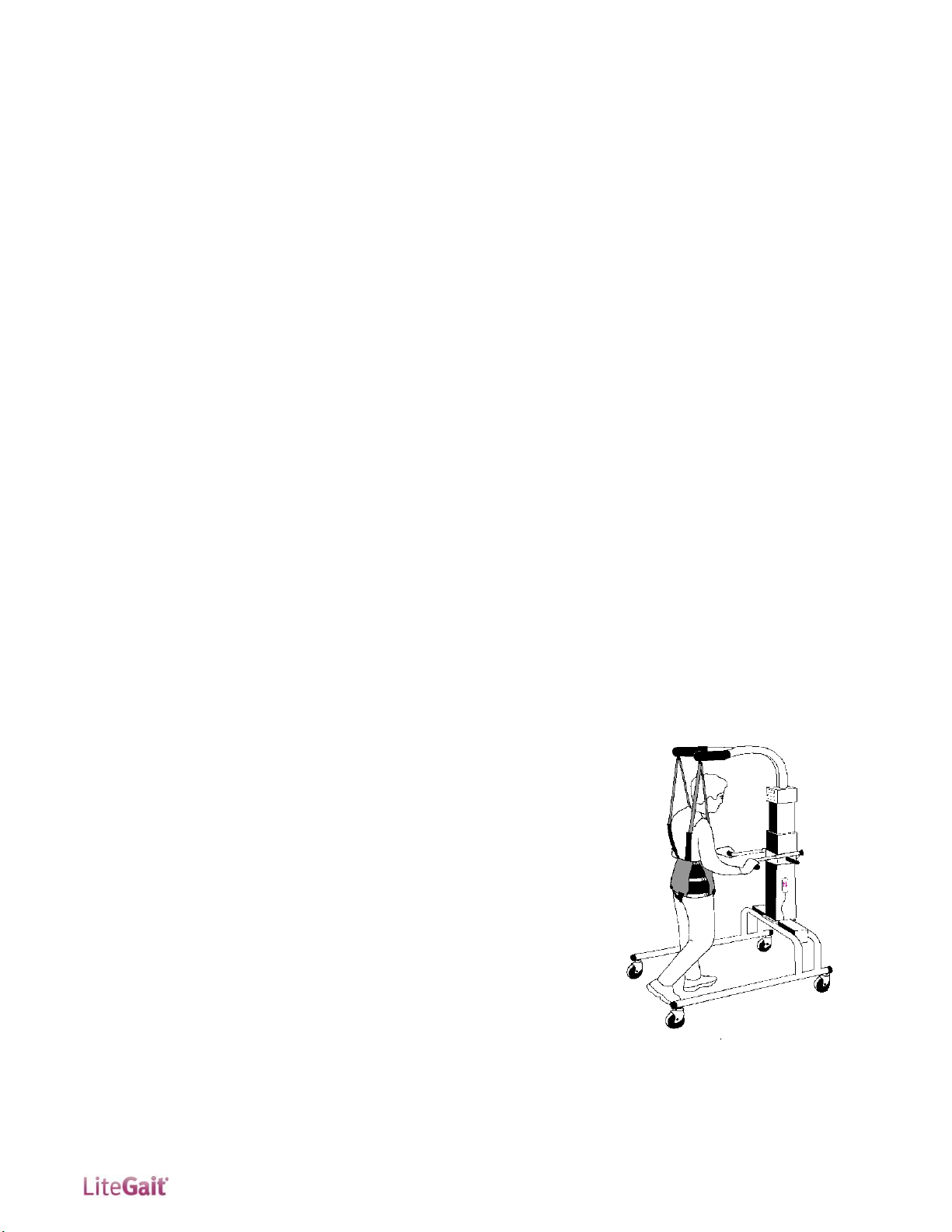
NOTE: Your LiteGait® may look different than the follow-
ing images.
1.) Inspect shipment and note
any visual damage to box and/or
crate.
2.) Remove screw located at the
bottom of crate.
3.) Lift off exterior box in order
to expose equipment.
4.) Loosen handle bar knobs and
raise handle bars.
6.) Inspect contents of card
board box for damage.
7.) Carefully cut all black plastic
straps securing base to pallet.
5.) Remove and open cardboard
harness and accessories box.
10.) Remove actuator bolts us-
ing 5/16” Allen wrench.
NOTE: If you have any questions during installation,
please contact Mobility Research Service & Parts Depart-
ment for assistance.
CAUTION: DO NOT USE UTILITY
KNIFE TO OPEN BOX
7.) Using both people, remove
base from pallet.
9.) Carefully remove all shrink-
wrap from casters.

11 www.LiteGait.com
1-800-332-9255
12) Locate the hand switch and
slightly raise the actuator to al-
low enough access to remove
actuator from pallet.
13.) Locate bolts holding actua-
tor to pallet. Undo bolts with ½
inch socket or wrench, loosen
actuator from pallet with one
person holding the actuator
steady while loose.
14.) Lower handlebar base on
actuator and tighten knobs be-
fore lifting. Ensure base is ready
for positioning actuator. Using
two people lift actuator from
pallet to base.
15.) Orient the actuator on the
base (the yoke arms and handle-
bars point in the same direc-
tion as the base legs). Line up
the holes for bolts to be in-
serted.
11.) Set base over pallet as pic-
tured with actuator next to
base.
16.) Insert bolts, hand tighten
bolts (ensure one person holds
actuator steady until secure).
Tighten bolts using 5/16 inch
Allen wrench until snug (do not
to over tighten).
18.) Remove remaining shrink
wrap from handle bars.
17.) Verify operation by moving
actuator up/down by pressing
the arrows on the hand switch.
If hand switch fails to operate
the actuator, check connections
at top of the actuator.
CAUTION: DO NOT over tighten the
bolts.
CAUTION: DO NOT USE UTILITY
KNIFE TO REMOVE SHRINK WRAP
19.) Remove remaining shrink
wrap from yoke.
20.) Remove remaining shrink
wrap from base.
21.) Verify performance of each
locking and directional casters.
Call Mobility Research Service &
Parts Department at 1-800-332-
9255 Extension 7104 for assis-
tance during this assembly.

12 www.LiteGait.com
1-800-332-9255
This section intentionally left blank.

13 www.LiteGait.com
1-800-332-9255
LiteGait® Diagram
1. EZ Adjust Yoke Assembly
2. Buckle Assembly
3. FlexAble
4. Actuator Column
5. Handle Bar Assembly
6. Battery / Battery Compartment
7. Base/Frame
8. Total Locking Casters
9. Directional Locking Casters
10. Control Box
1
3
4
5
2
6
8
10
9
About Your LiteGait®
NOTE: Your LiteGait® may look different than image above
LiteGait® is comprised of several parts.
YOKE: EZ FlexAble Yoke assembly with EZ Yoke height
adjustment assist. Y-shaped support arm with
FlexAble spring to allow for rigid or flexible support as
needed.
OVERHEAD STRAPS: Four 44” long adjustable straps
with male connectors at one end and padded female
buckles at the opposite end. The male connectors
attach to the yoke buckles and the female buckles
attach to the harness providing postural support for
the patient.
HARNESS/GROIN PIECE: Adjustable wrap with a
buckle closure in the front and three adjustable straps
on each side. The four male connectors at the top of
the harness that attach into the female buckles of the
overhead straps. The four female buckles at the
bottom of the harness allow for the connection of the
groin piece. The H-shaped stitching on the groin piece
denotes the top (or body side) of the piece.
ACTUATOR: The mechanism that raises and lowers
the yoke. The actuator consists of a concentric
expanding and retracting square tower that houses
the DC motors, gearing and the screw mechanism. It
also provides the structural base to which the
adjustable handlebars are attached.
CONTROL UNIT: Junction box mounted in the base
for the battery power, handheld switch and contains
electrical safety protection circuitry. The battery pack
connects to this unit and is also located within a
compartment of the actuator.
HANDLEBARS: Unit has two adjustable handlebars.
The handle bars are attached to the unit using two
knobs on the back of the main column.
BASE: Two horizontal bars connected by two U-
shaped tubes. The base moves freely over ground or
can be locked into place during use over a treadmill.
However, your unit must be locked into place at all
other times.
CASTERS: Four casters are attached to the base. The
two casters on the left side are total locking and the
two casters on the right are directional locking. Be
certain to lock both caster brakes when using the
unit over a treadmill or when connecting the patient
to the unit.
BISYM (Optional): Provides a display of the pounds/
kilograms of support provided by each arm of the
yoke. The load cells that are installed in the yoke
sense the load on the yoke and feed it to the BiSym
Scale for processing and display.
NOTE: Over tightening the knobs may cause damage.
WARNING: NEVER leave patient unattended in the unit.
7

14 www.LiteGait.com
1-800-332-9255
Using Your LiteGait®
FlexAble
FlexAble allows for the rigid yoke to become position
flexible, with up to 5 inches of travel. Thus, you can
maintain the rigid yoke position or make it flexible –
giving the patient the option to experience more of
their balance and weight bearing at their own discre-
tion.
Flexible Support
Loosen the star knob on the bottom of the FlexAble.
The amount of deflection can be varied by the
amount the knob is loosened
Rigid Support
Tighten the star knob completely on the bottom of
the FlexAble
Actuated Height Adjustment
The LiteGait®powered actuator column is raised and
lowered by a hand switch with one up and one
down arrow.
Lowered Raised
Manual Yoke Adjustment
The LiteGait® 200P and 300P yoke utilizes the EZ
Yoke Height Adjustment assembly. To adjust yoke
height support yoke arm assembly and pull out
spring pin. Once spring pin is pulled out, yoke height
should be easily adjusted. Once yoke is at the desired
height align spring pin with closest hole in the back
of the column to secure yoke in position.
NOTE: With the FlexAble or flexible, the LiteGait®
yoke and harness still provide full support to the
LiteGait® User.
NOTE: Your LiteGait®may look different than the images
above.
Raising the Yoke
Verify that LiteGait®has clearance above the yoke.
Depress the button with the up arrow on the hand
switch. Release the button when the yoke is at the
desired height.
Lowering the Yoke
Verify that LiteGait®has clearance below the yoke.
Depress the button with the down arrow on the
hand switch. Release the button when the yoke
lowers to the desired height.
To secure yoke at desired height
ensure that spring pin is inserted
into hole along the back of the
actuator column.
NOTE: Your LiteGait®may look different than the images
above.
Support Yoke Here when
raising or lowering yoke.

15 www.LiteGait.com
1-800-332-9255
Using Your LiteGait®
Control Unit
Control Unit is the part of the LiteGait®that con-
trols the adjustment of the actuator. The control
STOP and Plug Icons box consists of the following
features.
Red ON/OFF Button
Battery Charge Indicator
Emergency Down Button
Red ON/OFF Button
The emergency ON/OFF Button is the ON/OFF
switch for the LiteGait. To turn the device on, ro-
tate the red button clockwise and it should pop
outward. To turn the device off press the red but-
ton down. The device also automatically turns off
when connected to a power outlet
Red ON/OFF Button
The emergency ON/OFF Button is the ON/OFF
switch for the LiteGait. To turn the device on, ro-
tate the red button clockwise and it should pop
outward. To turn the device off press the red but-
ton down. The device also automatically turns off
when connected to a power outlet
ON OFF
Battery Charge Indicator
The Battery Charge Indicator shows the idle charge
on the battery while the device is on. The indicator
displays the charge in 25% increments. 4 solid
black bars indicates a full charge on the battery. A
plug icon appears in the 50% capacity bar when
charge is down to 25%. The LiteGait®should be
charged when the plug icon appears. When the
battery charge is 0% the display will show a STOP
and a Plug icon, this indicates that the device
needs to be charged as soon as possible. When the
device is turned OFF or is connected to an outlet
the display indicates the STOP and Plug Icons.
NOTE: LiteGait®Battery Should be charged overnight AT
LEAST ONCE PER WEEK.
1. Disconnect LiteGait® Smart
PowerTM Battery from
LiteGait® Base
2. Connect standard plug from
LiteGait® Smart PowerTM-
Charger into LiteGait® Smart
PowerTM- Battery
3. Connect LiteGait® Smart
PowerTM- Charger to an
appropriate 110 volt or 220
volt power outlet outlet.
While the battery is charging,
the LiteGait® Smart PowerTM-
Charger LED should be RED.
4. Leave battery on charger
for 6-8 hours or overnight at
least once per week. The time
it takes to recharge the
battery pack depends upon
the health of the battery pack
and how low the battery pack
was before charging began.
5. LiteGait® Smart PowerTM-
Charger will indicate a
completed charge when the
RED LED changes to GREEN
6. Upon Completion of char
ing, reconnect battery into
LiteGait® and disconnect
LiteGait® Smart PowerTM-
Charger from power outlet.
Charging LiteGait
LiteGait® is equipped with a 24 volt battery pack
that needs to be charged on a weekly schedule. To
recharge your battery follow the steps below. The
battery and charging cord are located in the com-
partment on the left of the actuator

16 www.LiteGait.com
1-800-332-9255
Press tab to lock Locked Caster
Adjusting Handle Bar Configuration
WARNING: LiteGait® Handle Bars are designed to be used
as a balance aid while using the LiteGait. Excess loading
of the handle bars may damage handle bars. Avoid Hav-
ing patients lift their weigh using the handle bars.
Base and Casters
LiteGait® is equipped with four casters. There are
two total locking casters and two directional lock
casters. Each leg has one type of casters, the total
locking are mounted on the left leg the directional
locking are mounted on the right leg.
Directional Lock
Total Lock
The handle bars are designed to be use for balance
while using the LiteGait®. To adjust the height of the
handle bars loosen each knob in equal portions. The
knobs should only need to be turned once to free the
handle bars. Once the knobs are loose, slide the
handle bars to the desired height. Hand tighten both
knobs equally. The knobs should only need to be
tightened until snug. Over tightening of the knobs
may damage the handle bars.
Adjusting Handle Bar Configuration:
The handle bar configuration can be modified to suit
multiple training scenarios while using the LiteGait .
To adjust the configuration,
perform the following steps. Press
the button on the quick release
handle bar pin and pull outward.
Adjust handle bar insert to desired
length and orientation. Press the
button on the quick release handle
bar pin and insert handle bar pin.
The pin can be inserted vertically
and horizontally.
Using Your LiteGait®
Locking and Unlocking Casters
Total Locking Casters
Total locking casters are indicated by a red
sticker on the locking lever. To lock the total
locking casters, press the tab until the brake snaps
into place. The caster will lock the swivel of the
caster and rotation of the wheel. Locking all four
casters will make the device stationary.
Directional Locking Casters
Directional lock casters are indicated by a green
sticker in the locking lever. To lock the
directional locking casters, press the tab and align
the caster with the frame. Once Aligned this locks
the swivel of the casters and is beneficial for
walking in a straight path or placing LiteGait® over
a treadmill. Once the unit is positioned over a
treadmill, all four caster brakes need to be locked
Directional Locking Casters with Treadmill
Position LiteGait® near the treadmill (or where
you wish the patient to begin walking).
Roll LiteGait® towards the front of the
treadmill, until the casters line up parallel
to the treadmill (or parallel to the path the
patient will follow—a hallway for
example).
Press the directional locks to lock swivel of
casters
LiteGait® can now be easily rolled back and forth
over the treadmill or on a straight path in the
therapy room or hallway.
NOTE: While locking the caster prevents rolling of the
unit, it DOES NOT prevent the unit from sliding on a
sloped, slippery floor. The unit should only be used on a
flat floor away from stairs or ramps. NEVER leave a pa-
tient unattended in the unit.
BRAKE
STEER

17 www.LiteGait.com
1-800-332-9255
Using Your LiteGait®
Page Intentionally Left Blank

18 www.LiteGait.com
1-800-332-9255
Harness Application
The harness was designed to support a patient in an upright position, allowing for full hip extension. This
upright posture plays a critical role in the effectiveness of the gait therapy performed with partial weight
bearing.
Using Your LiteGait®
Harness Components
The front of the harness wrap refers to the point at which the two ends of the harness meet. The harness can
be worn with the closure either in the front or in the back. There are four buckles on the top and bottom of
the harness wrap. The four top buckles extend beyond the harness from the top seam and attach to the
LiteGait® overhead straps. The bottom four buckles attach to the groin piece and do not extend past the
bottom seam of the harness.
Preparing Harness for Application
1. Pick the appropriate harness (based on patient’s girth) and groin piece (based on patient’s anterior-
posterior diameter) for the patient.
2. Adjust the groin strap buckles so there is symmetry in the straps-- equal strap length available on both
ends of the padded groin piece and equal from side to side.
3. Attach the groin piece to the back of the harness.
NOTE: The side of the groin piece with the H‐outline stitching (most
padded) will go against the patient’s body.
Front
Overhead Straps
Groin Pieces
Girth Adjustment
Estimating the Starting Size
Half the Girth Test
1. Estimate the harness girth before placing on the patient by folding the
unbuckled harness in half so that the ends meet.
2. Hold the folded harness in front of the patients torso to estimate the width
from one side of the body to the other.
3. Tighten or loosen the three rows of side straps on each side of the harness to
estimated girth.
Symmetry Test
1. With the unbuckled harness folded in half, check the alignment of the top
buckles (the ones that attach to the overhead straps of LiteGait). The buckles
should line up / be adjacent to each other . If not adjacent , make small
adjustment to side straps as needed to regain symmetry. Each side strap should
be similarly lengthened to achieve symmetry.

19 www.LiteGait.com
1-800-332-9255
Using Your LiteGait®
2
3
1
Harness Application - While Standing
1. Wrap harness around patient with lowest side straps even with GREATER
TROCHANTER.
2. Connect buckles top to bottom.
3. Adjust side straps* to the patient from bottom to top, alternate sides and
tighten evenly. Be sure to maintain harness position at Greater
Trochanter.
* To Tighten, push slack of strap towards buckle, while pulling free end as
shown. Do not tighten top buckles over rib cage.
Quick Check
2 fingers should NOT fit between strap and body.
Bulges of tissue may be present between girth adjustment straps if
adjusted appropriately.
NOTE: A loose harness will ride up when overhead support is applied. This will
cause discomfort in the groin region. A snug harness with no slack will grab the
pelvic girdle and hold in place distributing weight evenly throughout harness
wrap.
Attaching Groin Pieces
1. Route the groin piece between legs to front.
2. Connect both buckles - one on each side.
3. Tighten the groin strap snugly so there is NO slack.
To tighten, grab the groin strap or strap cover and:
i. Pull out toward adductor surface of leg.
ii. Pull up toward groin piece buckle.
iii. Use other hand to pull down on excess strap on free end, then
repeat on other leg.
iv. Tighten back straps in the same fashion to remove all slack.
Quick Check
Groin Piece should have NO Slack. Padding should be equal front
and back. Padding should cover most of the inner leg with little or
no exposed strap.
Pull on top buckles, if harness moves up torso, straps require
additional adjustment.
BACK
FRONT
ii
iii
i
iv
NOTE: A LOOSE GROIN PIECE DOES NOT IMPART GREATER COMFORT TO THE PATIENT, BUT AL-
LOWS THE HARNESS TO SLIDE UP THE TRUNK, PUTTING UNWANTED LOAD/FORCE ON THE GROIN
AREA. TIGHTEN THE GROIN STRAP SO THAT NO SLACK REMAINS IN THE STRAPS. THIS ASSURES
THAT THE HARNESS WILL NOT RIDE UP ON THE PATIENT.

20 www.LiteGait.com
1-800-332-9255
CAUTION: SITTING WHILE IN THE LEG STRAPS WILL DISPLACE THE HIP AXIS OF
LOCATION AWAY FROM AND OUT OF THE LEG STRAPS; REPOSITIONING OF THE
LEG STRAPS WILL BE NECESSARY.
Leg Strap Application
1. Wrap Velcro thigh cuff portion below bulk of thigh and above knee so strap
does not interfere with knee function.
2. Strap should be perpendicular to ground and pointing up toward the hip on
the outside of leg.
3. Connect male buckles on leg straps into plastic groin piece female buckles.
4. Tighten all three straps keeping center strap perpendicular to the ground
and on the lateral surface of the leg. The bifurcation point on the strap
(where the strap splits into two) needs to be at the hip joint axis of rotation
to maintain symmetry.
5. Straps must be tightened completely, using a two-handed technique and
getting rid of all slack, to properly anchor the harness in place and properly
transfer the support to the thighs.
Harness Application –In Supine
1. Roll patient away from you.
2. Attach groin piece and place harness on patient with half of the harness
rolled and under patient. (Figure 1)
3. Hold harness in place with lowest strap at greater trochanter
4. Roll patient into supine.
5. Pull harness around.
6. Straighten harness. Reach behind patient to feel back buckle position. Check
for symmetry. (Figure 2)
7. Connect front buckles
8. Tighten all 6 side straps with leg straight. (Figure 3)
9. Connect the groin piece to the front buckles and tighten as in previous
section. (Figure 4)
10. Roll patient away from you
11. Tighten back straps of groin piece, removing all slack. (Figure 5)
Quick Check
Harness should be equally spaced from side to side
Figure 2
Figure 4
Figure 5
Figure 1
Using Your LiteGait®
Figure 3
This manual suits for next models
2
Table of contents