MOBILUS MOTOR mob.iq [RHM] User manual

MOBILUS MOTOR Spółka z o.o.
ul. Miętowa 37, 61-680 Poznań, PL
tel. +48 61 825 81 11, fax +48 61 825 80 52
VAT NO. PL9721078008
www.mob-iq.eu
User manual of mob.iq [ RHM] controllers.
Wersja 1.4ENG, 180327

1. GENERAL INFORMATION
The mob.iq [RHM] remote control is a multi-channel controller designed for remote control
of accessories compatible with the Z-Wave standard (e.g. tubular motors, chain motors,
gate drives, ON / OFF switches, etc.). The controller allows you to control up to 12 groups
of devices with the same or similar functionality - 12 devices max. in a group. The mob.iq
[RHM] remote control is able to operate up to 144 devices.
The remote can work as:
• PRIMARY master controller, can add and remove devices from the Z-Wave network
• SECONDARY second controller, cannot add or remove devices from the Z-Wave network,
works only to control devices. There can be many secondary remotes in the network.
There can only be one PRIMARY controller in one Z-Wave network. Each subsequent control-
ler is added to the network automatically as SECONDARY.
Remote control mob.iq [RHM] - is a remote control with a mechanical keyboard.
2. DESCRIPTION OF THE REMOTE CONTROL
2
1
3
P2P1
4
1Display - channels / status.
2 Ring of 4 information LED’s.
3 Flap housing.
4 Battery compartment 2 x AAA.
P2 Programming button.
Control button / navigation area LEFT.
Control button / navigation area RIGHT.
Control button / navigation area UP.
Control button / navigation area DOWN.
Control button / navigation area STOP.
2

3. CONTENTS OF THE PACKAGE
The packaging contains the following items:
• remote mob.iq [ RHM ]
• 2 AAA batteries in the remote control protected against discharging with a seal,
• user manual,
• wall holder with magnet and fixing pins (2 pcs.).
4. TECHNICAL PARAMETERS
• Radio protocol: Z-Wave
• Frequency:EU 868,42[MHz]
• The supply voltage 3,0 V DC .
• Power source: batteries 2 x AAA LR03.
• Working temperature [ oC ]: 0-40oC.
• Display: LED segment.
• Range in building: 20 [m]. The range of the radio signal depends on the type of con-
struction, used materials and placement of units. The transmition of the radio signal in
different conditions is as follows: brick wall 60-90%, reinforced concrete 2,060%, wooden
structures with sheets of plasterboard 80-95%, glass 80-90%, metal walls 0-10%.
• Dimensions of the remote control (without the handle): 49 x 16 x 125 mm.
3

5. ASSEMBLY OF A HOLDING FIXTURE
Wall mount components:
• transparent handle - A,
• assembling screws cap - B,
• anchors with screws - C.
1. Determine the position where the handle
will be located (easy access, no running
power cables, pipes, reinforcement of
walls, etc.).
2. Determine the points on the wall so that
the handle after assembly will adhere to
the wall and will be mounted perpendi-
cular to the ground.
B
A
C
3. Drill the holes and place the assembly anchors (distance between the holes 36 mm,
diameter 3.5 mm).
4. Attach the handle and tighten it to the wall.
5. Insert the adapter plate.
6. POWER SUPPLY
The device is powered by two batteries AAA
LR03. In the case of low battery level the display
shows information Lo. To change the battery
slide the bottom flap down tight.
+ -
7. THE INITIAL COMMISSIONING
The device is factory protected against battery
wearing. To the deprotecion:
1. Open the battery cover.
2. Remove the seal Z, which protects the
batteries from discharging (marked
in white).
Z
8. CONTROL
CONTROL MODES
A SHORT press of the control button (below 0.5s) causes the action to end position.
A LONG press of the control button (longer than 0.5s) causes the action until the button
is released.
Pressing the STOP button stops the action.
4

CONTINUED 8. CONTROL
Controlling devices in the mob.iq [RHM] remote control consists in controlling a selected
group of devices. If we want to control devices independently, they should be assigned to
separate groups.
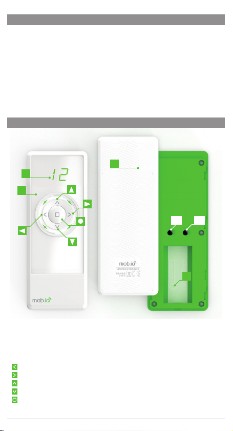
Select the group you want to control with the / buttons (active groups only).
Use the / buttons to control the device or devices.
Press the to stop te action.
9. MENU
In order for the mob.iq [RHM] remote control to control the executive device, it must be
properly configured in the Z-Wave network. The appropriate procedures called on the
controller are used for this. In order to start the corresponding function, hold down the
buttons for 3 seconds:
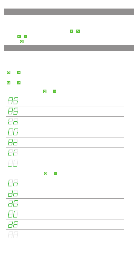
and [FUNCTION SET - MENU I]
or buttons:
and [FUNCTION SET - MENU IO]
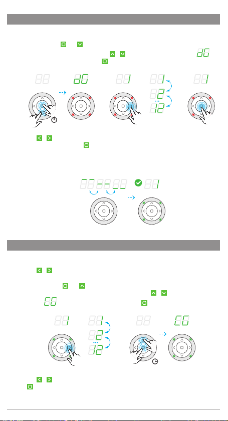
FUNCTION SET - MENU I ( and )
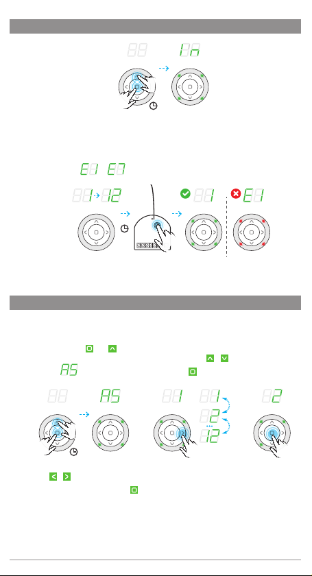
QUICK START - Adds devices to both the network and the group.
ASSOCIATE / ADDING A DEVICE TO A GROUP.
INCLUDE / ADDING A DEVICE TO THE NETWORK.
COPY GROUP - Copies groups to other remotes in the same network.
ASSIGN A ROUTE - The control signal is sent between paired devices.
LISTENING MODE - It allows remote configuration of the remote
control from another remote control.
Returns to the previous screen.
FUNCTION SET - MENU II ( and )
LEARN MODE - Allows you to add a mob.iq [RHM] remote control to
the network as a secondary remote.
DELETE NODE /REMOVING THE DEVICE FROM THE GROUP.
DELETE GROUP - Deletes the entire selected group.
EXCLUDE / REMOVING A DEVICE TO THE NETWORK.
DEFAULT - Resets the remote control settings and removes device
and network information from it.
Returns to the previous screen.
5

6
10. QUICK START
The function allows you to add a device to the Z-Wave network, with simultaneous
assignment to the selected group.
1. Press and hold the and buttons for 3 seconds. The remote will enter the
configuration mode, four green LEDs will light up. Use the / buttons to select the
command - QUICK START
and confirm with the button- Fig.10.1.
Fig.10.1 3 sek.
b
Fig.10.2 Fig.10.3
2. Use the / buttons to select the appropriate group: 1 .. 12, to which you want to assign the
device - Fig.10.2.
3. Confirm the selected group with the button- Fig.10.3.
4. Starting the procedure is signaled on the display by a countdown of 12 seconds.
During this time, press the programming button P on the device. The correct end of the proce-
dure will be signaled on the remote control by blinking of four green LEDs. The error is
signaled by three flashes of four red LEDs and the error number:
to . - Fig.10.4.
Fig.10.4
12 s
If you want to program the next device, perform the above sequence again.
11. ADD DEVICE TO THE NETWORK - INCLUDE FUNCTION
You can add the device to the Z-Wave network at any time without adding it to the group
of devices in the remote control. The INCLUDE function is used for this purpose. Adding the
device to the Z-Wave network means that it is assigned an individual NodeID number in
the Z-Wave network. After adding the device to the network, you must add the device to
the group. This function is only available for the PRIMARY remote control. The INCLUDE
function also allows you to add additional SECONDARY sub remote controls
1. Press and hold the and buttons for 3 seconds. The remote will enter the
configuration mode, four green LEDs will light up. Use the / buttons to select the
command - INCLUDE and confirm with the button - Fig.11.1.

7
CONTINUED. 11. ADD DEVICE TO THE NETWORK - INCLUDE FUNCTION
Fig.11.1 3 sek.
2. Starting the procedure is signaled on the display by a countdown of 12 seconds. During
this time, press the programming button P on the device. The correct end of the procedu-
re will be signaled on the remote control by the lighting of the channel number and the
blinking of four green LEDs. The error is signaled by three flashes of four red LEDs and
the error number: to . - Fig.9.5.
Fig.10.4
12 s
If you are adding another remote control instead of a device, start the REMOTE AS REMOTE
AS SECONDARY function on it.
12. ASSIGNING THE DEVICE TO THE GROUP - ASSOCIATE FUNCTION
This function allows you to add a device to up to 12 groups. You can add up to 12 devices
to each group. Only devices that have already been added to the network can be added to
the group. The group will become active when it is added to it device.
1. Press and hold the and buttons for 3 seconds. The remote will enter the
configuration mode, four green LEDs will light up. Use the / buttons to select the
command - ASSOCIATE and confirm with the button - Fig.12.1.
Fig.12.1 3 sek. Fig.12.2 Fig.12.3
2. Ude the / buttons to select the appropriate group: 1 .. 12 - Fig.12.2.
3. Confirm your selection by pressing the button - Fig.12.3.

CONTINUED12. ASSIGNING THE DEVICE TO THE GROUP - ASSOCIATE FUNCTION
4. Starting the procedure is signaled on the display by a countdown of 12 seconds. During
this time, press the programming button P on the device. The correct end of the procedure
will be signaled on the remote control by blinking of four green LEDs. The error is signaled
by three flashes of four red LEDs and the error number:
to . - Fig.12.4.
Fig.12.4
12 s
13. REMOVING THE DEVICE FROM THE GROUP - THE DELETE FUNCTION
This function allows you to remove a device from the group without removing it from the
Z-Wave network. The device can be added back to the group of any remote control in the
same network.
1. Use the / buttons to select the appropriate group: 1 .. 12 from which you want to
remove the device - Fig.13.1.
2. Press and hold the and button for 3 seconds. The remote will enter the configuration
mode, four red LEDs will light up. Use the / buttons to select the command
- DELETE and confirm with the button - Fig.13.2.
Fig.13.1 Fig.13.2 3 sek.
b
3. Starting the procedure is signaled on the display by a countdown of 12 seconds. During
this time, press the programming button P on the device. The correct end of the procedure
will be signaled on the remote control by blinking of four green LEDs. The error is signaled
by three flashes of four red LEDs and the error number:
to . - Fig.13.3.
Fig.13.3
12 s
8

14. DELETE THE ENTIRE GROUP - DELETE GROUP FUNCTION
Funkcja pozwala usunąć całą grupę urządzeń. Sterowanie urządzeniami jest możliwe dopiero
po ich ponownym dodaniu do grupy.
1. Press and hold the and button for 3 seconds. The remote will enter the configuration
mode, four red LEDs will light up. Use the / buttons to select the command -
DELETE GROUP and confirm with the button - Fig.14.1.
Fig.14.1 3 sek.
b
Fig.14.2 Fig.14.3
2. Use the / buttons to select the appropriate group: 1 .. 12 , you want to delete -
Fig.14.2, and confirm with the button - Fig.14.3.
3. Starting the procedure on the display is signaled by two horizontal lines moving cyclically.
The correct end of the procedure will be signaled on the remote control by blinking of four
green LEDs - Fig.14.4.
Fig.14.4
15. COPYING THE GROUP - COPY GROUP FUNCTION
This function allows you to copy the entire group to another remote control located in the same
network.
1. Use the / buttons to select the appropriate group: 1 .. 12 , which you want to copy
- Fig.15.1.
2. Press and hold the and buttons for 3 seconds. The remote will enter the
configuration mode, four green LEDs will light up. Use the / buttons to select the
command - COPY GROUP and confirm with the button - Fig.15.2
Fig.15.1 Fig.15.2 3 sek.
3. Use the / buttons to select the appropriate group: 1 .. 12 - Fig.15.3and confirm with
the button - Fig.15.4.
9

CONTINUED 15. COPYING THE GROUP - COPY GROUP FUNCTION
rys.15.3 rys.15.4
4. Starting the procedure is signaled on the display by a countdown of 12 seconds. - fig. 15.5.
During this time, activate the LISTENING MODE on the target remote control. The correct end of
the procedure will be signaled on the remote control by blinking of four green LEDs. The error is
signaled by three flashes of four red LEDs and the error number:
to - Fig.15.6.
Fig.15.5
12 s
Fig.15.6
16. REMOVING THE DEVICE FROM THE NETWORK - EXCLUDE FUNCTION
Devices can be removed from the network by MASTER remotes.
1. Press and hold the and button for 3 seconds. The remote will enter the configuration
mode, four red LEDs will light up. Use the / buttons to select the command
- EXCLUDE and confirm with the button - Fig.16.1.
Fig.16.1 3 sek.
b
2. Starting the procedure is signaled on the display by a countdown of 12 seconds. During this
time, press the programming button P on the device. Correct completion of the procedure will be
indicated by four green LEDs flashing. The error is signaled by three flashes of four red LEDs and
the error number:
to - Fig.16.2.
Fig.16.2
12 s
10

17. ASSIGNING THE REMOTE AS A SECONDARY - LEARN FUNCTION
This function allows you to assign a mob.iq [RHM] remote control to an existing Z-Wave
network as a SECONDARY. The MASTER pilot in this network can be of any type. In order for a
SECONDARY remote control to be able to control devices, they must be added to the selected
remote control group.
1. On the SECONDARY remote control, press and hold and the button for 3 seconds.
The SECONDARY remote control will enter the configuration mode, four red LEDs will light
up. Use the / buttons to select the command - LEARN and confirm with the
button - Fig.17.1.
Fig.17.1 3 sek.
b
2. Starting the procedure is signaled on the display by a countdown of 12 seconds - Fig.
17.2. During this time, in the MASTER remote control, start the ADD DEVICE TO THE
NETWORK function. The correct end of the procedure will be signaled on the SECONDARY
remote control by blinking of four green LEDs. The error is signaled by three flashes of four
red LEDs and the error number: to - Fig.17.3.
Fig.17.2
12 s
Fig.17.3
12 s
18. PAIRING DEVICES
This function allows the configuration of devices in one Z-Wave network so that the controlled
device will start another device. For example, a window having a rain sensor may send a
closure signal to other windows when rain is detected. Check in the manuals of the devices to
be linked that the function is available.
1. Press and hold the and buttons for 3 seconds. The remote will enter the
configuration mode, four green LEDs will light up. Use the / buttons to select the
command - ASSOCIATE - Fig.18.1 and confirm with the button.
Fig.18.1 3 sek.
11

CONTINUED 18. PAIRING DEVICES
2. Use the / buttons to select the device pairing group: 1..99 - Fig.18.2 and confirm with
the button - Fig.18.3.
Fig.18.2
99 s 99 s
Fig.18.3
99 s 99 s
3. Within 99 seconds, enter the device to be controlled by another device in PROGRAMMING
MODE - two green LEDs on the remote control will light up and the countdown from 99 s
to 1 s will start - Fig.18.4.
Fig.18.4
99 s 99 s
Fig.18.5
99 s
99 s
Fig.18.6
12 s
4. Within 99 seconds enter the device which is to control another device in the PROGRAM-
MING MODE - two red LEDs on the remote control will light up and the countdown from
99 s to 1 s will start - Fig.18.5.
5. The correct end of the procedure will be signaled on the remote control by blinking of four
green LEDs. The error is signaled by three flashes of four red LEDs and the error number:
to - Fig.18.6.
19. REMOTE RESET
RESETTING THE MASTER REMOTE - deletes all information about the network, groups, etc. Device
control is only possible after removing all devices and adding them again.
RESETTING THE SECONDARY REMOTE- deletes all information. Controlling devices is only possible after
reassigning the secondary remote control to the network and adding the devices to groups.
1. Press and hold the and button for 3 seconds. The remote will enter the configuration
mode, four red LEDs will light up. Use the / buttons to select the command
- default and confirm with the button - Fig.19.1.
Fig.19.1 3 sek.
b
Fig.19.2
12 s
2. The correct end of the procedure will be signaled on the remote control by blinking of four
green LEDs - Fig.19.2.
12

20. LISTENING MODE - REMOTE CONFIGURATION - LISTENING MODE FUNCTION
The remote control entered into the listening state allows remote configuration from another
controller, for example Gateway Z-Wave. Trigger the transfer function.
1. Press and hold the and buttons for 3 seconds. The remote will enter the
configuration mode, four green LEDs will light up. Use the / buttons to select the
command - LISTENING MODE - Fig.20.1 and confirm with the button .
Fig.20.1 3 sek.
2. The controller goes into the LISTENING MODE. The remote control remains in listening mode
for about 30 - 40 s - the green LEDs blink in clockwise order - Fig.20.2.
Fig.20.2
40 sek.
21. ADDITIONAL INFORMATION
PROGRAMMING MODE - programming mode is achieved by pressing the programming button
on the added / removed device. Most often marked with the letter P.
TRANSMISSION FUNCTION - the function is available only in remote controls with the option of
allowing remote transmission of changes in the settings in the listening remote. Each of this type
the remote control may have a separate name for this function.
No range, no programming button pressed.
Low battery of remote control.
Automatic exit from the menu.
Aborting the procedure ( button).
The group to which we want to add the device is full.
You cannot check the battery level if there are more than one device in
the group. The device has no battery.
The group is empty.
WARNING STATUS: low battery when pressed
any button, i.e. after waking up the remote control, the symbol is lit.
for 2 seconds. The device can still be controlled.
CRITICAL STATE: critically low battery level, symbol is on
for 2 seconds, additionally the red backlight blinks quickly for 2
seconds. The device cannot be controlled.
13

14
22. CHANGE OF SOLAR DEVICE PARAMETERS
BASIC PARAMETERS
Hold the button for 3 s. The first set of parameters will appear. Use the / buttons to select
the parameter, enter with the button, use the / buttons to change the parameter values.
Setting the time after which the awning will work in semi-automatic
and automatic mode in the range of 3-10 min.
Setting the sun sensitivity of the awning in semi-automatic and
automatic mode, in the range of 1-99.
- Change of operating mode
A0 - Manual / A1 - Semi-automatic / A2 - Automatic.
ADVANCED PARAMETERS
Hold the button for 6 s. The second set of parameters will appear. Use the / buttons to select
the parameter, enter with the button, use the / buttons to change the parameter values.
Inquiry about the battery level (if the device has one).
Parameter change / Query parameter value.
Changing the parameter value.
To change the parameter value, first select the CP parameter, and then use / buttons
to change the Cd parameter value option. After selecting the desired value, confirm with
button.
23. PROBLEMS ENCOUNTERED
1. The device cannot be added to the Z-Wave network.
CAUSE SOLUTION
The device is added to another Z-Wave
network.
REMOVING THE DEVICE FROM THE
NETWORK.
No programming button pressed. Press the programming button for 2 s.
Too long waiting time for pressing the
programming button on the device.
Press the programming button within 12
seconds.
The controller is assigned to the network as
SECONDARY.
Only MASTER controllers can add or remove
devices.
2. The device cannot be added to the selected group.
CAUSE SOLUTION
The group is full (dot next to the group
number, e.g. ‚1.’). Add the device to another group.
No programming button pressed. Press the programming button for 2 s.
Too long waiting time for pressing the
programming button on the device.
Press the programming button within 12
seconds.

15
23. PROBLEMS ENCOUNTERED
3. The device cannot be removed from the group.
CAUSE SOLUTION
No programming button pressed. Press the programming button for 2 s.
Too long waiting time for pressing the
programming button on the device.
Press the programming button within 12
seconds.
4. Unable to copy group.
CAUSE SOLUTION
Waiting too long to start the LEARNING
MODE function on the target controller.
Start the LEARNING MODE function
in the target controller in time
not longer than 12 seconds.
5. The device cannot be removed from the network.
CAUSE SOLUTION
No programming button pressed. Press the programming button for 2 s.
Too long waiting time for pressing the
programming button on the device.
Press the programming button within 12
seconds.
The controller is assigned to the network as
SECONDARY.
Only MASTER controllers can add and
remove devices.
6. Unable to add mob.iq [RHM] as a SECONDARY.
CAUSE SOLUTION
The controller being added is assigned to
another Z-Wave network.
Restore the controller added to the factory
settings.
Too long waiting time for starting the ADD
DEVICE function on the MASTER controller.
Run the ADD DEVICE function in the
MASTER controller in no more than 12
seconds.
7. Unable to pair devices.
CAUSE SOLUTION
The devices have been paired in reverse
order.
Retry the procedure in the correct order of
adding devices.
Too long waiting time for pressing the
programming button on the device.
Press the programming button within 99
seconds.
8. Range problem.
CAUSE SOLUTION
The distance between devices is too large or
missing power.
Check if the device you want to control is
properly connected to the power source. This
can be done using the manual control button.

16
WARRANTY
The manufacturer guarantees correct device functioning. The manufacturer also agree to repair or
replace device damaged if the damage results from defects in materials and construction.
The warranty is valid for 24 months from the date of purchase under the following conditions:
• Installation was made by a person authorized in accordance with the manufacturer’s instructions.
• Seals haven’t been breached and unauthorized design changes haven’t been made.
• The device was operated as intended by the user manual.
• Damage is not a result of the improperly performed electrical installation or any atmospheric
phenomena.
• The manufacturer is not responsible for damage resulting from misuse or mechanical
damage.
• In case of failure the device should be provided for repair with proof of purchase.
Defects found during the warranty period will be removed free for no longer than 14 working days
from the date of acceptance of device for repair. The manufacturer MOBILUS MOTOR Sp. z o.o.
carries on warranty repairs repairs. If you have any questions, please contact your dealer (please
provide the following information: event description, description of the error, the conditions under
which the accident occurred).
MAINTENANCE
1. For cleaning, use a soft cloth (eg. microfiber), moistened with water. Then wipe dry.
2. Do not use chemicals.
3. Avoid using in soiled and dusty environments.
4. Do not use the device at temperatures higher or lower than the declared range.
5. Do not open the device - otherwise the warranty shall be lost.
6. The device is sensitive to dropping, throwing.
ENVIRONMENTAL PROTECTION
This appliance is marked according to the European Directive on Waste Electrical
and Electronic Equipment (2002/96/EC) and further amendments. By ensuring this
product is disposed of correctly, you will help to prevent potential negative consequ-
ences for the environment and human health, which could otherwise be caused by
inappropriate waste handling of this product. The symbol on the product, or the do-
cuments accompanying the product, indicates that this appliance may not be treated
as household waste. It shall be handed over to the applicable collection point for the
waste electrical and electronic equipment for recycling purpose. For more information
about recycling of this product, please contact your local authorities, your household
waste disposal service or the shop where you purchased the product.
Table of contents