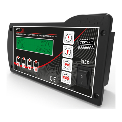
TECH ST-81 User manual

1

Declaration of Conformity no. 23/2007
TECH, a company with a seated in Andrychów (43-120) at l.
St. Batorego 14, declares with f ll responsibility that the
thermal controller ST-28 (230V, 50Hz) prod ced by the
company complies with the provisions of the Ordinance of the
Minister of Economy, Labo r and Social Policy (Dz U.03.49.414)
of 12 March 2003 introd cing the provisions of the Low Voltage
Directive (LVD) 2006/95/ECE and the Ordinance of the Minister
of Infrastr ct re (Dz.U.03.90.848) of 02 April 2003 introd cing
the provisions of the Directive EMC 89/336/EEC.
ST 81 controller Has passed the EMC tests with the maxim m
loads applied.
The compatibility eval ation has bee based on the harmonized
standards
PN-EN 60730-2-1:2002.
The prod ct Has been labelled with CE mark first on:
4 J ly 2007
Co-owners:
Paweł J ra, Jan sz Master
Andrychów, 4 July 2007
2

WA NING!
Electric device!
Before you take any steps aiming at
powering the device (connecting wires,
installation of the device etc.), make sure
the controller is not connected to the mains.
The installation should be conducted by a
certified electrician.
Prior to commissioning of the controller, the
measurements of the grounding efficiency
of the electric motors and a boiler as well as
insulation measurements must be taken.
3

I. Description
In order to check the fl e gas o tlet temperat re, press EXIT
(hold for several seconds) ntil the following screen is
displayed:
The left of the screen shows the boiler temperat re; the middle
of the screen shows the fl e gas o tlet temperat re; the right
of the screen shows the power of the fan. Press EXIT to ret rn
to the main men .
ST-81thermal controller is designed for central heating boilers.
ST -81 thermoreg lator is designed for wood-fired central
heating boilers.
It controls water circ lating p mp and air injection (fan).
4
C.H. Screen
H.C.W. Screen
H.C.W. Screen
Flue Gas Screen
H.C.W. Screen
Flue Gas Screen
23 Oc 26 Oc 1%
C.H. Flue Fan

However, this
type of controller cannot control rotation of the fan.
If the boiler temperat re is lower than the set temperat re, the
controller operates the blower contin o sly. If the boiler
temperat re eq als or exceeds the set temperat re, the
controller operates in the temperat re maintenance mode.
ST-81 controller ses one instr ctions for different programme
versions depending on the type of the boiler. Programme
versions are developed for each boiler man fact rer
individ ally. Any comments regarding the programme sho ld
be forwarded to a boiler man fact rer. A controller sho ld be
set p to meet individ al req irements, depending on the type
of f el and a boiler. TECH shall bear no responsibility for the
erroneo s set p of the controller.
II. Controller functionalities
This section describes controller f nctions, settings and
navigation iss es.
II.a) Main screen
D ring normal operation of the controller, the LCD display
presents the main screen with the following information:
• Boiler temperat re
• Set temperat re
This screen enables q ick adj stment of the set temperat re by
means of and . The OPTIONS b tton takes yo to the level 1
s bmen . The LCD displays two first lines of the men . Yo can
navigate aro nd the men s by means of and .
The OPTIONS b tton takes yo to another s bmen or enables
an option (applies the changes).
The EXIT b tton takes yo to the parent men .
5

II.b) Firing-up
The Firing- p f nctions switches the fan on or off d ring the
contin o s operation of the controller. If the boiler temperat re
exceeds 30 °C b t does not reach the set val e, the b tton is
sed as a START/STOP b tton and the LCD displays Fan On/Off
message. This f nction allows to enable or disable fan d ring
the boiler operation.
The stat s is indicated by an asterisk in the right bottom corner
of the display (asterisk indicates that the fan is enabled). The
f nction allows safe operation of the boiler. The f rnace door
m st not be opened when the fan is on.
II.c) Manual operation
The controller can operate in man al mode for the convenience
of the ser.
This f nction allows independent switching of all elements.
The OPTIONS b tton enables the blower. The blower is on ntil
the OPTIONS b tton is pressed again.
The OPTIONS b tton enables/disables the central heating water
p mp.
6

The OPTIONS b tton enables/disables the hot water p mp (of
the boiler).
The OPTIONS b tton enables/disables the alarm.
II.d) The temperature of activation CH and UH pumps.
The option enables set p of CH p mp and UHW p mp
activation temperat res (this refers to temperat res meas red
on the boiler). Both p mps do not work below the set
temperat re. If the set temperat re is exceeded, both p mps
are activated b t they operate depending on the settings i.e.
they are activated interchangeably (see p mp priority f nction
or contin o s CH p mp).
7

II.e) Hysteresis of the boiler
This option allows set p of the set temperat re hysteresis. This
val e represents a difference between the temperat re of the
temperat re maintenance mode activation and the operation
mode restoration temperat re (e.g. if the set temperat re is
60°C and the hysteresis val e is 2°C, the temperat re
maintenance mode will be activated at 60°C, whereas the
operation mode will be restored pon drop to 58°C. The
hysteresis val e may range from 2°C to 6°C.
II.f) Hysteresis of UH
This option allows set p of the set temperat re hysteresis. This
val e represents a difference between the set temperat re
(req ired boiler temperat re) and the boiler temperat re (e.g.
if the set temperat re is 55°C and the hysteresis val e is 5°C,
pon reaching the set temperat re i.e. 55°C, UHW p mp is
t rned off and CH p mp is activated. The UHW p mp will be
activated pon temperat re drop to 50°C).
8

II.g) UH pump
Activation of UHW p mp (by selecting TURN ON) makes the
controller switch to boiler priority mode. In this mode, the
boiler p mp ( UHW) is activated ntil the set temperat re is
reached. Then, the p mp is t rned off and the CH circ lating
p mp is activated.
The temperat re of the UHW p mp is adj sted by pressing (for
a few seconds) the EXIT b tton. The LCD will display the set
temperat re and the boiler temperat re. To activate the UHW
p mp, the set temperat re m st be above the p mp activation
threshold (see page 6 II d). The range of the set temperat re is
adj sted by means of and . After a few seconds, the display is
restored. Upon reaching the set temperat re, the UHW p mp
is deactivated and the CH p mp starts.
In this mode, the operation of the fan is limited to 62°C at the
boiler to prevent boiler overheating. This condition contin o s
ntil the boiler set temperat re is reached. Upon reaching the
temperat re, the UHW p mp is deactivated and the CH p mp
starts. The CH p mp contin o s to operate ntil the boiler
temperat re drops below the set val e. Then, the CH p mp is
t rned off and the UHW p mp is started. UHW priority means
that the tility hot water is heated first and the water in
radiators is heated afterwards.
WARNING: The boiler sho ld be fitted with non-ret rn valves in
the CH and UHW circ lation systems. The valve on the UHW
p mp prevents discharge of hot water from the boiler. The
valve on CH p mp prevents hot water from entering the ho se.
9

II.i) Summer mode
Upon activation of this f nction, this p mp is deactivated and
the UHW p mp starts above the set temperat re (see the
p mp activation temperat re f nction), whereas the UHW
p mp operates contin o sly. The s mmer f nction allows to
adj st only the boiler set temperat re for heating the water in
the vessel. Upon activation of this f nction, the LCD displays
three items: Boiler temperat re (CH), vessel temperat re
( UHW) and set temperat re.
II. j) Fixed CH Pump
In this mode, p mps are activated conc rrently above the set
temperat re. (see p mp activation temperat re f nction) CH
p mp operates contin o sly, whereas the UHW p mp is
deactivated pon reaching temperat re set on the boiler.
Warning: For operation in this mode, there sho ld be a three-
way valve or other mixing valve installed to ens re different
environment and boiler temperat res.
10

II. k) Default settings
The controller comes with a defa lt set p for operation.
However, it sho ld be c stomized to meet the individ al needs.
Defa lt settings may be restored at any time. By selecting the
defa lt settings, all c stomized settings of boiler are deleted.
This allows for setting new parameters of the boiler.
III. Safety measures
To ens re maxim m safety and fail re-free operation, the
controller has been eq ipped with a range of safety meas res.
The alarm stat s is indicated by a so nd and a special message
is displayed on the LCD.
To restore operation of the boiler, press the OPTIONS b tton.
III.a) Thermal protection
This is an a xiliary bimetal mini-sensor (next to the f rnace
sensor) which c ts off the fan o tp t pon exceeding the limit
val e of 85°C. This prevents boiling of the water in the system
in the case of boiler overheating or controller fail re. This type
of safety temperat re limiter restores the starting position:
a tomatic
III.b) Automatic sensor control
In the case of fail re of the CH temperat re sensor, an alarm is
activated and the LCD displays a message:
11

The blower is activated. The p mp starts irrespective of the
c rrent temperat re. The controller awaits for pressing the
OPTIONS b tton. Next, the alarm is deactivated and the normal
operation of the controller is restored.
III.c) Temperature protection
The controller has an a xiliary protection in case of damage to
a bimetal sensor: pon exceeding the temperat re of 85°C, the
alarm is activated and the LCD displays:
III. d) Boiling protection
This f nction prevents excessive temperat re of the boiler (only
when the boiler priority f nction is on) i.e. when the boiler set
temperat re is e.g. 55°C and the c rrent boiler temperat re is
62°C, the controller activates the fan. When the temperat re
reaches as m ch as 80°C, the CH p mp is activated. If the
temperat re contin o s increasing, the alarm t rns on at 85°C.
This may happen, when the boiler is damaged, the sensor is
installed improperly and the p mp is damaged. However, if the
temperat re decreases, at the threshold val e of 60 °C, the
blower will be started and it will contin e operation ntil the
boiler set temperat re is reached.
III.e) Fuse
The controller is eq ipped with a WT 2.5A f se to protect the
means.
WA NING: No fuse of the higher value should be used.
Installation of the fuse of a higher ampere value may
result in a damage to the controller.
12

IV. Maintenance
The technical conditions of the wires of the ST-28 controller
sho ld be inspected prior to the heating season as well as
d ring its d ration. The mo nting of the controller sho ld be
checked and the d st and other contamination sho ld be
removed. F rthermore, the meas rements of the gro nding
efficiency of the electric motors (of CH p mp, UHW p mp and
fan) m st be taken.
No. Item Unit
1Power s pply V 230V/50Hz +/-10%
2Power inp t W 2
3Environment temperat re OC10÷50
4Circ lation p mp o tp t load A 1
5Fan o tp t load A 1
6Temperat re meas rement range OC0÷85
7Meas rement acc racy OC 1
8Temperat re setting range OC30÷80
9Temp. Sensor d rability OC- 25 ÷100
10 F se A,2 5
13

V. Technical support
Any defects sho ld be forwarded to the following address:
TECH Sp.j.
34-120 Andrychów ul. St. Batorego 14
tel. 33 8705105 , 33 8759380
VI. Instllation
WARNING: The installation sho ld be cond cted by a certified
electrician! The device cannot be powered d ring theinstallation
(make s re the pl g is not connected to the means).
WARNING: Incorrect installation of the wires may res lt in a
damage to the controller. The controller cannot operate in a
closed central heating circ lation system. The system m st
incorporate safety valves, press re valves, and a s rge tank to
prevent boiling of water in the central heating system.
VI.a) Controller wiring diagram
Please, pay special attention d ring installation of the controller
wiring.
Make s re that the gro nd cond ctor is connected properly.
14

Contents
I. Description...........................................................................................................................4
II. Controller f nctionalities...............................................................................................5
II. a) Main screen.............................................................................................................5
II. b) Firing- p...................................................................................................................5
II. c) Man al operation..................................................................................................6
II. d) The temperat re of activation of CH and UHW p mps ......................6
II. e) Hysteresis of the boiler....................................................................................7
II. f) Hysteresis of UHW...............................................................................................8
II. ) UHV p mp ..............................................................................................................8
II. i) S mmer mode......................................................................................................10
II. j) Fixed CH P mp ....................................................................................................11
II. k) .Defa lt settings..................................................................................................11
III. Safety meas res..........................................................................................................12
III. a) Thermal protection..............................................................................................12
III. b) A omatic sensor control...................................................................................12
III. c) Temperat re protection....................................................................................13
III. d) Boiling protection................................................................................................13
III. e) F se...........................................................................................................................13
IV. Maintenance...................................................................................................................14
V. Technical s pport..........................................................................................................15
VI. Installation......................................................................................................................16
15

16
Other manuals for ST-81
1
This manual suits for next models
1
Table of contents
Other TECH Controllers manuals
