...............................................................................................................................................................................................................................................
Note: This guide does not replace the user manuals.Page 7-16
OR SETUP (CERVICAL SPINE)
BEFORE SCANNING
• Ensure the navigation system is connected.
• Avoid crossing a patient’s eyes with the positioning
laser.
Ensure that:
•Markerson
Airo
are visible to the camera.
• The patient is 5 cm minimum from the inner surface
of the ring bore to avoid skin burns.
• Staff have left the room or are shielded.
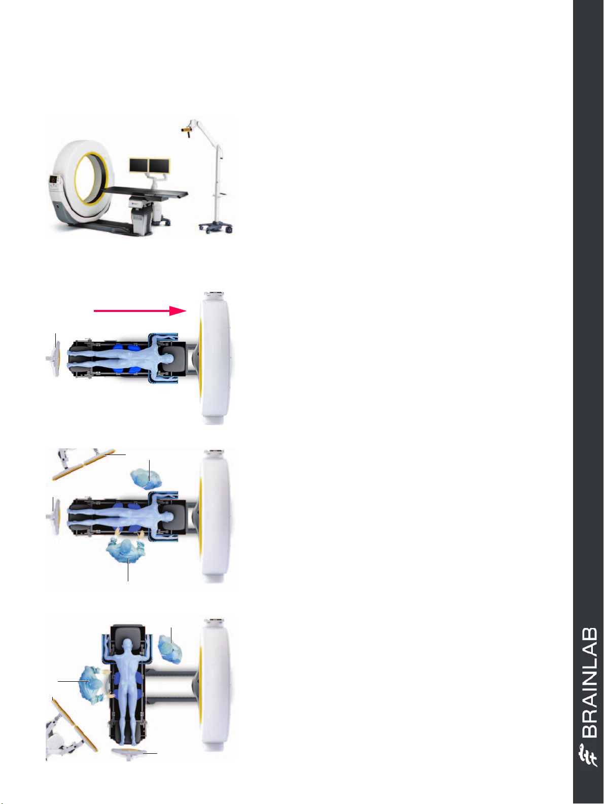
SCAN DIRECTION - SAB
SCANNING POSITION - HEAD FIRST
• Position the camera a at the table base.
• Position the patient on the table with the head facing
away from the camera.
• Remove the pendant and go to a safe area.
• Halt the patient’s respiration immediately prior to
scanning.
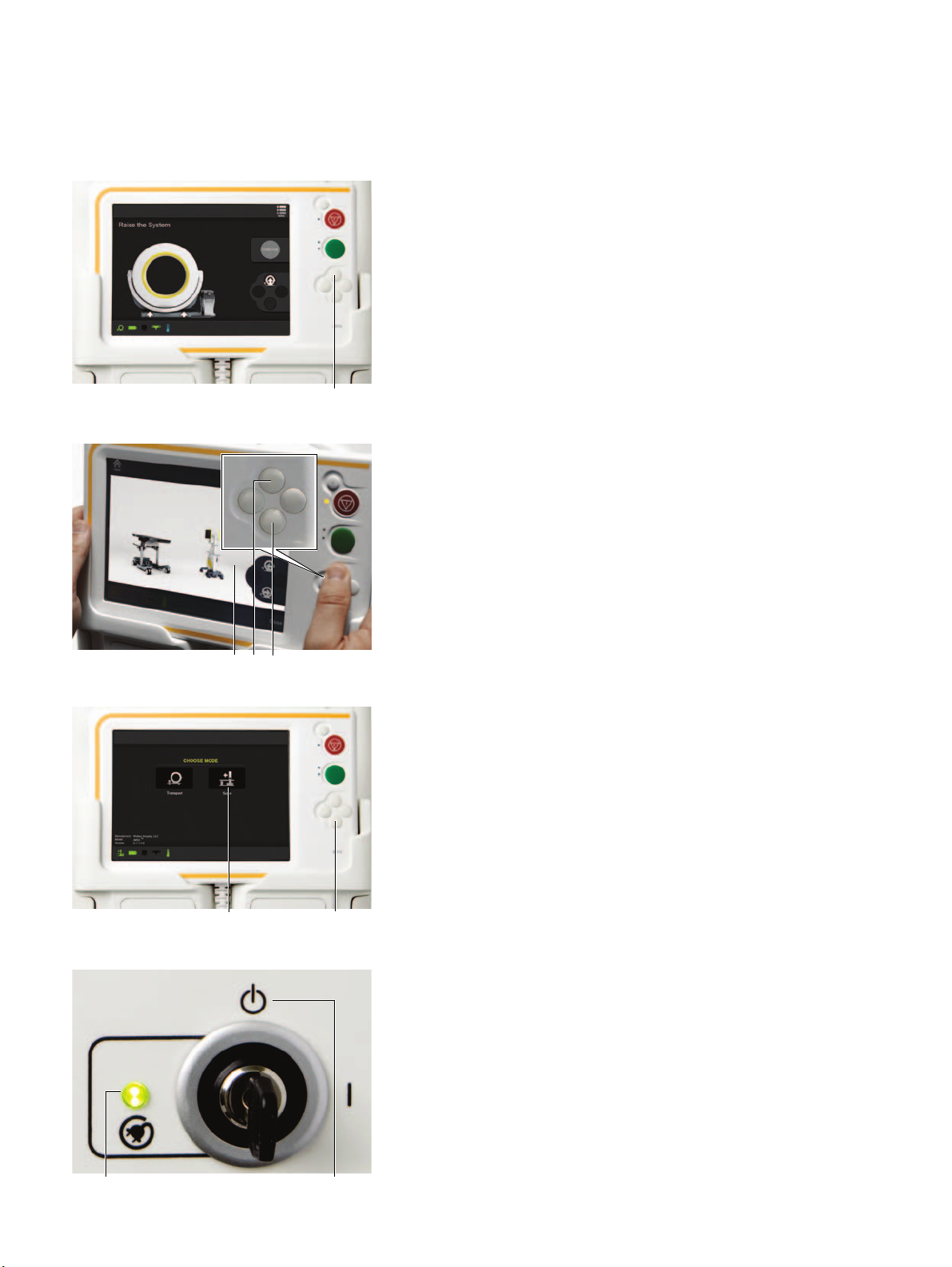
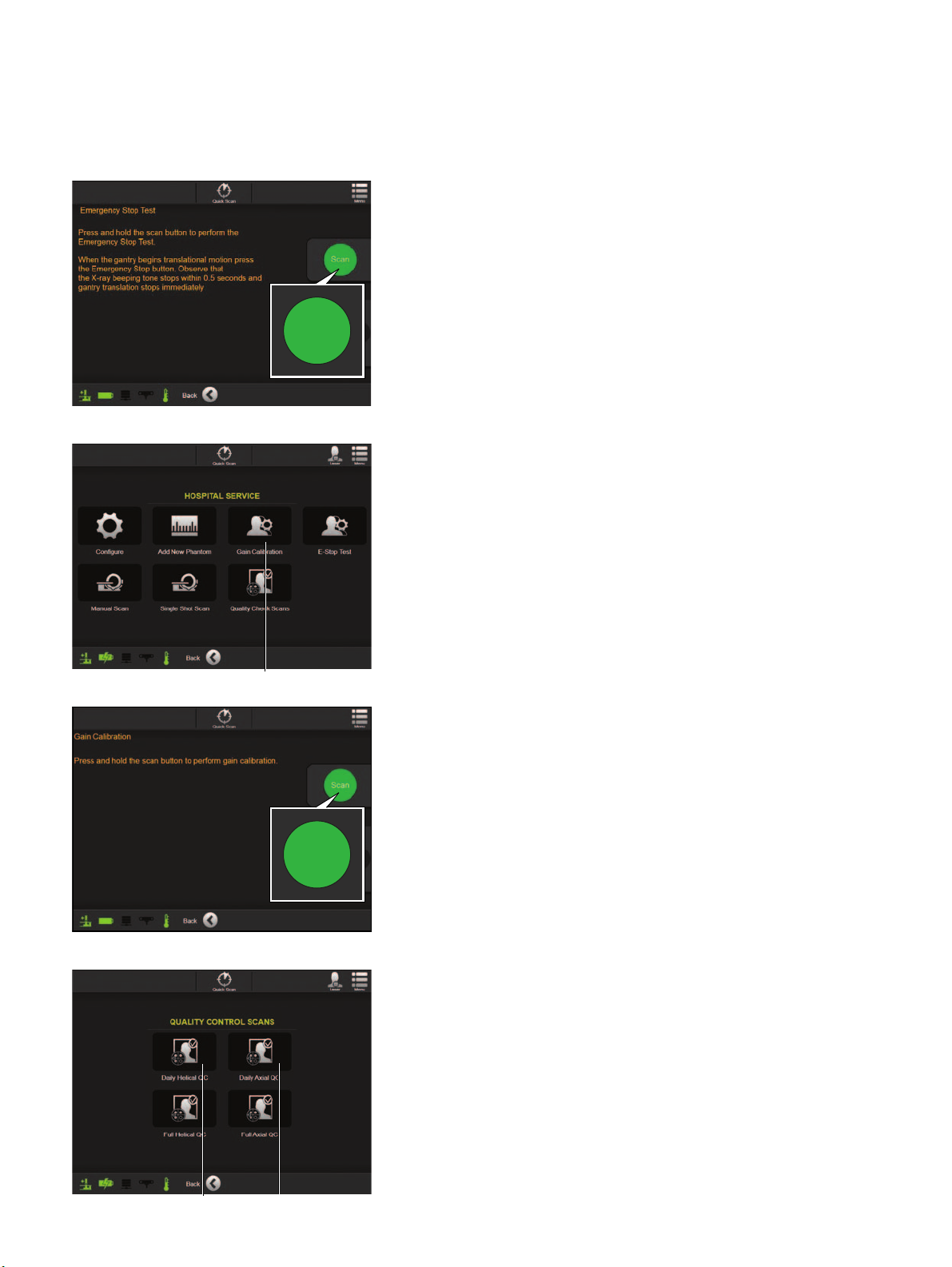
• Press and hold the
Scan
button during scanning and
follow prompts from the pendant.
OPERATING POSITION 1 - ROTATED 180 DEGS
•Movegantryg to the end of the rail and away from
the patient.
• Rotate the table 180 degrees.
• Ensure the equipment and medical staff are all
correctly positioned: Surgeon a, camera s,
anesthesiologist d and monitor f.
NOTE: Use 4 marker array for 180 degree rotations.
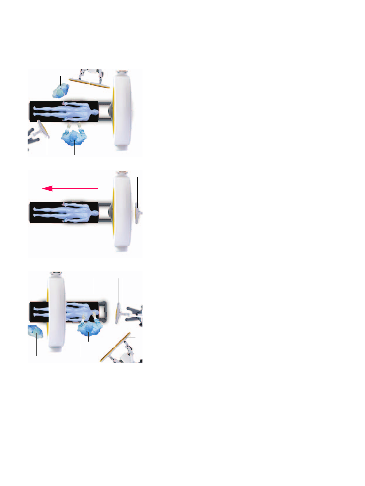
OPERATING POSITION 2 - ROTATED 90 DEGS
•Movegantryg to the end of the rail and away from
the patient.
• Rotate the table 90 degrees.
• Reposition the camera d.
• Ensure the equipment and medical staff are all
correctly positioned: Monitor a, surgeon s, camera
d and anesthesiologist f.
NOTE: Use 4 marker array for 90 degree rotations.
Hardware: Airo
Ensure the area is safe for X-ray exposure.