manuals.online logo
Brands
  1. Home
  2. •
  3. Brands
  4. •
  5. Mobotix
  6. •
  7. Security Camera
  8. •
  9. Mobotix c26 Instructions for use

Mobotix c26 Instructions for use

c26 Indoor 360°
Quick Install
32.851-003_EN_04/2018
c26 Standard Delivery
1.2
1.1
1.8
1.9
1.3
1.5
1.6
1.4
1.7
Item Count Part Name
1.1 1 Housing (installed)
1.2 1 Back plate with spring clips (installed)
1.3 1 Main board with lens MX-B016 or MX-B036 (installed)
1.4 2 Bayonet catch, blue (installed)
1.5 1 USB plug, blue (installed)
1.6 1 Ethernet plug, blue (installed)
1.7 1 Ethernet patch cable, 50 cm/19.7 in, black
1.8 1 MicroSD card pre-installed (SDHC installed, SDXC supported)
1.9 1 Disassembly tool
Connection and Initial Operation of the c26
Key
RecordingPower/Status
You can nd detailed information on the installation and connections of
the c26 in the Q25 Camera Manual (PDF, available on www.mobotix.com >
Support > Download Center > Documentation > Manuals).
Please note that the boot options of this camera have changed compared
to its predecessor (see «Boot Options of the c26») and the camera only has
one key. Regarding the rest of the initial operation of the c26, please see
the Q25 Camera Manual in Chapter 3, «Initial Operation».
Use a suitable device for operating the camera key (e.g., an opened paper
clip).
Installing the Mx-A-IOA-IC
For the Mx-c26A/B, you can use the optionally available Mx-A-IOA-IC to attach external sensors using the signal inputs
and to switch other devices via the signal outputs. When used with the the Mx-c26B, you can also attach MxBus devices
(e.g., an MX-GPS-Box).
1. Insert the Mx-A-IOA-IC
On the back of the camera, remove the sticker
that protects the receptacle and the camera’s
interior from collecting dirt (see red arrow in
gure to the right).
Carefully push the module board onto the
receptacle. Secure the module board using
the supplied Phillips screw (see red arrow in
gure).
When attaching the connection wires to the
Mx-A-IOA-IC, make sure the wires are guided to
the module without tension (you could apply
a cable tie and tie the wires to the network
cable, for example).
2. Attach the connection cables
Attach the connection wires as shown in the terminal connector overview.
Terminal Connectors
MxBus connectors MxBus functionality is only supported
by the camera variant Mx-c26B.
Output 1 A Relay
pot.-
free
–
Outputs
Output 1 B/GND Output 1
12 V
Output 1 12 V –
Output 2 A Relay
pot.-
free
–
Output 2 B/GND Output 2
12 V
Output 2 12 V –
Input 1 –
Inputs
Input 1 +
Input 2 –
Input 2 +
Inserting/Exchanging the SD Card
All camera models can use the integrated MicroSD card (SDXC) to record video data. In order to exchange the MicroSD card, please proceed as outlined
in the following instruction. For information on reliable SD cards, please see the MOBOTIX website www.mobotix.com > Support > Download Center >
Documentation > White Lists in the document MicroSD Card Whitelist for MOBOTIX Cameras. If the camera has not yet been installed, skip step 1.
Caution: In order to avoid damage from electrostatic discharge, you should touch a grounded device before opening the housing of the camera (e.g., the
blank metal at the back of a computer). This will remove any static electricity that may have built up.
1. Remove camera, remove cables
Pull the camera from its position by gently pulling
the camera downward on one side, then the other
side. Take care NOT to let the spring clips snap
forward (risk of injury!). Remove all cables that
are attached to the connectors on the back side.
2. Locate the locks
In order to remove the back plate, you will need
to push the delivered disassembly tool (item 1.9)
into the three holes on the back one aer the
other to release the locks (see red circles in gure).
3. Remove back plate
Insert the disassembly tool into a lock and press
rmly until you feel a perceptible resistance 1.
Gently push against the nearest spring clip to push
the lock out of its seat and to li the back plate
from the housing 2.
Repeat the process for the two other locks and
cautiously li the back plate from the housing.
4. Remove/insert SD card
If a MicroSD card has been installed, gently
press with your nger as indicated by the arrow
until you hear a click. Then release the SD
card. The card is protruding slightly and can
be easily removed.
Insert the new MicroSD card and gently press
with your nger as indicated by the arrow until
you hear the click.
5. Attach back plate
Make sure that the SD card is properly locked
in place, since the card can be damaged oth-
erwise. Begin by inserting the wide lock (next
to the SD card) into the camera housing as
shown. From the factory, the lock and the cor-
responding slot are highlighted by color mark.
Make sure that the two other locks are also
properly positioned, then press the back plate
into its seat until you hear all three locks click
into place.
6. Re-connect the cables
Insert the Ethernet cable and – if installed – the
USB cable into the corresponding sockets and
secure the connectors using the blue bayonet
catches.
Press the spring clips back and insert the
camera into its original mounting position
(see «Installing the c26»).
To nish, make sure that the camera image is properly aligned: If required,
cautiously turn the camera to adjust image alignment.
1
2
Click!
Installing the c26
Use the drilling template on the back for this purpose (red circle) or draw a circle with 105 mm/4.13 in diameter for the cut-out. Cut
out the hole for the camera, then guide the Ethernet cable and any other cables you want to attach to the camera through the hole.
1. Connect the cables
Insert the cables into the appropriate connec-
tors and fasten them using the blue bayonet
catches.
Make sure that the camera points into the
desired direction: The icon on the back (black
arrow) shows the "up" direction of the image.
2. Install the c26
Press the spring clips back and insert the c26
into the hole for the camera. The spring clips
will snap outwards, thus rmly holding the
camera in place.
Make sure that you only press back the spring
clips as shown in the image. Do not press them
back any further as the springs may snap out
of their xtures otherwise.
Ethernet
USB
"Up"
Removing the c26
1. Pull out the camera
Pull the camera from its position by gently pull-
ing the camera downward on one side, then
the other side. Take care NOT to let the spring
clips snap forward (risk of injury!).
2. Remove the cables
Remove the cables coming from the building (network cable, USB cable,
MxBus and signal input/output wires). Pull out the camera.
Initial Operation of the c26
The initial operation starts with connecting the power supply (see section «Network and Power Connection, Additional Cables»
in the Q25 Camera Manual). The rst access follows the procedure described in the same manual in the section «Initial Operation
of the Camera». All other tasks require access to the camera’s user interface in the browser. Enter the camera’s IP address into the
address bar of the browser (user "admin", password "meinsm"; password must be changed upon rst login – camera soware
V5.1.x and higher).
1. Conguring and Using the Mx-A-IOA-IC
The camera will automatically detect an installed
Mx-A-IOA-IC (see Camera Status, System section
in browser).
The signal inputs can be used right away in the
signal input proles in the Setup Menu > Event
Overview. Likewise, the signal outputs can be used
in the signal output proles in Admin Menu >
Hardware Conguration > Signal Out Proles.
In addition, the signal inputs/outputs have been entered automatically in
the Admin Menu > Assign Wires dialog and can be used to control doors
and lights.
To use one or both signal outputs not as potential-free outputs (for relays),
but as 12 V outputs, open the Admin Menu > Hardware Conguration >
Manage Hardware Expansions dialog. In the MxBus/IO Board section,
click on Connect for each output you want to use.
2. Save the conguration
In the live image of the browser, select the Manage Settings quick control
and set Store Entire Conguration as value. The camera stores the con-
guration in the permanent camera memory so that the settings will be
applied at the next camera reboot.
Output 1
Output 2
Variants/Accessories
Mx-c26A/B*
with lens B016
Mx-c26A/B*
with lens B036
Mx-A-IOA-IC
for MxBus modules* and
signal inputs/outputs
*Variant Mx-c26B supports MOBOTIX MxBus modules
Further information on www.mobotix.com:
• Products > Indoor Cameras > c26 Indoor 360°
• Support > Download Center > Documentation > Certicates & Declarations of Conformity
MOBOTIX, the MX logo, MxPEG and MxActivitySensor are trademarks of MOBOTIX AG registered in the Euro-
pean Union, the U.S.A., and other countries • Information subject to change without notice • MOBOTIX does
not assume any liability for technical or editorial errors or omissions contained herein • All rights reserved •
© MOBOTIX AG 2017
Important Notes
Safety Warnings
Notes on Installing:
• This product must not be used in locations exposed to
the dangers of explosion.
•
Make sure that you install this product as outlined in the instructions
of this Quick Install document. A faulty installation can damage the
camera!
• When installing this product, make sure that you are only using gen-
uine MOBOTIX parts and MOBOTIX connection cables.
• Only install this product on suitable, solid materials that provide for
a sturdy installation of the xing elements used.
Electrical installation: Electrical systems and equipment may
only be installed, modied and maintained by a qualied
electrician or under the direction and supervision of a quali-
ed electrician in accordance with the applicable electrical guidelines.
Make sure to properly set up all electrical connections.
Electrical surges: MOBOTIX cameras are protected against
the eects of small electrical surges by numerous measures.
These measures, however, cannot prevent the camera from
being damaged when stronger electrical surges occur. Special care should
be taken when installing the camera outside of buildings to ensure proper
protection against lightning, since this also protects the building and the
whole network infrastructure.
Max. power consumption of attached extension modules:
The power consumption of all attached MxBus modules must
not exceed 2,5 W. When attaching modules to the MxBus
connector and the USB socket, the power consumption of all attached
modules must not exceed 3 W, if the camera is powered by PoE class 3.
If PoE class 2 is used, the power consumption of all attached modules
must not exceed 1 W!
Never touch the lens: Due to the high performance of the c26,
the area of the image sensor can get quite hot, especially when
the ambient temperature is also high. This does not aect the
proper functioning of the camera in any way. For this reason, the product
must not be installed within the reach of persons.
Power o before opening the camera: Make sure the power
supply to the camera is disconnected before opening the
camera housing (e.g., when exchanging the SD card or when
opening the body to attach wires).
Network security: MOBOTIX products include all of the nec-
essary conguration options for operation in Ethernet net-
works in compliance with data protection laws. The operator
is responsible for the data protection concept across the entire system.
The basic settings required to prevent misuse can be congured in the
soware and are password-protected. This prevents unauthorized parties
from accessing these settings.
Legal Notes
Legal aspects of video and sound recording: You must com-
ply with all data protection regulations for video and sound
monitoring when using MOBOTIX products. Depending on
national laws and the installation location of the c26, the recording of
video and sound data may be subject to special documentation or it may
be prohibited. All users of MOBOTIX products are therefore required to
familiarize themselves with all applicable regulations and to comply with
these laws. MOBOTIX AG is not liable for any illegal use of its products.
Disposal
Electrical and electronic products contain many valuable
materials. For this reason, we recommend that you dispose of
MOBOTIX products at the end of their service life in accordance
with all legal requirements and regulations (or deposit these
products at a municipal collection center). MOBOTIX products must not be
disposed of in household waste! If the product contains a battery, please
dispose of the battery separately (the corresponding product manuals
contain specic directions if the product contains a battery).
Disclaimer
MOBOTIX AG does not assume any responsibility for damages,
which are the result of improper use or failure to comply to the
manuals or the applicable rules and regulations. Our General
Terms and Conditions apply. You can download the current version of the
General Terms and Conditions from our website at www.mobotix.com
by clicking on the COS link at the bottom of every page.
§
§
Boot Options of the c26
By default, the camera starts as DHCP client and automatically tries to get
an IP address from a DHCP server. To start the camera in a mode dierent
from the default mode, you can activate the boot menu of the camera.
1. Prepare the Camera
• Disconnect the camera's power supply.
• Make sure that you have suitable item such as a paper clip at hand,
but never use sharp or pointed objects!
• Reconnect the power supply of the camera.
2. Activate the Boot Menu
The red LED lights up 5 to 10 seconds aer establish-
ing the power supply and will stay on for 10 seconds.
Briey press the key by inserting the paper clip into
the hole indicated by the red circle in the gure. The
camera enters the boot menu, ready for selecting one
of the boot options.
The LED now ashes once and repeats the ash signal
aer pausing for one second (the number of ashes
indicates the current boot option). To go to the next
boot option, briey press the key again (< 1 sec). Aer
the last boot option, the camera returns to the rst
option (LED ashes once).
LED
ashes
Boot
Option Meaning
Audio
Conrma-
tion*
1 x —This option is not used on this camera
model. —
2 x Factory
Defaults
Starts the camera with factory defaults
(factory default IP address, users and
passwords will not be reset).
Boing
3 x Automatic
IP Address
Starts the camera as DHCP client and
tries to obtain an IP address from a DHCP
server. If a DHCP server cannot be found
or no IP address can be obtained, the
camera starts with its factory default
address.
Boing Boing
4 x Recovery
System
Starts the camera with the recovery sys-
tem, e.g., in order to recover from a failed
update of the camera soware.
Alarm Sound
*Only on cameras with audio option and installed speaker.
3. Select a Boot Option
Press the paper clip longer (> 2 sec) into the hole. The camera conrms the
selection by ashing rapidly three times. You can now remove the paper
clip. Aer 20 sec, the camera will conrm the selection by playing a sound
according to the table above.
If nothing is selected, the camera will resume its normal boot process
aer a certain time.
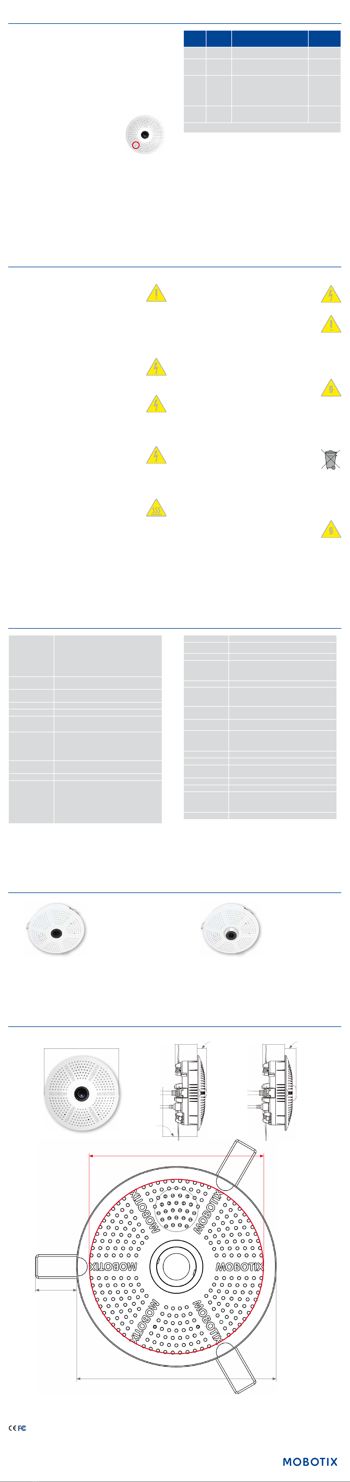
Dimensions/Drilling Template
Outside diameter 120 mm/4.72 in
Cut-out diameter 105 mm/4.13 in
25 mm/0.98 in
c26 with lens B036
36 mm/1.42 in 20 mm/
0.79 in
c26 with lens B016
36 mm/1.42 in 15 mm/
0.59 in
Recommended
min. instal-
lation depth
55 mm/2.17 in
Forms of c26
Mx-c26A/B with lens B016 Mx-c26A/B with lens B036
Technical Specications c26
Model Variants
Mx-c26A/B*-6D016/036 (daylight image sensor, color)
Mx-c26A/B*-6N016/036 (night image sensor, Black&White)
Mx-c26A/B*-AU-6D016/036 (audio package, daylight image sensor,
color)
Mx-c26A/B*-AU-6N016/036 (audio package, night image sensor,
Black&White)
*Variant Mx-c26B supports MOBOTIX MxBus modules
Lens Options B016 (180° horizontal image angle)
B036 (103° horizontal image angle)
Sensitivity Color sensor (daylight): 0.1 lx @ 1/60s; 0.005 lx @ 1s
Black&White sensor (night): 0.02 lx @ 1/60s; 0.001 lx @ 1s
Image Sensor 1/1.8“ CMOS, 6MP (3072x2048), Progressive Scan
Max. Image Size 6MP (3072x2048)
Image Formats
Freely congurable 4:3, 8:3, 16:9 or custom formats (image
cropping), e.g., 2592x1944 (5MP), 2048x1536 (QXGA), 1920x1080
(Full-HD), 1280x960 (MEGA)
Max. Frame Rate
MxPEG: 42@HD(1280x720), 34@Full-HD, 24@QXGA, 15@5Mp,
12@6MP
M-JPEG: 26@HD(1280x720), 13@Full-HD, 9@QXGA, 5@5Mp,
4@6MP
H.264: 25@Full-HD, 20@QXGA
Video Codec MxPEG, M-JPEG, JPEG (max. output size 6MP)
H.264 (max. output size QXGA, bandwidth limitation applicable)
ONVIF ONVIF-S (camera soware V5.0.2.x and higher)
DVR
In the camera on MicroSD card (SDXC, SDHC pre-installed)
External, on USB device
External, on NAS
Separate live image and full image recording – MxFFS with
archiving function
Pre- and post-alarm images
Automatic DVR monitoring with error notication
Soware MxManagementCenter
Image Processing MxLEO, backlight compensation, automatic white balance,
distortion correction
PTZ Digital pan/tilt/zoom, continuous up to 8X
Alarm/Events
Temperature sensor, shock detector (with rmware version 5.0.1
and higher), microphone (Mx-c26A/B-AU only), additional sensors/
IOs via MxMessageSystem, notication via e-mail, FTP, IP tele-
phony (VoIP, SIP)
Intelligent Video Analysis MxActivitySensor, video motion analysis, MxAnalytics
Audio
(only Mx-c26A/B-AU with
audio package)
Microphone/speaker, both 16bit/16kHz (HD wideband audio)
Lip-synchronous audio, audio recording
VoIP/SIP telephony, intercom, remote controlling using key codes
Interfaces Ethernet 100BaseT (MxRJ45), MiniUSB (MxMiniUSB), MxBus*
*Only variant Mx-c26B
Security User/group management, HTTPS/SSL, IP address lter, IEEE
802.1x, intrusion detection, digital image signature, MxFFS
Certications
EN55022:2010; EN55024:2010; EN50121-4:2015, EN61000-6-1:2007;
EN 61000-6-2:2005, EN61000-6-3:2007+A1:2011, EN61000-6-
4:2007+A1:2011, AS/ NZS CISPR22:2009+A1:2010, CFR47 FCC
Part15B
Power Supply Power over Ethernet IEEE 802.3af
Power Consumption Typ. 4 W
Power Consumption of
External Devices
At MxBus: max. 2,5 W, at USB: max. 2.5 W, total max. 3 W
The power consumption of the camera will increase accordingly!
Protection Classes IP20, IK06
Ambient Temperature 0 to 40°C/32 to 104°F
Dimensions
Outside diameter 120 mm/4.72 in, total height 51 mm/2.01 in with
B016, 56 mm/2.21 in with B036, height installed 15 mm/0.59 in
with B016, 20 mm/0.79 in with B036, cut-out diameter
105 mm/4.13 in, rec. min. installation depth 55 mm/2.17 in
Weight Approx. 212 g

Other manuals for c26

1

This manual suits for next models

2

Other Mobotix Security Camera manuals

Mobotix MX-c25 Instructions for use

Mobotix

Mobotix MX-c25 Instructions for use

Mobotix v26 Instructions for use

Mobotix

Mobotix v26 Instructions for use

Mobotix D16 DualDome Instructions for use

Mobotix

Mobotix D16 DualDome Instructions for use

Mobotix M24M Allround CS-Vario Assembly instructions

Mobotix

Mobotix M24M Allround CS-Vario Assembly instructions

Mobotix D12 User manual

Mobotix

Mobotix D12 User manual

Mobotix D26 Dome Instructions for use

Mobotix

Mobotix D26 Dome Instructions for use

Mobotix D12 User manual

Mobotix

Mobotix D12 User manual

Mobotix Q22M User manual

Mobotix

Mobotix Q22M User manual

Mobotix D16 DualDome Instructions for use

Mobotix

Mobotix D16 DualDome Instructions for use

Mobotix M22M User manual

Mobotix

Mobotix M22M User manual

Mobotix Mx-D26A Original operating instructions

Mobotix

Mobotix Mx-D26A Original operating instructions

Mobotix D14 User manual

Mobotix

Mobotix D14 User manual

Mobotix Q25 Instructions for use

Mobotix

Mobotix Q25 Instructions for use

Mobotix Allround M26 Instructions for use

Mobotix

Mobotix Allround M26 Instructions for use

Mobotix CamIO User manual

Mobotix

Mobotix CamIO User manual

Mobotix V16 Instructions for use

Mobotix

Mobotix V16 Instructions for use

Mobotix Mx-SD1A-230-LL Original operating instructions

Mobotix

Mobotix Mx-SD1A-230-LL Original operating instructions

Mobotix D16 DualDome Instructions for use

Mobotix

Mobotix D16 DualDome Instructions for use

Mobotix v26 Instructions for use

Mobotix

Mobotix v26 Instructions for use

Mobotix S15 User manual

Mobotix

Mobotix S15 User manual

Mobotix D15D User manual

Mobotix

Mobotix D15D User manual

Mobotix MOBOTIX M73 User manual

Mobotix

Mobotix MOBOTIX M73 User manual

Mobotix D16 DualDome User manual

Mobotix

Mobotix D16 DualDome User manual

Mobotix MOBOTIX M73 Original operating instructions

Mobotix

Mobotix MOBOTIX M73 Original operating instructions

Popular Security Camera manuals by other brands

LEGRAND VADDIO EasyIP 30 installation guide

LEGRAND

LEGRAND VADDIO EasyIP 30 installation guide

TeleEye NF610 III Plus NF Series installation guide

TeleEye

TeleEye NF610 III Plus NF Series installation guide

Lorex VANTAGE LND2152 SERIES quick start guide

Lorex

Lorex VANTAGE LND2152 SERIES quick start guide

Panasonic WV-SFV531 installation guide

Panasonic

Panasonic WV-SFV531 installation guide

Lorex LEV2522 quick start guide

Lorex

Lorex LEV2522 quick start guide

Vivotek CD8371-HNVF2 Quick installation guide

Vivotek

Vivotek CD8371-HNVF2 Quick installation guide

SECO-LARM Enforcer Video EV-1354C12(PAL) Specification sheet

SECO-LARM

SECO-LARM Enforcer Video EV-1354C12(PAL) Specification sheet

Panasonic WV-CP310 installation guide

Panasonic

Panasonic WV-CP310 installation guide

OMNI-IP KNC-p3DR28V12IR Quick operation guide

OMNI-IP

OMNI-IP KNC-p3DR28V12IR Quick operation guide

Wisenet SND-L6013 quick guide

Wisenet

Wisenet SND-L6013 quick guide

Blaupunkt VIO-HS20 quick start guide

Blaupunkt

Blaupunkt VIO-HS20 quick start guide

OpenEye CM-511 user manual

OpenEye

OpenEye CM-511 user manual

SECO-LARM ENFORCER EV-122C-VWA3 manual&nbsp;

SECO-LARM

SECO-LARM ENFORCER EV-122C-VWA3 manual&nbsp;

Challenger SLDCRF user manual

Challenger

Challenger SLDCRF user manual

urmet domus DS1092-536 quick guide

urmet domus

urmet domus DS1092-536 quick guide

Zavio CB5220 user manual

Zavio

Zavio CB5220 user manual

Spectur HD5 Assembly/installation instructions

Spectur

Spectur HD5 Assembly/installation instructions

DSE SD-E10FD owner's manual

DSE

DSE SD-E10FD owner's manual

manuals.online logo
manuals.online logoBrands
  • About & Mission
  • Contact us
  • Privacy Policy
  • Terms and Conditions

Copyright 2025 Manuals.Online. All Rights Reserved.