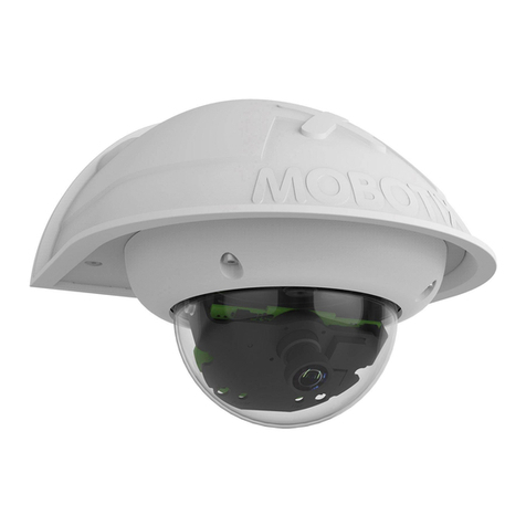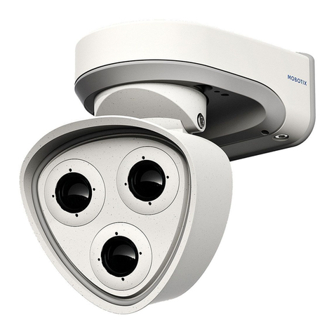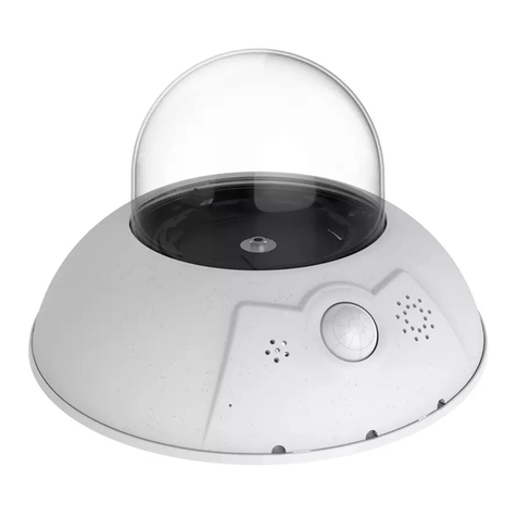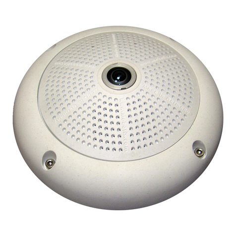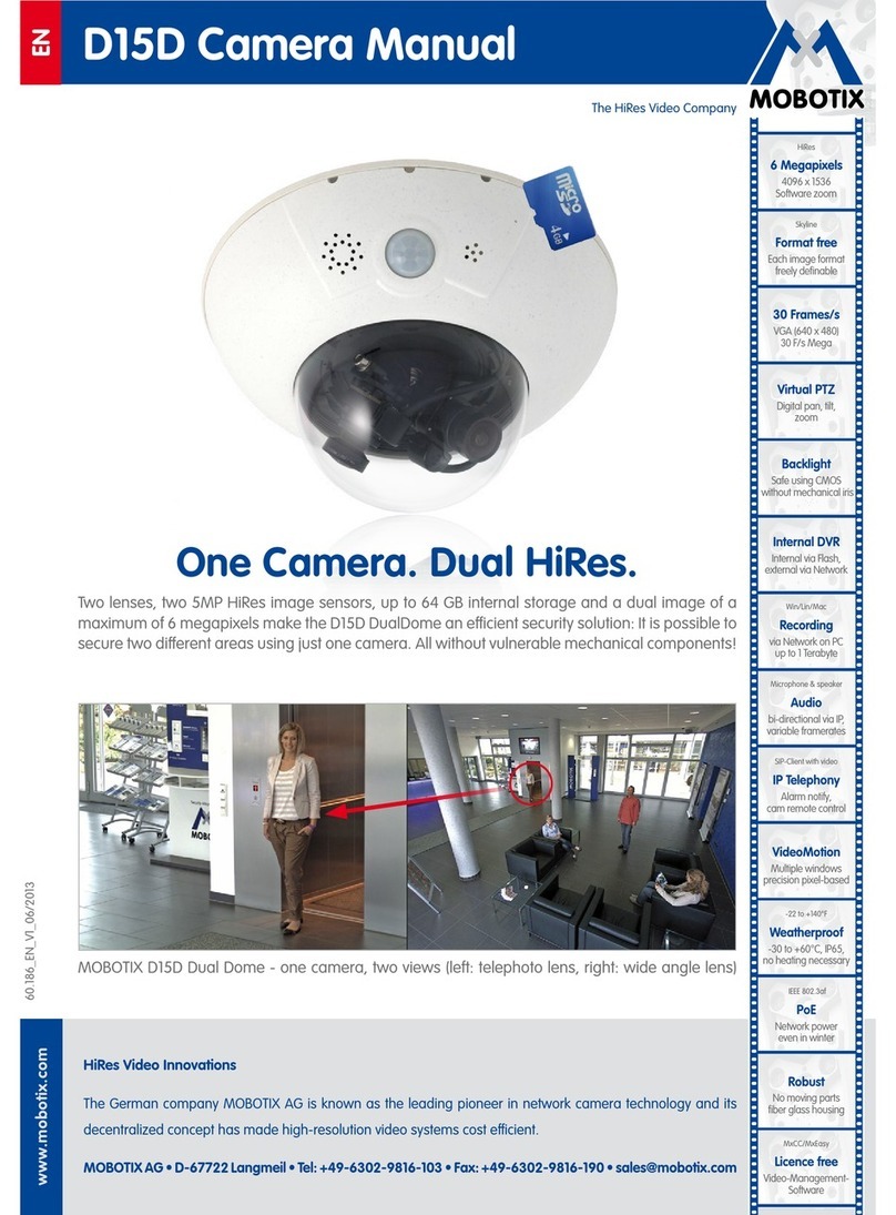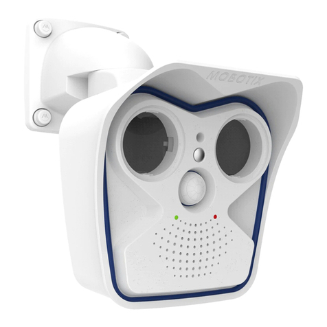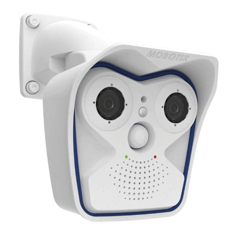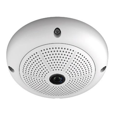
MX-TubeMount
32.567-003_EN_02/2017
Quick Install
MxTubeMount
Cameras with
MxTubeMount
Preparing the Installation
1. Prepare the Tube
If you are using the mount without sup-
plied tube, cut the tube to size (max.
length aluminum tube 2 m/6.6 , steel
tube 1.6 m/5.2 ). If the external diameter
of the tube is less than 30 mm/1.18 in,
make sure to use the supplied adjust-
ment bushings. The external diameter
with adjustment bushing should be between 29.7 and 30.4 mm/1.169
and 1.197 in.
2. Install Suitable Carriers at the Beams (optional)
Take care not to damage or weaken any
structurally relevant parts of the ceiling.
Use suitable support frames to install the
mount at i-beams, for example.
3. Break Out Cable Guide at the Side (optional)
If you are running the cables from the side
and not from the rear, you should break
out one or more of the four cable guides.
4. Drill Holes (if required)
Drill the holes for the mounting screws for
the top mount using the supplied drilling
template on the back.
Installing the MxTubeMount
1. Attach the Safety Wire at the Top Mount
Shorten the safety wire (item 1.12) so that
the nished wire is not longer than the
overall length of the entire length of the
unit plus 20 cm/7.87 in. Apply the crimp
tting of the safety wire, create a loop
the same size as the prefabricated loop
and crimp the tting using a suitable tool.
Caution:
To securely fasten the wire,
make that the
diameter of the loop is
no larger than 6 mm/0.24 in
.
Using one of the Filister head screws 4x14
(item 1.11), attach the safety wire at the
proposed location in the top mount (red
circle in the g., torque 2 Nm).
As an alternative, you can also attach the safety wire to the ceiling. For
this purpose, you can use one of the supplied wood screws (item 1.9) with
a dowel (item 1.10) and a washer (item 1.8). If you are using a dierent
type of screw, make sure that the wire loop is completely covered by
the screw head or that you use an additional washer.
2. Connect the Cables
Lead the cables from the top or from the
side to the mount. If the cables are coming
from the side, cut or break out one of
the cable guides (red circles in gure).
Guide the cable and the safety wire
through the top mount. To prevent
pinching the cables when entering from
the side, make sure that you guide the
cables through the gaps in the mount
(blue arrows in gure).
3. Install the Top Mount
Install the top mount at its position
using the wood screws (item 1.9), dow-
els (item 1.10) and washers (item 1.8) or
by other suitable means.
4. Insert the Tube into the Top Mount
Guide the cable and the safety wire
through the tube. Insert the tube (with
adjustment bushing, if required, see
«Preparing the Installation»
) into the top
mount and fasten the set screws of the mount in alternating fashion
(torque 1.5 Nm).
5. Install the Bottom Mount
Guide the cable and the safety wire
through the bottom mount.
Push the bottom mount onto the tube
(with adjustment bushing, if required, see
«Preparing the Installation»
) and fasten the
set screws of the mount (torque 1.5 Nm).
6. Attach the Safety Wire at the Bottom Mount
Using one of the Filister head screws 4x14
(item 1.11), attach the safety wire at the
proposed location in the bottom mount
(red circle in the g., torque 2 Nm).
Make sure that the safety wire is now fastened at the ceiling or the top
mount and the bottom mount.
7. Apply Cover Disc (M15, M25, PTMount, PTMount-Thermal
only)
Lead the cables through the cover disc
and aix them at the bottom mount as
follows:
•
M15/M25:
Break out the pre-cut holes
and insert the cover disc between the
mount and the ceiling mount using
the cylinder head screws M6x25 mm
(item 1.7), two washers each (item 1.8)
and hex nuts (item 1.6).
•
PTMount/PTMount-Thermal:
Insert
the cover disc between the mount
and the PTMount base plate and the
adapter ring using four Filister head
screws 4x14 (item 1.11).
Standard Delivery
1.1
1.2
1.3
1.4
1.14
1.13
1.5
1.6
1.7
1.10
1.9
1.8
1.11
1.12
Item Count Part Name
1.1 2 MxTubeMount support with 2 set screws each (installed)
1.2 1 Aluminum tube 1 or 2 m (3.3/6.6 , optional)
1.3 2 Adjustment bushing 1
1.4 2 Adjustment bushing 2
1.5 1 Cover disc
1.6 4 Hex nut M6
1.7 4 Cylinder head screw M6x25 mm, stainless steel
1.8 13 Washer 6.4 mm dia., stainless steel
1.9 5 Wood screw 6x50 mm, stainless steel
1.10 5 Dowel S8
1.11 6 Filister head screw KA4x14 mm, stainless steel
1.12 1 Safety wire 2.2 m/7.2 with 1 loop and 1 crimp tting
1.13 1 Allen wrench 5 mm
1.14 1 Allen wrench 2.5 mm
Install D25/Q25/PTMount/PTMount-Thermal at the MxTubeMount
Attach the OnWall Set D25/Q25/OnWall Set D25/Q25 10° or the PTMount/PTMount-Thermal to the bottom mount of the MxTubeMount (using the cover
disc for the latter two) as shown below using the Filister head screws 4x14 mm (item 1.11). When using the OnWall Set D25/Q25/OnWall Set D25/Q25 10°,
you can drill a hole into the base plate to conceal the cabling on its way into the on-wall set.
D25 Q25
with OnWall Set D25/Q25 or OnWall Set D25/Q25 10°
recommendation: drill hole in the center of the on-wall set to
provide for concealed cabling
+
PTMount-ThermalPTMount
with cover disc
1.11
1.11
Suspended Installation of MOBOTIX
c25, D25, M15, M25, p25, Q25, v25 and
PTMount/PTMount-Thermal
Set for suspended installation of MOBOTIX cameras and sensor modules
from ceilings and beams, mounting supplies included.
More Information:
www.mobotix.com > Products > Home Automation > MxTubeMount
• Can be ordered with tubes 1 or 2 m (3.3/6.6 ); also suited for stan-
dard aluminum tubes with 30 mm/1.18 in diameter and steel tubes
3/4".
• MxTubeMount for MOBOTIX cameras/sensor modules (not included):
• c25/p25 with On-Wall Mounting Set
• D25/Q25 with OnWall Set D25/Q25 or OnWall Set D25/Q25 10° (acces-
sory)
• M15/M25 with Ceiling mount (included in camera delivery)
• PTMount/PTMount-Thermal
• For concealed cabling from the rear or on-wall cabling from the side.
