Mod K-700 User manual

Use these instructions and your vintage Fender guitar amplifier to learn:
How to convert the “Bass Instrument” channel of a Bassman amp into a tremolo
effect for the “Normal Channel”.
BASS TO TREMOLO CONVERSION KIT (K-700)
1Copyright © 2011 by modkitsdiy.com
100k
INTENSITY
50k-
RA
220k
.01µ
.modkitsdiy.com

Table of Contents
Safety ……………………………………………………3
arts List ……………………………………………4, 5
Tools …………………………………………................6
Soldering Tips ……………………………………7, 8
reliminaries ……………………………………………9
Test oints …………………………………………...10
Bass to Tremolo Modification …………………...11 – 24
2
Style A …………………………………………...12 – 17
Style B ……………………………………………18 – 23
Schematics …………………………………………...12, 18
Terminal Strip Mounting Tips …………………...24

DANGER HIGH VOLTAGE MAY BE PRESENT
BE CAREFUL!
Safety
“Caution: to prevent electrical shock,
do not remove chassis or metal cover attached to chassis.
No user serviceable parts inside.
Refer servicing to qualified personnel only.”
-the back of an amp
We have quoted the back of an amp to stress the importance of putting safety first when
working on this type of equipment. Tube amps operate at high voltages which have the
potential to kill. Only work on an amp when you are wide awake and sober.
lease make sure you do the following before opening your amp:
Turn the power switch off.
Turn the standby switch off (down position).
Unplug the power cord.
Give the power tubes 10 minutes to cool down.
When the amp is open:
Use a volt meter with alligator clips to measure for high voltage at several test points.
(see the “ reliminaries” section for details)
Use the one-hand rule.
(see the “ reliminaries” section for details)
ON STANDBY
UNPLUG
OFF
3

4
.1µF
30V
bro n
black
yello
gold
100K
Parts List
art Number Quantity Description
C-MD1-630 1 0.1µF capacitor
C-MD01-630 2 0.01µF capacitor
C-MD022-630 1 0.022µF capacitor
.022µF
30V
.01µF
30V
R-A100K 3 100kΩ, ½W resistor
R-A1M 2 1MΩ, ½W resistor
bro n
black
green
gold
1M
R-A3M 1 3MΩ, ½W resistor
orange
black
green
gold
3M
R-A8D2M 1 8.2MΩ, ½W resistor
grey
red
green
gold
8.2M
R-A220K 1 220kΩ, ½W resistor
red
red
yello
gold
220K
R-A2D7K 1 2.7kΩ, ½W resistor
red
violet
red
gold
2.7K
C-ET22-50 2 22µF polarized capacitor
22µF 5 V

Parts List (continued)
art Number Quantity Description
R-VO 1020 1 Optocoupler
3
M
EG
5
0K
R-VC50K-RA 1 50kΩ potentiometer (reverse audio taper)
R-VC3M-RA 1 3MΩ potentiometer (reverse audio taper)
W-SC-11 1 ¼“ input jack
-H35-242 1 D DT slide switch
5
S-W809L 15 ft 20 AWG solid core hook-up wire (white)
-0501H 3 5 lug terminal strip (3rd lug common)
R-B1D5K 1 1.5kΩ, 1W resistor
bro n
green
red
gold
1.5K
(This value is used in amps with shared preamp tube
cathodes only – Like Bassman 100)

Tools
1. Digital Multi-Meter (DMM) – a meter for measuring voltage, current, resistance, and
sometimes capacitance.
2. Alligator Clip Test Leads – connect to your DMM for hands free measurements. These
are useful when setting the power tube bias and for safety when taking electrical
measurements.
3. Soldering Station – soldering iron with a 1/8” screwdriver tip and a variable control
capable of producing 25-40Watts. This will allow you to do some precise soldering of circuit
components and wires (do not use a soldering gun for soldering of electronic circuits).
4. Solder – 60/40 rosin core solder.
5. De-soldering Pump or Bulb – this will assist you in removing solder for circuit
modifications and correcting connection errors.
6. Wire Strippers
7. Cutting Pliers – These are great for cutting leads on resistors, capacitors, etc. before and
after soldering.
8. Needle Nose Pliers – 6” long are good for bending component leads and holding
components leads while de-soldering.
9. Screwdrivers – hillips

Soldering Tips (circuit boards)
Work in a ventilated area with a fan to blow the smoke from your face.
Allow the soldering iron to heat up to the point where the solder melts quickly when
touched to the iron's tip.
Clean the soldering iron's tip by wiping it across a wet sponge before applying solder
to it.
Be very careful not to unintentionally burn any wires in the vicinity of the soldering
iron.
De-soldering Tip
2. If necessary,
add new solder
to the connection
point to help it
become a liquid.
1. Heat up the
connection point
until it starts
smoking and
becomes a liquid.
3. Remove the
component lead
from the
connection point
with needle nose
pliers.
Soldering Tip
2. Insert the
appropriate
component lead with
needle nose pliers.
2. Heat up the
connection point
until it becomes a
liquid.
1. Cut and bend the
component leads for
a neat fit to their
connection points.
7

Soldering Tips (solder lugs)
Bend the component lead or wire ending and wrap it around the connection point.
Make sure it is not too close to a neighboring component which could cause an
unintended connection.
2. Wrap the component lead so that it can hold itself to the connection point.
Touch the soldering iron to both the component lead and the connection point allowing both to
warm up just before applying the solder to them.
Be sure to adequately cover both component lead and connection point with melted solder.
Remove the soldering iron from your work and allow the solder joint to cool. (The
solder joint should be shiny and smooth after solidifying.)
Cut off any excess wire or component leads with cutting pliers.
Clean the soldering iron's tip by wiping it across the wet sponge again after making the
solder joint.
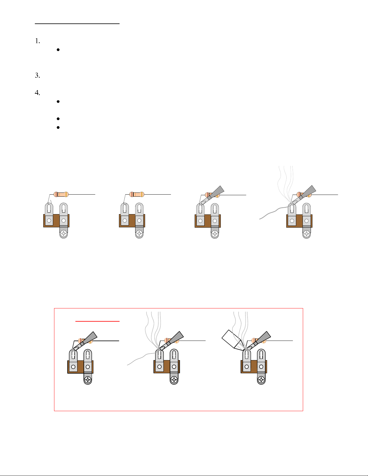
1. Bend the component lead
and rap it around the
connection point.
2. Wrap the component lead
so that it can hold itself to the
connection point.
3. Heat up both component
lead and connection point ith
the soldering iron.
4. Apply solder to both
component lead and
connection point.
2. Apply fresh solder to mix in
ith old solder joint
1. Heat up old solder joint
ith the soldering iron.
3. Use a de-soldering tool to
remove the old solder joint
hile it is heated.
De-Soldering Tip
8

UNPLUG
ON STANDBY
OFF
COOL
Preliminaries
lease make sure you do the following before opening your amp:
Unplug the power cord.
Turn the power switch off.
Turn the standby switch off (down position).
Give the power tubes 10 minutes to cool down.
Make sure the power tubes have cooled down enough to touch.
Remove all of the tubes from the amp and store them someplace safe.
Remove the amplifier chassis from its cabinet and set it on a safe workplace.
ON STANDBY
When the amp is open:
Follow the one hand
rule and use a volt meter with
alligator clips to measure for
high voltage at several test
points.
The one hand rule (pictured above): is a safety precaution for working on an amp that is
plugged in or could potentially have high voltages present. Using alligator clips with your
DMM, clip the ground side to the chassis and use the other side to probe at various test points
with one hand. This prevents a fatal shock which can result from current passing through the
heart. (Many people even put their other hand in their pocket or behind their back).
(test points are on the next page)
9

Test Points
If there is a high voltage present at any of these test points, there may be something
wrong with your amp. lease have it checked by a qualified repair shop.
TP(1), TP(2): These test points are both on the standby switch. When the amp is in
operation, these two points have a very high voltage present. By 10 minutes after
turning off the standby and power switches, all the voltage should have been drained.
TP(3): This is the anode side of a solid state diode.
TP(4), TP(5): These test points are the cathode pins of the preamp tubes. It is not a
bad idea to check these two pins on each one of the preamp tubes.
(Tube Rectifier TP: If your amp has a GZ34/5AR4 tube and no standby switch, then
check the GZ34 pins 2 and 8 for voltage.)
1
7
6
5
4
3
2
8
9
VOL
TREB
BASS
1
7
6
5
4
3
2
8
1.5K
470
1
7
6
5
4
3
2
8
470
1.5K
NORMAL
21
BRIGHT
MASTER
VOLUME
Je el
Lamp
Holder
POWER STANDBY
TP(1)
TP(2)
TP(3)
TP(4)
TP(5)
470
Inside View of Amp Chassis - not all components are shown
10

1
7
6
5
4
3
2
8
9
1
7
6
5
4
3
2
8
1
7
6
5
4
3
2
8
9
1
7
6
5
4
3
2
8
9
7025/12AX7
7025/12AX712AT7
V1V2V3V4
1st POWER TUBE
Circuit Board
To Phase Inverter To “Normal” Input To “Bass” Input
(STYLE-A)
1
7
6
5
4
3
2
8
9
1
7
6
5
4
3
2
8
1
7
6
5
4
3
2
8
9
1
7
6
5
4
3
2
8
9
7025/12AX7
7025/12AX7
V1V2V3V5
1st POWER TUBE
Circuit Board
To “Normal” Input To “Bass” Input
1
7
6
5
4
3
2
8
9
12AT7
V4
To Phase Inverter
7025/12AX7
(STYLE-B)
STYLE A (follow pages 12 – 17)
We define this style of amp as having the following characteristics:
a) The amp has 3 preamp tubes including two 7025/12AX7 tubes and one 12AT7 tube.
b) The first tube is connected to the “Bass” channel input.
c) The second tube is connected to the “Normal” input.
d) The third tube is the 12AT7 (phase inverter).
STYLE B (follow pages 18 – 23)
We define this style of amp as having the following characteristics:
a) The amp has 4 preamp tubes including three 7025/12AX7 tubes and one 12AT7 tube.
b) The first tube is connected to the “Bass” channel input.
c) The third tube is connected to the “Normal” channel input.
d) The fourth tube is the 12AT7 (phase inverter).
Step 1: Determine which style of Bassman you have.
Bass to Tremolo Modification
11

Bass to Tremolo Modification Schematic (STYLE-A)
Here is a schematic representation of this mod for style A amps. It is not necessary to be able to read the schematic in
order to complete the mod.
1
2
3
V2
1M
68K
68K
+
1.5K 25µ
100K
100K
250p
.047µ
.1µ
10KA
MIDDLE
250KA
BASS
250KA
TREB
1MA
VOL
6
7
8
V2
+
820
5µ
BRIGHT
120p
100K
220K .022µ
1MA
MSTR
.01µ
2
1
NORMAL TO V3
(PHASE
INVERTER)
1
2
3
V1
1M
68K
68K
+
1.5K
5µ
100K
100K
500p
.047µ
.1µ
8.2K
250KA
BASS
250KA
TREB
1MA
VOL
6
7
8
V1
DEEP
100K
375 VDC
220K
2
1
BASS
.047µ
1M
375 VDC
FENDER®BASSMAN 100 PREAMP
(BEFORE MODIFICATION)
.047µ
.0047µ
1
2
3
V2
1M
68K
68K
+
1.5K 25µ
100K
100K
250p
.047µ
.1µ
250KA
BASS
250KA
TREB
1MA
VOL
6
7
8
V2
+
1.5K
5µ
BRIGHT
120p
100K
220K .022µ
1MA
MSTR
.01µ
2
1
NORMAL TO V3
(PHASE
INVERTER)
375 VDC
FENDER®BASSMAN 100 PREAMP
(AFTER MODIFICATION)
.047µ
1
2
3
V1
+
2.7K
22µ
220K
6
7
8
V1
+
100K 22µ
8.2M
450 VDC
100K
.01µ
1M
1M
3M-RA
SPEED
100K
.01µ
.02µ
FOOT
SWITCH 3M
TREM
FROM BIAS TAP
50K-RA
INTENSITY
.1µ
470
- 9 VDC
10KA
MIDDLE
12

1
7
6
5
4
3
2
8
9
1
7
6
5
4
3
2
8
9
V1V2
+++
VOL
TREB
BASS
DEEP BASS
2 1
Step 2: Disconnect the “Bass” channel
front panel controls and wires.
(Save the components and wire that you
remove, in case you want to revert back
to a bass channel in the future).
Front Panel Controls to Remove
1) Disconnect and remove the wire connecting
the bass input to V1 pin 2.
2) Disconnect the deep switch connections to the
circuit board and ground.
3) Disconnect the resistor from the deep switch.
4) Disconnect the volume pot connection at V1
pin 7.
5) Disconnect the volume pot ground
connection.
6) Disconnect the capacitor from the volume
pot.
7) Disconnect the treble pot connection to the
board.
8) Disconnect the bass pot connections to the
board.
9) Disconnect the resistor from the bass pot.
Depending upon which amp model you
have, the layout of components may vary
slightly. The main idea of this step is to
remove the bass channel controls so that
we can mount the tremolo controls.
1
7
6
5
4
3
2
8
9
1
7
6
5
4
3
2
8
9
V1V2
+++
VOL
TREB
BASS
DEEP BASS
2 1
13

BASS
2 1
FOOTSWITCH
3
M
EG
5
0K
SPEED
INTENSITY
100K
.022µF
30V
DEEP BASS
2 1
VOL
TREB
BASS
1
7
6
5
4
3
2
8
9
1
7
6
5
4
3
2
8
9
V1V2
+++
Step 3: Remove the bass channel
controls from the front panel.
1) Deep switch
2) Volume pot
3) Treble pot
4) Bass pot
DEEP
VOLUMETREBLE
MIDDLE
BASS
TREMOLO
SPEED
INTENSITYBASS
FOOT
SWITCH
Step 3 (MID version): If your bass
channel has a mid control, leave the
last of the four pots mounted, but
completely disconnect it from the
circuit.
Disconnected
1
7
6
5
4
3
2
8
9
1
7
6
5
4
3
2
8
9
V1V2
+++
Step 4: Mount new front panel
controls for tremolo circuit
1) D DT slide switch
2) 3MΩ pot in place of the volume pot
3) 50kΩ pot in place of the treble pot
4) ¼” input jack in place of the bass pot
Step 5: Make preliminary front panel
control connections.
5) Connect the Tremolo switch ground as shown.
6) Connect a 100K resistor from ground to the
3M pot “cold” and “wiper” lugs.
7) Connect the footswitch jack “tip” lug to the
tremolo switch as shown.
8) Connect the footswitch jack “sleeve” lug to
the 50K pot “cold” lug.
9) Connect a .022µF cap from Tremolo switch to
3M pot “hot” lug as shown (leave the switch lug
unsoldered for now – there will be a wire
connected here later).
“sleeve”
(ground) “tip”
“cold”
“ iper”
“hot”
14

BASS
2 1
FOOTSWITCH
3
M
EG
5
0K
SPEED
INTENSITY
100K
.022µF
30V
1
7
6
5
4
3
2
8
9
1
7
6
5
4
3
2
8
9
V1V2
++
Step 6: Remove unnecessary circuit board
components.
1) Remove the cathode bias components connected to
V1 pin 3.
2) Remove the bass channel tone-stack components.
3) Remove the plate resistor connected to V1 pin 1.
4) Remove the plate resistors connected to V1 pin 6
and their connection to the 375V power supply.
5) Remove the jumper wire that was connect the V1
pin 6 plate resistor to the V2 pin 6 plate resistor.
6) Remove the shared cathode resistor connected to
V2 pin 8.
7) Remove the common cathode jumper wire
connected from V1 pin 8 to V2 pin 8.
Each instruction line number here corresponds to the
numbers on the drawing where missing components are
outlined.
(1)
(1)
(2)
(2)
(2) (2)
(2)
(3)(4)
(4)
375V Po er
Supply Line
(4)
(4)
(7)
(7)
(5)
(5)
BASS
2 1
FOOTSWITCH
3
M
EG
5
0K
SPEED
INTENSITY
100K
.022µF
30V
1
7
6
5
4
3
2
8
9
1
7
6
5
4
3
2
8
9
V1V2
++
Step 7: Add new circuit board
components.
1) Connect new cathode bias components (22µF
cap and 2.7K resistor) to V1 pin 3.
2) Connect a new cathode resistor (1.5K) to V2 pin
8.
3) Connect a new plate resistor (220K) to V1 pin 1.
4) Connect a new plate resistor (8.2M) to V1 pin 6.
5) Add the two .01µF feedback capacitors as
shown.
Positive
22µF 5 V
Negative
Connect these
polarized capacitors
ith the positive
lead connected to
the tube as sho n.
2.7K
22µF 5 V
+
220K
8.2M
.01µF
30V
.01µF
30V
(6)
1.5K
15

BASS
2 1
FOOTSWITCH
3
M
EG
5
0K
SPEED
INTENSITY
100K
.022µF
30V
1
7
6
5
4
3
2
8
9
1
7
6
5
4
3
2
8
9
V1V2
++
2.7K
22µF 5 V
+
220K
8.2M
.01µF
30V
.01µF
30V
Step 8: Mount the three terminal strips.
1) Mount T1 on a screw near the footswitch jack.
2) Mount T2 using the fiber board screw.
3) Mount T3 on a screw near V2.
Fasten the three terminal strips to existing
screws in the chassis as shown and in
similar locations.
Alternate
mounting method
See Terminal Strip Mounting
Section (p. 24)
Note: Terminal strip terminals will be referred to in a
shortened notation where T2(3) means terminal
number 3 on “T2”.
1 2 3 4 5
T2
100K
T3
T2
T1
Step 9: Add the components to each terminal strip.
1M 1M
3M
1 2
4 5
1) Connect the 3M resistor from terminal #1 to #4.
2) Connect a 1M resistor from terminal #2 to #4.
3) Connect a 1M resistor from terminal #4 to #5.
TOP VIEW SIDE VIEW
4) Connect the opto-coupler as shown. Make sure the two leads coming out of the
end marked with the dot are connected to terminals #1 and #2. The two leads
coming out of the unmarked end should be connected to terminals #3 and #5.
1
2
3
4
5
5) Connect a 100K resistor from terminal #2 to #4.
6) Connect a .1µF capacitor from terminal #1 to #5.
7) Connect a 22 F 50V capacitor with (-) side to terminal #3 and (+) side to terminal #4.
8) Connect a 100K resistor from terminal #3 to terminal #4.
Be careful not turn burn nearby components or wires with your soldering iron.
RESISTIVE SIDE IS
INDICATED ONLY
BY SLIGHTLY
SHORTER LEADS
NON-POLARIZED OPTICAL
SIDE IS INDICATED BY
SILVER DOT AND SLIGHTLY
LONGER LEADS
T1
T2
T3
100K
1.5K
.1µF
30V
1 5
22µF 5 V
100K
1

bias diode – not sho n
in actual location
1
7
6
5
4
3
2
8
1.5K
470
power tube socket – not
dra n to scale or in
actual location
AnodeCathode
BASS
2 1
FOOTSWITCH
3
M
EG
5
0K
SPEED
INTENSITY
100K
.022µF
30V
1
7
6
5
4
3
2
8
9
1
7
6
5
4
3
2
8
9
V1V2
++
2.7K
22µF 5 V
+
220K
8.2M
.01µF
30V
.01µF
30V
T1
T2
T3
10µF 1 V
+
1.5K
Step 1 : Wire it up.
Front Panel Controls
1) Connect the footswitch Jack “tip” lug to T1(4).
2) Connect the 50K pot “wiper” lug to T2(5).
3) Connect the 50K pot “hot” lug to T3(1).
4) Connect the 3M pot “hot” lug to one of the .01µF feedback capacitors as shown.
5) Connect the switch side of the .022µF front panel capacitor to the circuit board where V1 pin 1 is connected. In
some amps, it is important to run the path of this wire very close to the chassis and circuit board.
V1 Connections
1) Connect V1 pin 2 to the other .01µF feedback capacitor on the circuit board.
2) Connect that V1 pin 2 connection on the circuit board to T1(2).
3) Connect V1 pin 7 with two wires to T1(5) and the circuit board where the two .01µF feedback capacitors are connected together.
4) Connect V1 pin 8 to T3(4).
Circuit Board Connections
1) Connect T2(1) to the 8.2M resistor where it connects to V1 pin 6 on the board as shown.
2) Connect T2(4) to the circuit board where the 8.2M and 220K resistors connect.
3) Remove the one end of the 220K resistor from it’s board connection with V2 pin 6 and connect a wire from this end to T3(1).
4) Connect a wire from the circuit board connection with V2 pin 6 to T3(5).
Power Supply Connections
1) Connect the anode side of the solid state bias supply diode to T1(1).
2) Connect pin 6 from the closest octal power tube socket to the circuit board where the 8.2M and 220K resistors connect.
Step 11: After wiring any circuit, it is a good idea to double check your work.
If you have double checked your connections and are still having problems getting the tremolo effect to work, send an e-mail to
info@modkitsdiy.com.
Due to the nature of this circuit, there may be some audible clocking noise present.
“sleeve”
(ground) “tip”
“cold”
“ iper”
“hot”
1M
3M
1
5
1M
100K
.1µF
30V
15
22µF 5 V
100K
5
1
220K
17

Bass to Tremolo Modification Schematic (STYLE-B)
Here is a schematic representation of this mod for style B amps. It is not necessary to be able to read the schematic in
order to complete the mod.
1
2
3
V3
1M
68K
68K
+
1.5K 25µ
100K
500p
100K
250p
.047µ
.1µ
6.8K
250KA
BASS
250KA
TREB
1MA
VOL
6
7
8
V3
+
1.5K
25µ
BRIGHT
120p
100K
470K
220K
.01µ6
7
8
V2
+
1.5K25µ
100K
.01µ
1MA
MSTR
.01µ
220p
2
1
NORMAL TO V4
(PHASE
INVERTER)
1
2
3
V1
1M
68K
68K
+
1.5K
750µ
100K
100K
330p
.1µ
.047µ
8.2K
250KA
BASS
250KA
TREB
1MA
VOL
6
7
8
V1
+
1.5K
5µ
DEEP
100K
400 VDC
220K
2
1
BASS
.01µ
.1µ
220K
400 VDC
1
2
3
V1
+
2.7K
22µ
220K
6
7
8
V1
+
100K 22µ
8.2M
500 VDC
100K
.01µ
1M
1M
3M-RA
SPEED
100K
.01µ
.02µ
FOOT
SWITCH 3M
TREM
FROM BIAS TAP
50K-RA
INTENSITY
1
2
3
V3
1M
68K
68K
+
1.5K 25µ
100K
500p
100K
250p
.047µ
.1µ
6.8K
250KA
BASS
250KA
TREB
1MA
VOL
6
7
8
V3
+
1.5K
25µ
BRIGHT
120p
100K
470K .01µ6
7
8
V2
+
1.5K25µ
100K
.01µ
1MA
MSTR
.01µ
220p
2
1
NORMAL TO V4
(PHASE
INVERTER)
400 VDC
220K
220K
.1µ
FENDER®BASSMAN 70 PREAMP
(BEFORE MODIFICATION)
FENDER®BASSMAN 70 PREAMP
(AFTER MODIFICATION)
1.2K
- 0 VDC
18

1
7
6
5
4
3
2
8
9
1
7
6
5
4
3
2
8
9
V1V2
VOL
TREBBASS
DEEP BASS
2 1
1
7
6
5
4
3
2
8
9
1
7
6
5
4
3
2
8
9
V3V4
Step 2: Disconnect the “Bass” channel
front panel controls and wires.
(Save the components and wire that you
remove, in case you want to revert back
to a bass channel in the future).
Front Panel Controls to Remove
1) Disconnect and remove the wire connecting
the bass input to V1 pin 2.
2) Disconnect the deep switch connections to the
circuit board and ground.
3) Disconnect the volume pot connection at V1
pin 7.
4) Disconnect the volume pot ground
connection.
5) Disconnect the treble pot connection to the
board.
6) Disconnect the bass pot connections to the
board.
7) Disconnect the resistor from the bass pot.
Depending upon which amp model you
have, the layout of components may vary
slightly. The main idea of this step is to
remove the bass channel controls so that
we can mount the tremolo controls.
1
7
6
5
4
3
2
8
9
1
7
6
5
4
3
2
8
9
V1V2
VOL
TREB
BASS
DEEP BASS
2 1
1
7
6
5
4
3
2
8
9
1
7
6
5
4
3
2
8
9
V3V4
19

Step 3: Remove the bass channel
controls from the front panel.
1) Deep switch
2) Volume pot
3) Treble pot
4) Bass pot
Step 4: Mount new front panel
controls for tremolo circuit
1) D DT slide switch
2) 3MΩ pot in place of the volume pot
3) 50kΩ pot in place of the treble pot
4) ¼” input jack in place of the bass pot
1
7
6
5
4
3
2
8
9
1
7
6
5
4
3
2
8
9
V1V2
1
7
6
5
4
3
2
8
9
1
7
6
5
4
3
2
8
9
V3V4
(STYLE-B) DEEP BASS
2 1
VOLTREB
BASS
DEEP
VOLUME
TREBLEMIDDLEBASS
TREMOLO
SPEED
INTENSITYBASS
FOOT
SWITCH
Step 3 (MID version): If your bass
channel has a mid control, leave the
last of the four pots mounted, but
completely disconnect it from the
circuit.
Disconnected
BASS
2 1
FOOTSWITCH
3
M
EG
5
0K
SPEED
INTENSITY
1
7
6
5
4
3
2
8
9
1
7
6
5
4
3
2
8
9
V1V2
1
7
6
5
4
3
2
8
9
1
7
6
5
4
3
2
8
9
V3V4
Step 5: Make preliminary front panel
control connections.
5) Connect the Tremolo switch ground as shown.
6) Connect a 100K resistor from ground to the
3M pot “cold” and “wiper” lugs.
7) Connect the footswitch jack “tip” lug to the
tremolo switch as shown.
8) Connect the footswitch jack “sleeve” lug to
the 50K pot “cold” lug.
9) 9) Connect a .022µF cap from Tremolo switch
to 3M pot “hot” lug as shown (leave the switch
lug unsoldered for now – there will be a wire
connected here later).
100K
.022µF
30V
“sleeve”
(ground) “tip”
“cold”
“ iper”
“hot”
20
Table of contents