7
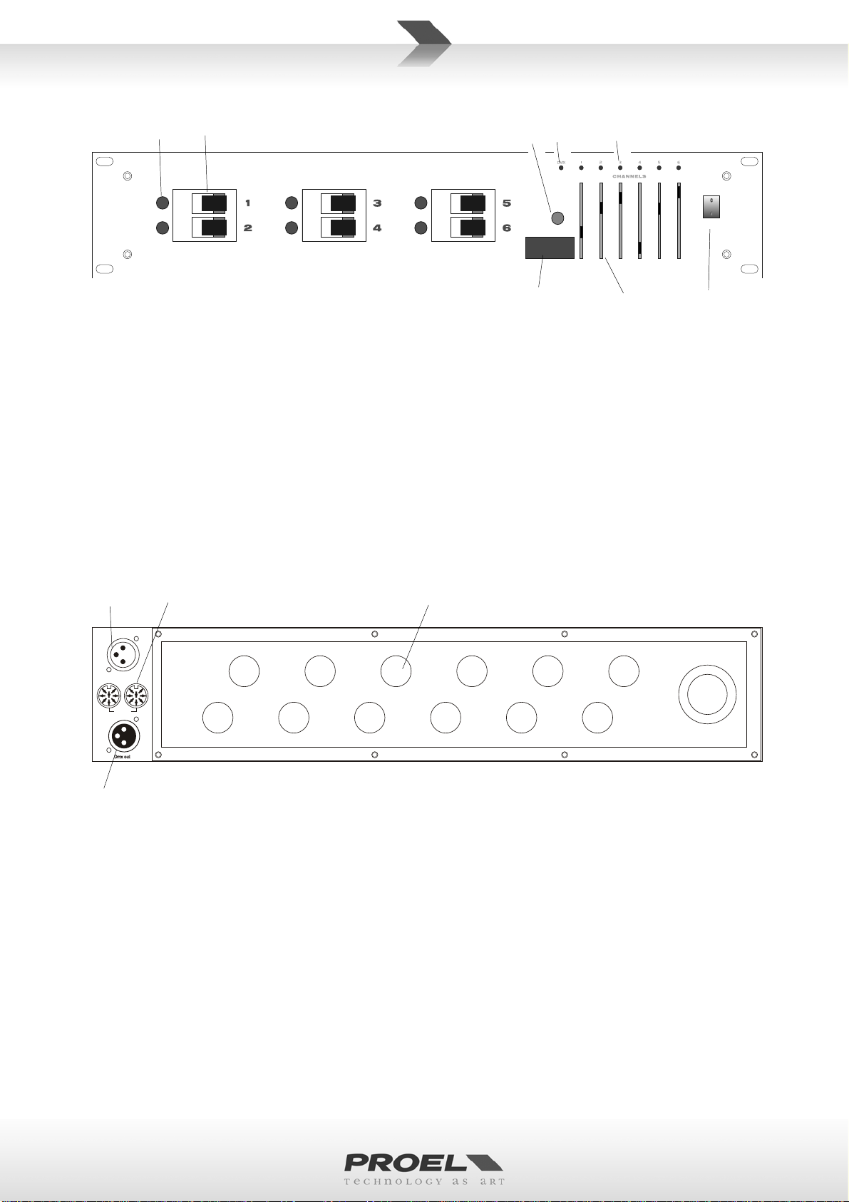
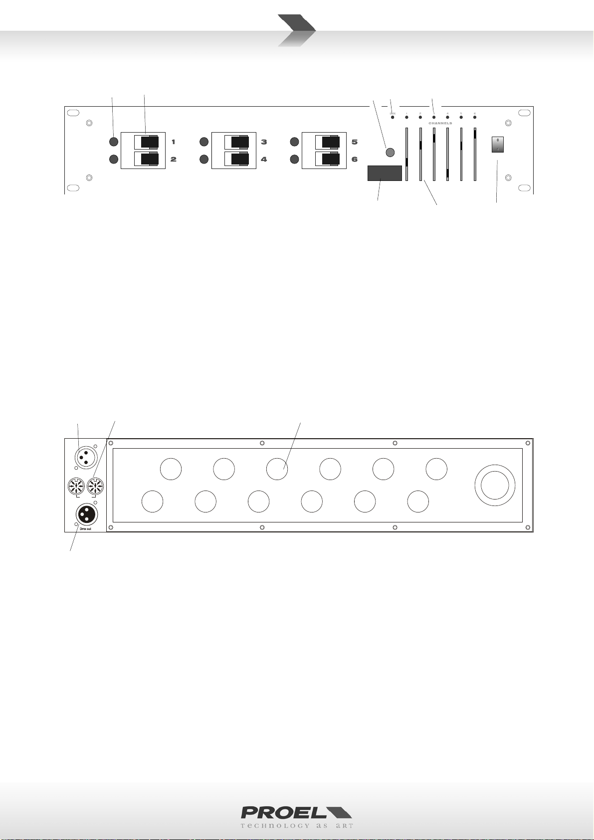
FRONT PANEL
POWER
DMX ADDRESS
1. Channel indicator (x6). These indicators are turned off without connecting load, they are turned on
when load is connected.
2. Circuit breaker (x6). This circuit breaker will cut off power supply automatically when load current
exceeds 10A.
3. Dip switch.These switches are set to select start DMX address.
4. PREHEAT control.This control adjust the initial lighting point.
5. DMX indicator.
6. Channel dimmer indicator (x6).
7. Channel dimmer control (x6).These controls adjust appropriate channel dimmer level.
8. Power switch.
REAR PANEL
Dmx out
Dmx in
Analog
1. DMX output socket. Use to connect to DMX input socket of next unit for parallel control.
2. DMX input socket. Use to connect to DMX input signals.
3. ANALOG input / output (8-pin din socket)
4. Output wiring port (x5). Use to connect to 6 channel output, 10A per channel max, total 60A max.
OPERATION
1. Please confirm power requirement is matched with that specified on this unit
2. Set up correct wire connections. (see connections diagram).
3. Apply to required control signals.
4. Check for proper wire connections, turn power switch on.
5. If PREHEAT control is set to maximum, channel dimmer level should be 50 percent of setting
maximum dimmer.
6. Receive DMX signals.
• Primarily, select initial channel to apply to DMX signals.
• Set dipswitch 10 to OFF, the system should receive 6 channel DMX signals and control 6 channel
output in sequence, how DMX indicator should turn on.
1 2
3
4 5 6
7 8
2
1
3 4