FTE
Indice
- Avvertenze . . . . . . . . . . . . . . . . . . . . . . . . . . . . . . . . . . . . . . . . . . . . . . . . . . . . . . . . .2
- Applicazioni . . . . . . . . . . . . . . . . . . . . . . . . . . . . . . . . . . . . . . . . . . . . . . . . . . . . . . .2
- Ispezione, trasporto e movimentazione . . . . . . . . . . . . . . . . . . . . . . .2
- Installazione e messa in opera . . . . . . . . . . . . . . . . . . . . . . . . . . . . . . . . .2
- Manutenzione generale e controllo . . . . . . . . . . . . . . . . . . . . . . . . . . . .4
- Caratteristiche tecniche . . . . . . . . . . . . . . . . . . . . . . . . . . . . . . . . . . . . . . . . .4
- Pericoli . . . . . . . . . . . . . . . . . . . . . . . . . . . . . . . . . . . . . . . . . . . . . . . . . . . . . . . . . . . . .4
- Norme di riferimento . . . . . . . . . . . . . . . . . . . . . . . . . . . . . . . . . . . . . . . . . . . .4
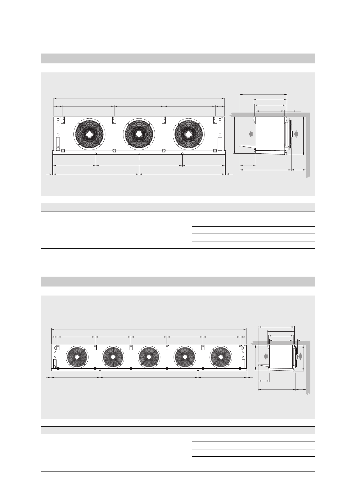
- Caratteristiche dimensionali . . . . . . . . . . . . . . . . . . . . . . . . . . . . . . . . . . . .5
- Caratteristiche tecniche . . . . . . . . . . . . . . . . . . . . . . . . . . . . . . . . . . . . . . . . .7
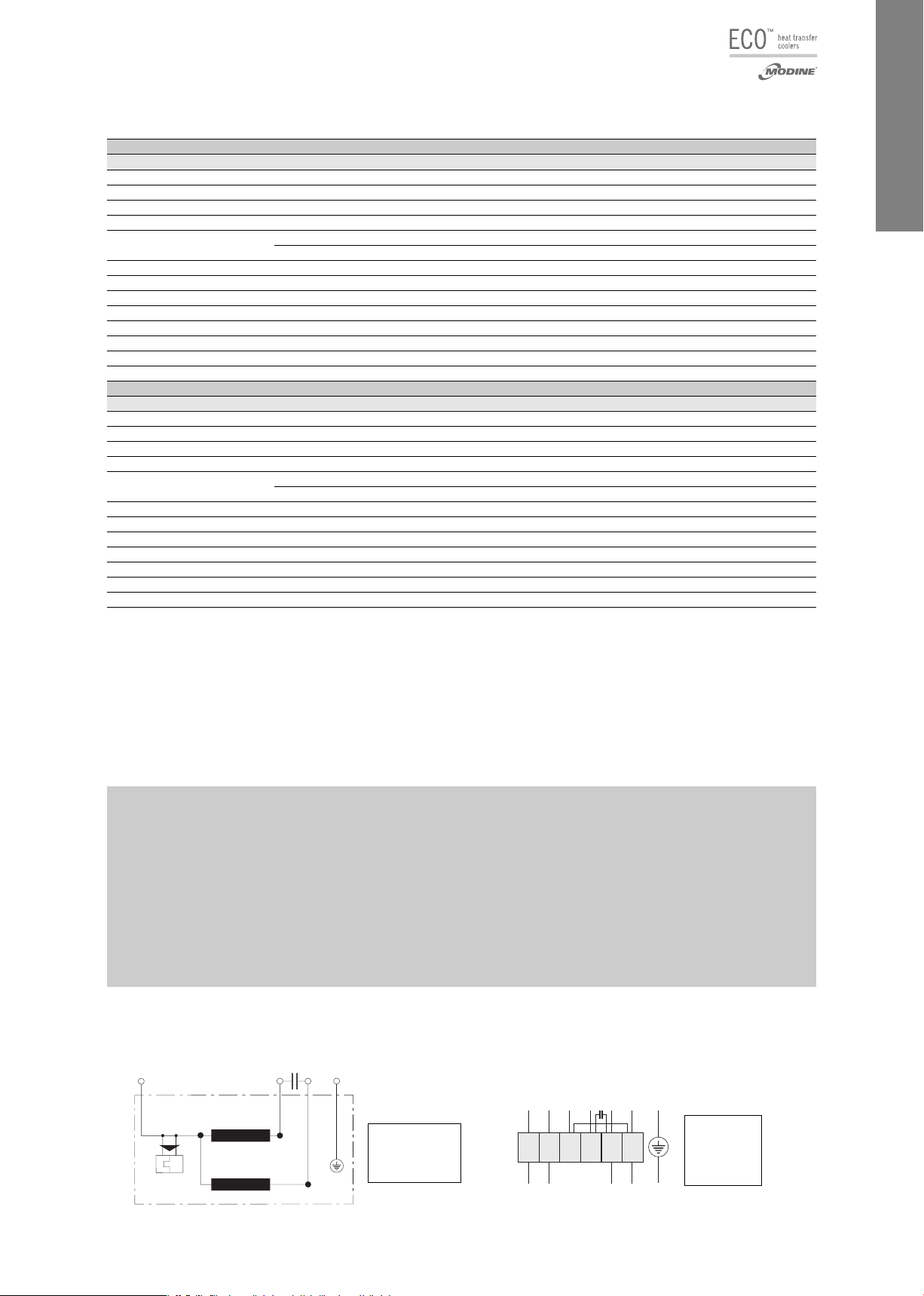
- Schemi di collegamento
e assorbimento dei motoventilatori . . . . . . . . . . . . . . . . . . . . . . . . . . . .7
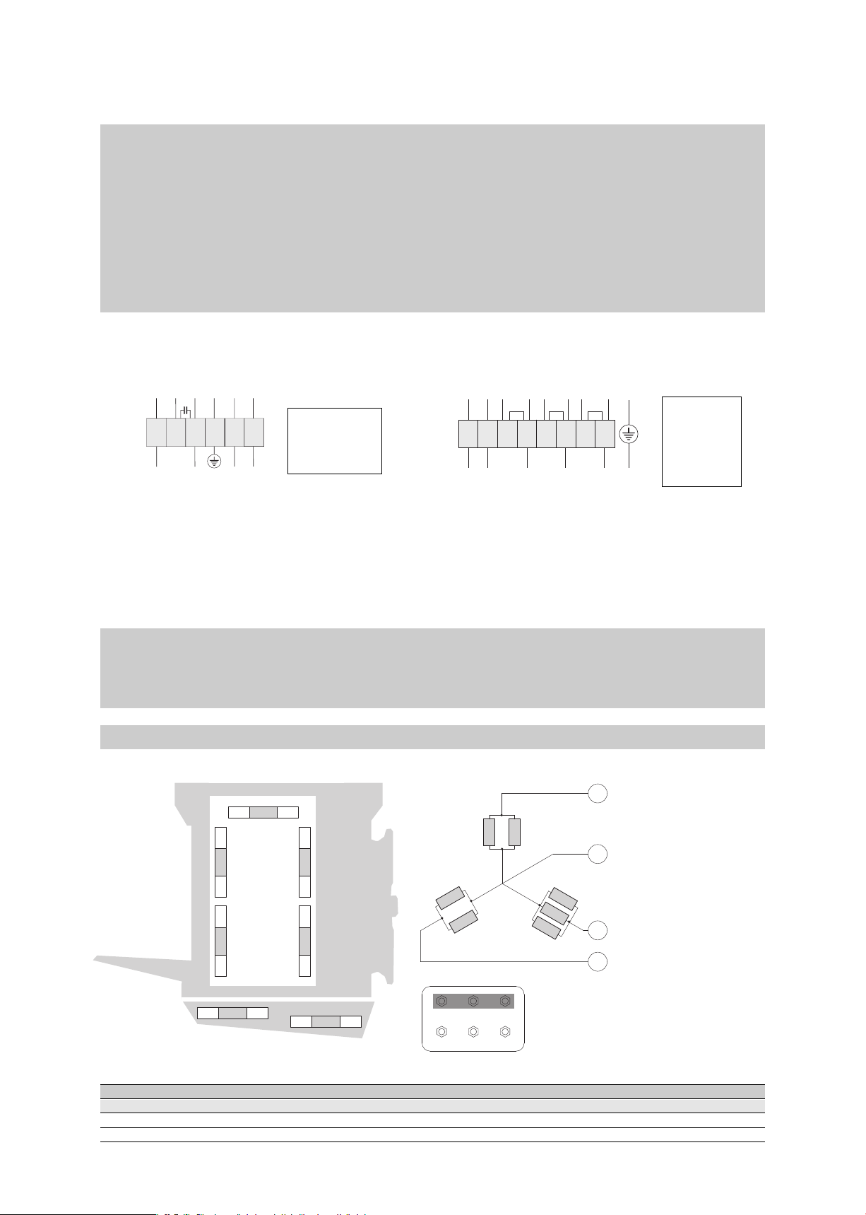
- Schemi di collegamento
e potenze delle resistenze elettriche . . . . . . . . . . . . . . . . . . . . . . . . . .8
- Garanzie . . . . . . . . . . . . . . . . . . . . . . . . . . . . . . . . . . . . . . . . . . . . . . . . . . . . . . . . . .51
Index
- Important . . . . . . . . . . . . . . . . . . . . . . . . . . . . . . . . . . . . . . . . . . . . . . . . . . . . . . . .10
- Applications . . . . . . . . . . . . . . . . . . . . . . . . . . . . . . . . . . . . . . . . . . . . . . . . . . . . .10
- Inspection, transportation, handling . . . . . . . . . . . . . . . . . . . . . . . .10
- Installation and set-up . . . . . . . . . . . . . . . . . . . . . . . . . . . . . . . . . . . . . . . . .10
- General maintenance & control . . . . . . . . . . . . . . . . . . . . . . . . . . . . . .11
- Technical features . . . . . . . . . . . . . . . . . . . . . . . . . . . . . . . . . . . . . . . . . . . . . .12
- Hazards / Risks . . . . . . . . . . . . . . . . . . . . . . . . . . . . . . . . . . . . . . . . . . . . . . . . .12
- Reference standards . . . . . . . . . . . . . . . . . . . . . . . . . . . . . . . . . . . . . . . . . . .12
- Dimensional features . . . . . . . . . . . . . . . . . . . . . . . . . . . . . . . . . . . . . . . . . .13
- Technical features . . . . . . . . . . . . . . . . . . . . . . . . . . . . . . . . . . . . . . . . . . . . . .15
- Connection scheme and fan motor absorption . . . . . . . . . . . . .15
- Electric heater connection scheme
and electric power . . . . . . . . . . . . . . . . . . . . . . . . . . . . . . . . . . . . . . . . . . . . . .16
- Warranty . . . . . . . . . . . . . . . . . . . . . . . . . . . . . . . . . . . . . . . . . . . . . . . . . . . . . . . . . .51
Index
- Hinweise . . . . . . . . . . . . . . . . . . . . . . . . . . . . . . . . . . . . . . . . . . . . . . . . . . . . . . . . .18
- Anwendungen . . . . . . . . . . . . . . . . . . . . . . . . . . . . . . . . . . . . . . . . . . . . . . . . . . .18
- Kontrolle - Transport - Psitionieren . . . . . . . . . . . . . . . . . . . . . . . . . .18
- Aufstellung und Inbetriebnahme . . . . . . . . . . . . . . . . . . . . . . . . . . . . .18
- Allgemeine Wartung und Kontrolle . . . . . . . . . . . . . . . . . . . . . . . . . .19
- Technische Eigenschaften . . . . . . . . . . . . . . . . . . . . . . . . . . . . . . . . . . . .20
- Gefahren . . . . . . . . . . . . . . . . . . . . . . . . . . . . . . . . . . . . . . . . . . . . . . . . . . . . . . . . .20
- Bezugsnormen . . . . . . . . . . . . . . . . . . . . . . . . . . . . . . . . . . . . . . . . . . . . . . . . . .20
- Dimensionale Eigenschaften . . . . . . . . . . . . . . . . . . . . . . . . . . . . . . . . . .21
- Technische Eigenschaften . . . . . . . . . . . . . . . . . . . . . . . . . . . . . . . . . . . .23
- Anschlußplan und Stromaufnahme
der Motorventilatoren . . . . . . . . . . . . . . . . . . . . . . . . . . . . . . . . . . . . . . . . . .23
- Anschlußplan und Leistungen der Heizstäbe . . . . . . . . . . . . . .24
- Gewährleistung . . . . . . . . . . . . . . . . . . . . . . . . . . . . . . . . . . . . . . . . . . . . . . . . . .51
Indice
- Advertencias . . . . . . . . . . . . . . . . . . . . . . . . . . . . . . . . . . . . . . . . . . . . . . . . . . . . .26
- Aplicaciones . . . . . . . . . . . . . . . . . . . . . . . . . . . . . . . . . . . . . . . . . . . . . . . . . . . . .26
- Inspección transporte y manejo . . . . . . . . . . . . . . . . . . . . . . . . . . . . . .26
- Instalación y puesta en marcha . . . . . . . . . . . . . . . . . . . . . . . . . . . . . .26
- Mantenimiento general y control . . . . . . . . . . . . . . . . . . . . . . . . . . . . .27
- Características técnicas . . . . . . . . . . . . . . . . . . . . . . . . . . . . . . . . . . . . . . .28
- Peligros . . . . . . . . . . . . . . . . . . . . . . . . . . . . . . . . . . . . . . . . . . . . . . . . . . . . . . . . . . .28
- Normas de referencia . . . . . . . . . . . . . . . . . . . . . . . . . . . . . . . . . . . . . . . . . .28
- Características dimensionales . . . . . . . . . . . . . . . . . . . . . . . . . . . . . . . .29
- Características técnicas . . . . . . . . . . . . . . . . . . . . . . . . . . . . . . . . . . . . . . .31
- Esquema de conexión
y absorción motoventiladores . . . . . . . . . . . . . . . . . . . . . . . . . . . . . . . . .31
- Esquema de conexión y potencia
de las resistencias eléctricas . . . . . . . . . . . . . . . . . . . . . . . . . . . . . . . . .32
- Garantías . . . . . . . . . . . . . . . . . . . . . . . . . . . . . . . . . . . . . . . . . . . . . . . . . . . . . . . . .51
Index
- Attention . . . . . . . . . . . . . . . . . . . . . . . . . . . . . . . . . . . . . . . . . . . . . . . . . . . . . . . . .34
- Applications . . . . . . . . . . . . . . . . . . . . . . . . . . . . . . . . . . . . . . . . . . . . . . . . . . . . .34
- Inspection, transport et déplacement . . . . . . . . . . . . . . . . . . . . . . .34
- Installation et mise en marche . . . . . . . . . . . . . . . . . . . . . . . . . . . . . . .34
- Entretien général et contrôle . . . . . . . . . . . . . . . . . . . . . . . . . . . . . . . . .35
- Caractéristiques techniques . . . . . . . . . . . . . . . . . . . . . . . . . . . . . . . . . .36
- Dangers . . . . . . . . . . . . . . . . . . . . . . . . . . . . . . . . . . . . . . . . . . . . . . . . . . . . . . . . . .36
- Normes de référence . . . . . . . . . . . . . . . . . . . . . . . . . . . . . . . . . . . . . . . . . . .36
- Caractéristiques dimensionnelles . . . . . . . . . . . . . . . . . . . . . . . . . . . .37
- Caractéristiques techniques . . . . . . . . . . . . . . . . . . . . . . . . . . . . . . . . . .39
- Schéma de connexion
et absorptions motoventilateurs . . . . . . . . . . . . . . . . . . . . . . . . . . . . . .39
- Schéma de connexion et puissances
des résistances électriques . . . . . . . . . . . . . . . . . . . . . . . . . . . . . . . . . . .40
- Garantie . . . . . . . . . . . . . . . . . . . . . . . . . . . . . . . . . . . . . . . . . . . . . . . . . . . . . . . . . .51
Указатель
- Меры предосторожности . . . . . . . . . . . . . . . . . . . . . . . . . . . . . . . . . . . . . . 42
- Область применения . . . . . . . . . . . . . . . . . . . . . . . . . . . . . . . . . . . . . . . . . . . . 42
- Осмотр, транспортировк а и перемещение . . . . . . . . . . . . . 42
- Установка и пуск в эксплуатацию . . . . . . . . . . . . . . . . . . . . . . . . . 42
- Общее техобслуживание и контроль . . . . . . . . . . . . . . . . . . . . . 44
- Технические характеристики . . . . . . . . . . . . . . . . . . . . . . . . . . . . . . . . 44
- Опасность . . . . . . . . . . . . . . . . . . . . . . . . . . . . . . . . . . . . . . . . . . . . . . . . . . . . . . . . . . . 44
- Нормативная документация . . . . . . . . . . . . . . . . . . . . . . . . . . . . . . . . . 44
- Габаритные характеристики . . . . . . . . . . . . . . . . . . . . . . . . . . . . . . . . . 45
- Технические характеристики . . . . . . . . . . . . . . . . . . . . . . . . . . . . . . . . 47
- Схемы подключения и потребления
электровентиляторов . . . . . . . . . . . . . . . . . . . . . . . . . . . . . . . . . . . . . . . . . . 47
- Схемы подключения и мощностей
электрических ТЭНов . . . . . . . . . . . . . . . . . . . . . . . . . . . . . . . . . . . . . . . . . . 48
- Гарантии . . . . . . . . . . . . . . . . . . . . . . . . . . . . . . . . . . . . . . . . . . . . . . . . . . . . . . . . . . . . . .51
Index