manuals.online logo
Brands
  1. Home
  2. •
  3. Brands
  4. •
  5. Modine Manufacturing
  6. •
  7. Air Conditioner
  8. •
  9. Modine Manufacturing ECO GSE31AH4 User manual

Modine Manufacturing ECO GSE31AH4 User manual

MANUALE TECNICO
Aeroevaporatori a so󰀩tto
TECHNICAL MANUAL
Ceiling unit coolers
BETRIEBSANLEITUNG
Deckenluftverdampfer
MANUAL TECNICO
Aeroevaporadores de techo
MANUEL TECHNIQUE
Evaporateurs plafonniers
ТЕХНИЧЕСКОЕ РУКОВОДСТВО
Потолочные воздухоохладители
GSE
Index
www.modine.com 3
Indice - Istruzioni per l'uso originali
Versione linguistica originale
1. Importante . . . . . . . . . . . . . . . . . . . . . . . . . . . . . . . . . 5
2. Applicazioni . . . . . . . . . . . . . . . . . . . . . . . . . . . . . . . . 6
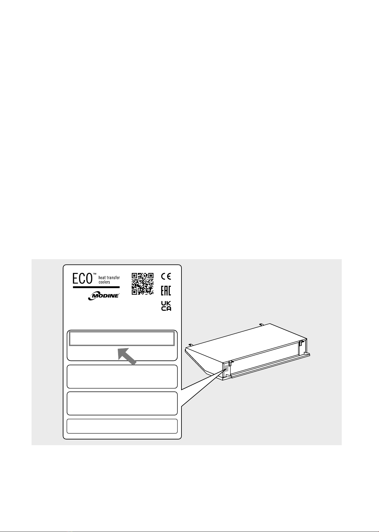
3. Identicazione . . . . . . . . . . . . . . . . . . . . . . . . . . . . . . . 6
4. Ispezione - Stoccaggio. . . . . . . . . . . . . . . . . . . . . . . . . . . 7
5. Movimentazione e installazione . . . . . . . . . . . . . . . . . . . . . . 7
6. Condizioni di installazione . . . . . . . . . . . . . . . . . . . . . . . . . 8
7. Caratteristiche costruttive e dimensionali . . . . . . . . . . . . . . . . 10
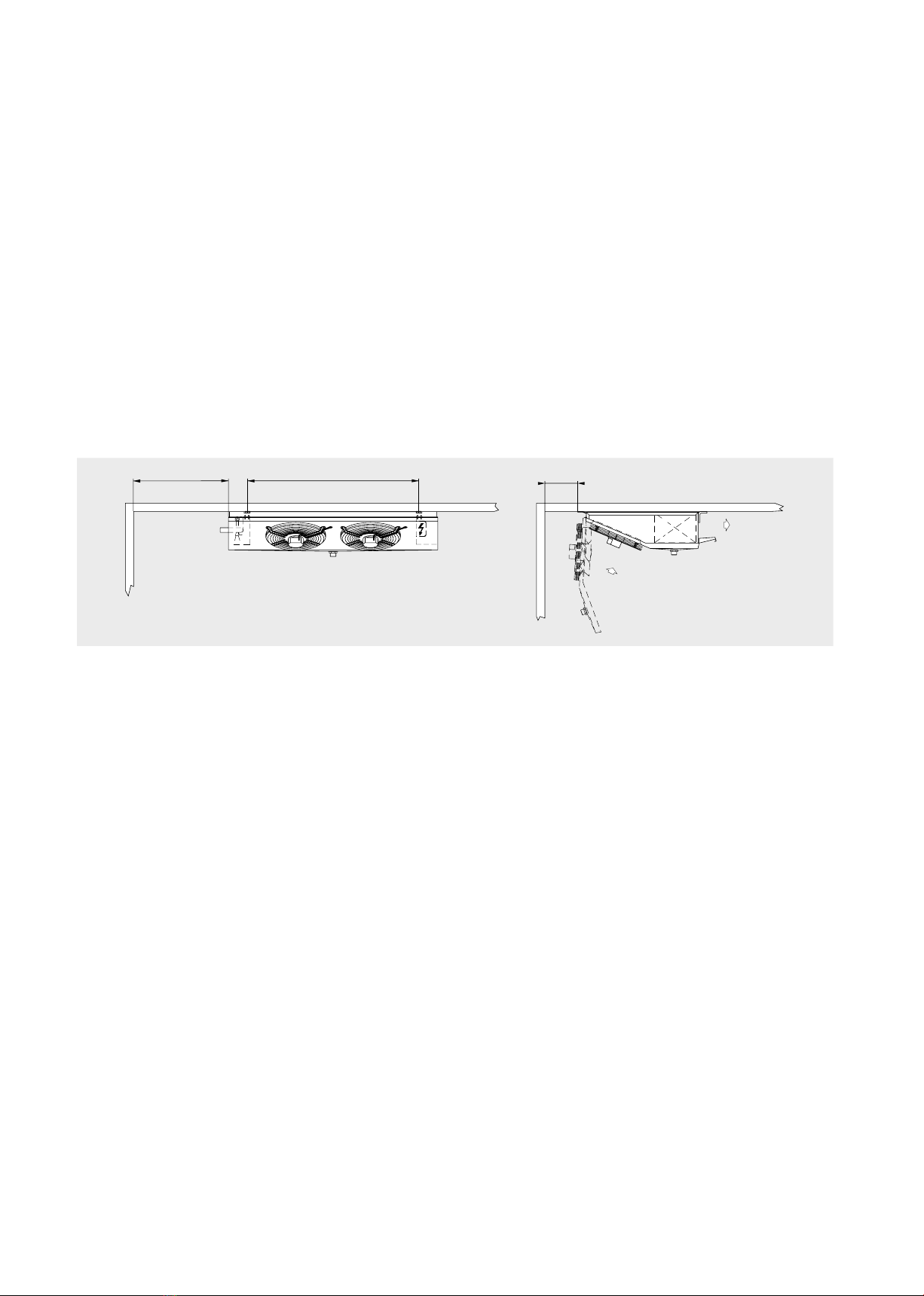
8. Suggerimenti per un corretto accesso all’unità . . . . . . . . . . . . . .11
9. Schemi elettrici. . . . . . . . . . . . . . . . . . . . . . . . . . . . . . 12
10. Controlli da eseguire prima della messa in funzione . . . . . . . . . . 14
11. Controlli dopo la messa in funzione . . . . . . . . . . . . . . . . . . . 14
12. Manutenzione . . . . . . . . . . . . . . . . . . . . . . . . . . . . . . 14
13. Rischi residui. . . . . . . . . . . . . . . . . . . . . . . . . . . . . . . 17
14. Norme e direttive di riferimento . . . . . . . . . . . . . . . . . . . . . 19
15. Dati tecnici . . . . . . . . . . . . . . . . . . . . . . . . . . . . . . . . 20
Dichiarazione di incorporazione – Garanzie . . . . . . . . . . . . . . .101
1. Important. . . . . . . . . . . . . . . . . . . . . . . . . . . . . . . . . 21
2. Applications . . . . . . . . . . . . . . . . . . . . . . . . . . . . . . . 22
3. Identication . . . . . . . . . . . . . . . . . . . . . . . . . . . . . . . 22
4. Inspection - Storage . . . . . . . . . . . . . . . . . . . . . . . . . . . 23
5. Handling and installation. . . . . . . . . . . . . . . . . . . . . . . . . 23
6. Installation conditions . . . . . . . . . . . . . . . . . . . . . . . . . . 24
7. Construction and dimensional features . . . . . . . . . . . . . . . . . 26
8. Recommendations for a proper access to the model . . . . . . . . . . 27
9. Wiring diagrams . . . . . . . . . . . . . . . . . . . . . . . . . . . . . 28
10. Checks to be performed before start-up . . . . . . . . . . . . . . . . . 30
11. Checks to be performed after start-up . . . . . . . . . . . . . . . . . . 30
12. Maintenance . . . . . . . . . . . . . . . . . . . . . . . . . . . . . . . 30
13. Residual risks . . . . . . . . . . . . . . . . . . . . . . . . . . . . . . 33
14. Reference standards and directives . . . . . . . . . . . . . . . . . . . 35
15. Technical data . . . . . . . . . . . . . . . . . . . . . . . . . . . . . . 36
Index - Translation of the original instructions
Declaration of incorporation – Warranties . . . . . . . . . . . . . . . . 101
1. Wichtig . . . . . . . . . . . . . . . . . . . . . . . . . . . . . . . . . . 37
2. Anwendungen . . . . . . . . . . . . . . . . . . . . . . . . . . . . . . 38
3. Identizierung . . . . . . . . . . . . . . . . . . . . . . . . . . . . . . 38
4. Inspektion - Lagerung . . . . . . . . . . . . . . . . . . . . . . . . . . 39
5. Handhabung und Montage . . . . . . . . . . . . . . . . . . . . . . . 39
6. Montagebedingungen . . . . . . . . . . . . . . . . . . . . . . . . . . 40
7. Konstruktionseigenschaften und Abmessungen. . . . . . . . . . . . . 42
8. Ratschläge für einen korrekten Zugang zum Gerät . . . . . . . . . . . 43
9. Elektrische Pläne . . . . . . . . . . . . . . . . . . . . . . . . . . . . 44
10. Kontrollen vor Inbetriebnahme. . . . . . . . . . . . . . . . . . . . . . 46
11. Kontrollen nach Inbetriebnahme. . . . . . . . . . . . . . . . . . . . . 46
12. Wartung . . . . . . . . . . . . . . . . . . . . . . . . . . . . . . . . . 46
13. Restrisiko . . . . . . . . . . . . . . . . . . . . . . . . . . . . . . . . 49
14. Bezugsnormen und Richtlinien . . . . . . . . . . . . . . . . . . . . . 51
15. Technische Daten . . . . . . . . . . . . . . . . . . . . . . . . . . . . 52
Index - Übersetzung der Originalanleitung
Einbauerklärung – Garantie . . . . . . . . . . . . . . . . . . . . . . . 101
1. Importante . . . . . . . . . . . . . . . . . . . . . . . . . . . . . . . . 53
2. Aplicaciones . . . . . . . . . . . . . . . . . . . . . . . . . . . . . . . 54
3. Identicación. . . . . . . . . . . . . . . . . . . . . . . . . . . . . . . 54
4. Inspección - Almacenamiento . . . . . . . . . . . . . . . . . . . . . . 55
5. Movilización e instalación . . . . . . . . . . . . . . . . . . . . . . . . 55
6. Condiciones de instalación . . . . . . . . . . . . . . . . . . . . . . . 56
7. Características constructivas y dimensionales . . . . . . . . . . . . . 58
8. Sugerencias para un correcto acceso al modelo . . . . . . . . . . . . 59
9. Esquemas eléctricos. . . . . . . . . . . . . . . . . . . . . . . . . . . 60
10. Controles antes de la puesta en funcionamiento . . . . . . . . . . . . 62
11. Controles después de la puesta en funcionamiento. . . . . . . . . . . 62
12. Mantenimiento . . . . . . . . . . . . . . . . . . . . . . . . . . . . . . 62
13. Riesgos restantes . . . . . . . . . . . . . . . . . . . . . . . . . . . . 65
14. Normas y directivas de referencia . . . . . . . . . . . . . . . . . . . . 67
15. Datos técnicos . . . . . . . . . . . . . . . . . . . . . . . . . . . . . . 68
Ìndice - Traducción de las instrucciones originales
Declaración de incorporación – Garantías. . . . . . . . . . . . . . . .101
1. Important. . . . . . . . . . . . . . . . . . . . . . . . . . . . . . . . . 69
2. Applications . . . . . . . . . . . . . . . . . . . . . . . . . . . . . . . 70
3. Identication . . . . . . . . . . . . . . . . . . . . . . . . . . . . . . . 70
4. Inspection - Stockage . . . . . . . . . . . . . . . . . . . . . . . . . . 71
5. Manutention et installation . . . . . . . . . . . . . . . . . . . . . . . . 71
6. Conditions d’installation . . . . . . . . . . . . . . . . . . . . . . . . . 72
7. Caractéristiques constructives et dimensionnelles . . . . . . . . . . . 74
8. Instructions pour accéder à l’appareil . . . . . . . . . . . . . . . . . . 75
9. Schémas électriques. . . . . . . . . . . . . . . . . . . . . . . . . . . 76
10. Contrôles à e󰀨ectuer avant la mise en marche . . . . . . . . . . . . . 78
11. Contrôles à e󰀨ectuer après la mise en marche . . . . . . . . . . . . . 78
12. Entretien/maintenance. . . . . . . . . . . . . . . . . . . . . . . . . . 78
13. Risques résiduels . . . . . . . . . . . . . . . . . . . . . . . . . . . . 81
14. Normes et directives de référence . . . . . . . . . . . . . . . . . . . . 83
15. Données techniques . . . . . . . . . . . . . . . . . . . . . . . . . . . 84
Déclaration d’incorporation – Garanties
Déclaration d’incorporation – Garanties . . . . . . . . . . . . . . . . . 101
1. Важно . . . . . . . . . . . . . . . . . . . . . . . . . . . . . . . . . . 85
2. Использование . . . . . . . . . . . . . . . . . . . . . . . . . . . . . 86
3. Идентификация . . . . . . . . . . . . . . . . . . . . . . . . . . . . . 86
4. Проверка - Хранение . . . . . . . . . . . . . . . . . . . . . . . . . . 87
5. Транспортировка и установка . . . . . . . . . . . . . . . . . . . . . 87
6. Условия установки . . . . . . . . . . . . . . . . . . . . . . . . . . . 88
7. Конструкция и габаритные характеристики . . . . . . . . . . . . . . 90
8. Рекомендации по корректному доступу к аппарату . . . . . . . . . 91
9. Схемы подключения . . . . . . . . . . . . . . . . . . . . . . . . . . 92
10. Контроль перед вводом в эксплуатацию . . . . . . . . . . . . . . . 94
11. Контроль после ввода в эксплуатацию . . . . . . . . . . . . . . . . 94
12. Техобслуживание . . . . . . . . . . . . . . . . . . . . . . . . . . . . 94
13. Остаточные риски . . . . . . . . . . . . . . . . . . . . . . . . . . . 97
14. Справочные стандарты и директивы . . . . . . . . . . . . . . . . . 99
15. Технические Данные . . . . . . . . . . . . . . . . . . . . . . . . . . 100
Содержание - Перевод оригинала инструкции
Декларация о включении – Гарантия . . . . . . . . . . . . . . . . . 101
www.modine.com20
15. Dati tecnici
15.1 Dati tecnici
15.2 Codice di identicazione
15.3 Documenti forniti con il modello o disponibili al seguente link: https://www.modinecoolers.com/documents/
15.3.1 Manuale Tecnico – Istruzioni per l'uso
15.3.2 Dichiarazione di incorporazione
15.3.3 Manuale d'uso dei ventilatori (quando previsto)
15.3.4 Schemi elettrici (quando previsti)
15.3.5 Manuali d'uso degli accessori (quando presenti)
Codice modello Etichetta sull’unità
Numero di serie Etichetta sull’unità
Anno di produzione Etichetta sull’unità
Pressione max PS Etichetta sull’unità
Numero di progetto Documenti relativi a o󰀨erta / ordine
Tipo di uido Documenti relativi a o󰀨erta / ordine
Volume interno Etichetta sull’unità
Peso Etichetta sull’unità
Livello di pressione sonora Documenti relativi a o󰀨erta / ordine
Corrente Etichetta sull’unità e Manuale tecnico Sez. 9
Tensione Etichetta sull’unità e Manuale tecnico Sez. 9
Serie Diametro
ventilatori
Numero
ventilatori
Ranghi Passo alette Sbrinamento
elettrico
Specialità
GSE 3 1 A H4 ED .1079
3 = Ø315 1A = 6 H4 = 4mm
[ED] = sbrinamento
elettrico opzionale
[.xxxx] = specialità
opzionali
2B = 8 L7 = 7mm
3
4
www.modine.com 21
English
1. Important
1.1 Carefully read all the information in this manual before removing the packaging, before handling, assembling, positioning,
commissioning of the machine and before performing any work on the model. If in doubt contact Modine.
1.2 This manual is an integral part of the product and must be kept for the entire life of the unit.
1.3 Modine declines all responsibility for damage to persons and property caused by failure to follow all instructions contained
in this manual.
1.4 The unit must only be used for the purpose for which it was expressly designed: improper use releases Modine from any
liability.
1.5 This manual must be kept available near the unit for the entire life of the same.
1.6 The use of uids or substances which could corrode, make unsafe or reduce the performance of the unit is prohibited.
1.7 It is forbidden to modify or tamper with the components of the unit.
1.8 The Customer is solely responsible for compliance with the regulations relating to installation and operation of the unit.
1.9 The use of a uid other than that specied in the technical documentation (see Chapter 15) is forbidden, voids the
warranty and could expose you to a chemical hazard.
1.10 For any use other than that specied, contact the Modine technical department.
1.11 Modine assumes no responsibility for any accidents, losses or damage resulting from improper use of the equipment
that must be properly installed by qualied personnel in accordance with intended use and subjected to preventive
maintenance to protect the safety of persons, animals and property. The units produced are compliant with the applicable
Essential Safety Requirements (ESRs) of the Machinery Directive as required by the standard operating conditions
described in the manual.
1.12 It is the responsibility of the installer/designer of the system to comply with the current regulations and legislation and to
assess its safety before putting it into service.
1.13 Any operation other than that indicated in this manual must be agreed in advance with Modine. Failure to do so will
invalidate the warranty.
1.14 This manual reects the state of the art at the time of marketing of the product and therefore cannot be regarded as
inappropriate in the case that evolution of the design and construction methods require updating of the data expressed.
1.15 Install the unit in compliance with all local legislation and regulations.
1.16 All operations described in this manual must be carried out by authorised and qualied personnel who have the necessary
training and skills in accordance with EN 378. Persons under the inuence of drugs, alcohol or medication that impair
alertness are not permitted to carry out any operations. Work is only permitted if an order to that e󰀨ect has been given.
1.17 The design, construction and operation of the refrigeration plant where the unit is to be installed shall follow the
requirements and criteria specied in EN 378.
1.18 If something unexpected happens, stop the unit immediately and call maintenance; do not restart the unit until normal
operating conditions have been restored.
1.19 Arrange and plan measures in the event of an emergency on the system, e.g. install a fault indicator system, in order to
avoid damage to persons and property.
1.20 Do not use the model in case of a leak. In case of leakage initiate emergency measures and secure the system according
to the applicable regulations.
1.21 The unit, limited to the operating conditions described in this manual, complies with the applicable standards of the
Machinery Directive.
1.22 If you have any doubts or queries, please contact Modine or the dealer.
www.modine.com22
2. Applications
2.1 The unit must not be put into service until the machine to which it will be incorporated has been declared in conformity
with the Machinery Directive 2006/42/CE, see “Declaration of Incorporation” page 101. The unit is dened as “Partly
completed machinery”.
2.2 The product must only be used for the stated purpose: use other than that prescribed is to be considered improper and
exempts Modine from all liability.
2.3 Use in unspecied operating conditions must be considered incorrect or improper.
2.4 Make sure that the uids used are compatible with the materials used to build up the model.
2.5 The minimum protection level of the model is IP44. Refer to the annexe “ADDITIONAL INFORMATION SHEET” (when
present).
2.6 All the models are supplied with heat exchangers manufactured to internal standards in accordance with DIN8964 for
internal cleaning.
2.7 Please refer to any attachments to this manual.
2.8 Product description (see identication code, Chapter 15.2):
2.8.1 GSE Aeroevaporators (Unit Coolers) series GSE have the task of optimising the heat exchange between air and
another uid H(C)FC-HFO in a refrigeration system. Inside a casing there is a heat exchanger consisting of
a nned pack interconnected to a tube coil. The ow of relatively warm ambient air, created by the axial fans,
passes through the exchanger where the evaporation of the liquid owing through the tubes takes place, resulting
in the absorption of the heat and the lowering of the outlet air temperature.
3. Identication
3.1 For any communication, request for assistance or spare parts, please provide the model name and serial number shown
on the data plate:





 
  !"#$  
%&'($ &(

&)(  
*&+( , &(
 -./0-
  , $
%  ,!1
 $,!%#!,  !
% 

Figure 1
www.modine.com 23
English
4. Inspection - Storage
4.1 Upon receipt of the model immediately check its state of integrity; immediately dispute with the transport company any
damage. The packaging is created according to the model, to the suitable means of transport and of handling.
4.2 The model must be stored in its original packaging in a place that is protected and away from weathering.
4.3 Do not place any other material on top of the packaging.
4.4 If the model is allowed to be stacked, follow the instructions on the packaging.
4.5 If a motor fan is switched OFF for a long period of time, it must be switched ON for at least 2 hours every month to remove
any traces of condensation that may have formed inside the motor.
4.6 The following rules apply when the unit must remain in storage for long periods of time. The unit must be stored indoors
and positioned according to the instructions on the package. During storage, the fans must be manually rotated at least
once every 3 months.
5. Handling and installation
5.1 The models are supplied in a cardboard box and/or wooden cage.
5.2 The packaged model must be moved by qualied personnel using a forklift truck of suitable capacity, or with crane and/or
overhead crane (see Chapter 7). The lifting brackets must be longer than the depth of the packaging and/or of the model.
Avoid any abrupt movement and do not stand close to the manoeuvring area. Always ensure that the models are secured
to the hoists before handling operations. A heavy impact or a strong thrust can overturn the model.
Figure 2
5.3 The model must always be kept in position as indicated on the packaging.
5.4 Avoid applying improper pressure to the packaging during handling. Take care not to damage the headers.
5.5 Unpack the unit close to the installation site.
5.6 Always use PPE (Personal Protection Equipment) during handling and installation, e.g. gloves that are su󰀩ciently resistant
to mechanical hazards, to reduce the risk of injury in the event of contact with sharp sheet metal edges or the nned pack.
5.7 It is essential to take all the necessary measures to ensure the complete safety of the operators in order to prevent the
model from accidentally falling against people. It is forbidden to work under a suspended load. It is advisable to prepare
a structure of greater capacity than the weight to be supported (trestle or props) on which to place the model.
5.8 When installation is complete, remove the protective lm covering the model.
5.9 When installation is complete, dispose of packaging according to local regulations.
5.10 If brackets are provided, install and maintain them for future use.
www.modine.com24
6. Installation conditions
6.1 The model described in this manual is a component of a system and must be installed by authorised personnel only.
6.2 Access to the unit for any type of intervention must be reserved to personnel qualied to operate the system, in accordance
with the regulations in force.
6.3 The place of installation must conform to what is prescribed by local legislation.
6.4 The support structure must be suitable for the weight of the model in running condition (see Chapter 7).
6.5 This unit must not be installed in a potentially explosive or acidic atmosphere or in one that is not compatible with the
materials it is made of (copper, aluminium, steel, polymers).
6.6 Verify that the unit is installed horizontally.
6.7 The unit is not designed to act as a support for other machines or structures.
6.8 Avoid installation of the units next to the cold-room doors.
6.9 Ensure an adequate free space (approx. 30% of the inner room volume) to allow a proper intake and exhaust air circulation.
During the installation phase observe the minimun distance from wall on fan motor side to allow proper access to the unit.
Keep the minimum distance so as to take out / insert the heaters.
Figure 3
 
A = 150 mm Standard models (ED)
A = B + 250 mm Models with enhanced defrosting (EDP)
6.10 Particular conditions of installation or operation such as low or beamed rooms, overstorage, obstructed intake and
exhaust air circulation and improper ice build-up due to excessive entry of humidity in room may negatively a󰀨ect the
stated performance and may cause defects.
6.11 Standard models may not be suitable for operation in tunnels or blast chilling/rapid freezing cells.
6.12 The units are equipped with axial motorised fans, therefore they are not suitable for channelling or for supporting additional
static heads. Check with Modine for special requirements.
6.13 Verify that the operating conditions (temperatures and pressures) are in accordance to those of project.
6.14 Care must be exercised during the connecting phase in order to avoid possible distortion of the capillary tubes and
shifting of the distributor.
6.15 Fit the appropriate siphons on the condensate drain connections and assess their e󰀩ciency in all working temperatures.
6.16 This unit must be integrated in an industrial electromagnetic environment, which falls within the emission and immunity
limits of the standards currently in force.
6.17 Check that the power supply line is suitable for the electrical characteristics of the unit.
6.18 Check that all electrical connections are in accordance with applicable standards.
6.19 The unit installer and/or plant operator must ensure the presence of an e󰀩cient earthing connection to protect against
indirect electric contacts.
6.20 The units are predisposed for ground wiring connection (see Chapter 8).
6.21 When installing temperature or pressure probes, place them in the most appropriate area: the point cannot be dened in
advance as it varies according to the type of installation and the type of system.
6.22 Place the end of defrost temperature feeler in the coldest areas of the coil, i.e. the areas that tend to freeze more (at the
end of the cycle the unit should be completely ice-free). The position of this device cannot be dened in advance, because
it varies in accordance to the type of cold room and type of installation.
www.modine.com 25
English
6.23 When installing external control devices, check their compatibility with the electrical characteristics of the unit.
6.24 For installations at height, use elevating platforms, sca󰀨olding or trestles.
6.25 If the unit is equipped with an electric defrosting device with resistors (connections cabled in a thermoplastic junction box),
dene the number and frequency of the switch-ons of the resistors and periodically check their functionality.
6.26 In the case of more than one model installed at close range it is advisable to avoid alternate defrostings.
6.27 Upon request, models can be supplied with coils, defrosting units and fan motors di󰀨erent from the standard ones.
www.modine.com26
7. Construction and dimensional features
Model GSE 31AH4
31BL7
32AH4
32BL7
33AH4
33BL7
34AH4
34BL7
Motorfans n° x Ø mm 1x315 2x315 3x315 4x315
Dimensions
A810 1360 1910 2460
B582 1132 1682 2232
C - - 565 1115
D - - 1117 1117
Coil connections In (mm) 12 12 12 16
Out (mm) 16 22 28 28
Drain connection Ø (GAS) 1" 1" 1" 1"
Net weight kg 19 30 46 62
L1 - Fan shroud
L2 - Drip tray
LF - Heater fastening clip
























  











 


Positioning of electric heaters
Fin spacing 4mm Fin spacing 7mm
RBA - High power electric heater in coil
RBB - Low power electric heater in coil
RSA - High power electric heater on inner drip tray
Use thermostatic valve with external pressure equalizer
www.modine.com 27
English
8. Recommendations for a proper access to the model
Access
8.1 Remove drain connection R1 and ensure that it does not hamper with the handling of the fan shroud L1.
8.2 Unscrew the xing screws D of the fan shroud L1 to the internal drip tray L3; unscrew the xing screws C from inner side
panels L2, remove ba󰀪e L4 and bring fan shroud L1 to the position shown in the gure.
8.3 Loosen the self-threading screws A, without removing them completely.
8.4 Unscrew self-threading screws B, then remove side panel L6.
Reassembling
8.5 Reposition side panel L6 and fasten it with screws A and B.
8.6 Take fan shroud L1 to its original position ensuring that the side panels L6 are inside and fasten it with screws C.
8.7 Reposition ba󰀪e L4 and fasten screws D to the inner drip tray L3.
8.8 Reassemble the drain connection R1.















Figure 4
L1 = Fan shroud
L2 = Inner side panel
L3 = Inner drip tray
L4 = Ba󰀪e
L5 = Supports
L6 = Side panel
R1 = Drain connection
SD = Junction box (fans and heaters)
= Ground pole
www.modine.com28
9. Wiring diagrams
Motor-fan connection diagram
Important. The motors are equipped with inner thermal protection with automatic reconnection. Before using motor
speed control systems verify the compatibility with the motors. Non compatible systems may damage motors or incre-
ase noise level; Modine will not be responsible for model performance with speed control systems. For fans equipped
with thermal contacts (TK), these must be connected to the control circuit. For models supplied with wiring in a jun-
ction box, remove the cover to make the connection
Heater connection diagram
Important. Application of adequate thermal control systems on feeder lines is mandatory. Performance of all electric
heaters must be periodically controlled to avoid damage due to ice build-up. Modine is not liable in any way for defects
caused by non detected malfunctions. For models supplied with wiring in a junction box, remove the cover to make the
connection. It is compulsory to use power cables with a minimum cross-section according to the technical standards
in force in the country of installation, depending also on the laying method, the length of the cables and their type. To
minimise the risk of indirect contact, it is advisable to earth the unit, using the earth pole (where present). For further
information please refer to the diagrams supplied with the model.
Model GSE 31AH4
31BL7
32AH4
32BL7
33AH4
33BL7
34AH4
34BL7
Motorfans n° x Ø mm 1x315 2x315 3x315 4x315
Frequency Hz 50 60 50 60 50 60 50 60
Electrical consumption A0.43 0.58 0.86 1.16 1.29 1.74 1.72 2.32
W96 130 192 260 288 390 384 520
RPM 1340 1490 1340 1490 1340 1490 1340 1490
= yellow-green
L = brown
N = blue
SD = scatola di derivazione
n. 2 ...
230V / 1 / 50-60Hz
n. 1 SD
L
N
N L
yellow-green
blue
black
brown
C
yellow-green
blue
black
brown
C
SD
Model GSE “ED”
Ø315
31AH4 31BL7 32AH4 32BL7 33AH4 33BL7 34AH4 34BL7
Rows 68686868
Total power W1500 1500 2700 2700 4200 4200 5400 5400
www.modine.com 29
English
RBA - High power electric heater in coil
RBB - Low power electric heater in coil
RSA - High power electric heater on inner drip tray
AH4 ED, 6 Rows, n spacing 4mm
BL7 ED, 8 Rows, n spacing 7mm
Connection
400V/3/50-60Hz STANDARD Connection
230V/3/50-60Hz to be set
Connection
230V/1/50-60Hz to be set






























































Connection
400V/3/50-60Hz STANDARD Connection
230V/3/50-60Hz to be set
Connection
230V/1/50-60Hz to be set
























































www.modine.com30
10. Checks to be performed before start-up
With main switch open and padlocked (“0-OFF” position):
10.1 Tightening of all the electrical connections.
10.2 Levelling and checking the solidity of the supporting structure.
10.3 Correct fastening of panels and components, paying particular attention to the correct fastening of the fan guard grille.
10.4 Verication of spaces for maintenance.
10.5 Correspondence of the supply voltage to the plate data.
10.6 Freedom of movement of the blades of the fans.
10.7 Absence of uid leaks. Risk of environmental damage.
10.8 Removal of the protective lm from the casing.
10.9 Checking of the cleanliness of the installation area.
10.10 Check that there are no foreign bodies in the vicinity of the fans and of the unit to avoid them being sucked in by the fans.
10.11 Checking of the pressure tightness of the unit.
10.12 The unit is ready for use after all the instructions and warnings concerning the electrical connections and the uids have
been strictly adhered to.
11. Checks to be performed after start-up
11.1 The rst start-up must be supervised by a qualied technician and must be carried out with great care.
11.2 Check the rotation direction of the motor fans. Contrary rotation could a󰀨ect the performance of the model.
11.3 Check freedom of rotation of the impeller, without rubbing or irregular movements.
11.4 Check the movement of the uid.
11.5 Absence of vibrations or unusual noises.
11.6 Check that the electric consumption is correct, in any case not exceeding what is reported on the label of the motor fan. If
the unit is equipped with defrosting heaters, check that the consumption complies with the data in the table (see Chapter
9).
11.7 Check that the screws are tightened correctly (Ref. EN 1090-2).
12. Maintenance
12.1 Checks, inspections and maintenance must be carried out by specialised and authorised personnel.
12.2 During the operations of maintenance, repair and cleaning, always use personal protective equipment (e.g. gloves
su󰀩ciently resistant to mechanical hazards) to reduce the risk of injury in the event of contact with the sharp edges of the
metal sheets or with the nned pack.
12.3 Do not perform any operations on the unit before disconnecting the power supply. Disconnect the energies and discharge
them. Set the main switch to the “0-OFF” position and lock it with a padlock; the key must be kept by the maintenance
technician until the work is completed. Wait until all fans have stopped rotating. After disconnecting the power supply, wait
5 minutes before opening the junction boxes on the machine.
12.4 It is recommended to check, at least once every six months, that the electrical connection, the earthing and the components
subject to the greatest wear (motor fans, switches) are functioning correctly; if worn or obsolete, replace them with new
equivalent components.
12.5 It is recommended to check, at least once every six months, that all electrical and mechanical parts and circuits a󰀨ected
by the uids are in good working order; check the integrity and fastening of the fan protection grille.
12.6 It is advisable to check, at least once every six months, that the screws are properly tightened (Ref. EN 1090-2).
12.7 If a fan is OFF for a long period, it should be switched ON for at least 2 hours every month to remove any trace of moisture
inside the motor.
12.8 Check the cleanliness of the nned pack at least once a month.
12.9 Clean the surfaces of the nned pack and of the fans at least once every six months.
www.modine.com 31
English
12.10 Cleaning of the nned pack:


12.10.1Place the main switch in the “OFF” position and wait until all the fans have stopped rotating. Lower the conveyor
(ref. Chapter 8). Protect the motor fans and electrical connections with waterproof covers and/or panels. If necessary,
remove the motor fans and their grilles by unscrewing the xing screws.
12.10.2Use compressed air at a maximum pressure of 10 bar and at a minimum distance of 150 mm, directed perpendicularly
against the nned pack to avoid bending or damage to the ns.
12.10.3Use a jet of water at a max pressure of 50 bar for damp dirt or grease at a minimum distance of 150 mm, directed
perpendicularly against the nned pack, avoiding bends or damage to the ns and pipes. If appropriate add a neutral
detergent (refer to its instructions for use). Rinse and then dry with compressed air as indicated at point 12.10.2. Make
sure that the electrical components are not a󰀨ected by the jet of water. If necessary, provide adequate coverage.
12.10.4Aspirate possibly from the air inlet side.
12.10.5After having cleaned the nned pack, perform a visual inspection to identify any dirt or the presence of ns that are
damaged (repeat the cleaning operation if necessary).
12.11 Only use original spare parts. Do not wait until the component is completely worn out, preventive replacements can
greatly improve performance and extend the life of the model.
12.12 For maintenance of any accessories or components mounted on the model, refer to their user-manuals.
12.13 When replacing electric heaters take particular care during installation in order to avoid damage to the vulcanization;
correctly reset wiring and existing fastening systems to avoid possible movement during operation.
12.14 After every maintenance work, carry out the checks before commissioning according to Chapter 10 and after commissioning
according to Chapter 11.
12.15 Always take into account the working pressure of the system: in the event of a rupture, there is a risk of injury to persons
or damage to property due to the projection of debris, even from a great distance. Before carrying out any work, always
make the system safe as per current regulations. The use of PPE is recommended (see Chapter 13).
12.16 In the event of a leak of refrigerant uid, check that it has not penetrated into rooms below or adjacent to the place of
installation: secure the rooms as per current regulations.
12.17 Do not use the ventilation ducts to evacuate refrigerant vapours.
12.18 In the event of re, evacuate the premises immediately and take all safety measures in accordance with the regulations
in force.
12.19 When dismantling and scrapping the unit, ensure that the appropriate PPE is used (see Chapter 13).
Ensure that the uids are completely drained and properly disposed of. Pay particular attention to sharp edges.
Figure 5
www.modine.com32
12.20 Troubleshooting:
Problem Possible causes Possible solutions
The fan motors do not rotate
Suction air temperature
of fan motors beyond
allowed limits
Intervention of
thermal protection
of fan motors
Obstruction of the
nned pack
Fan motor blades
blocked by foreign
objects
Burning of motor windings
Interruption of the electric power line
(conductors, disconnecting switches, regulators,
pressure switches, etc)
Check electric power line up to fan
motor junction and reset
Check project gures and
data especially the working
temperatures
Clean nned pack and carry out
maintenance more frequently
Remove obstacles
Replace burnt motors
The model vibrates
Inadequate xing of the model
Loosened fan motor fastening screws
Unbalanced fan motors
Adequately fasten model
Restore correct fastening
Replace unbalanced fan motors
The noise level of model is
too high
Obstructed nned pack
Unbalanced fan motors
Worn-out fan motor bearings
Clean nned pack or carry out
maintenance more frequently
Replace unbalanced fan motors
Replace noisy fan motors
www.modine.com 33
English
13. Residual risks
13.1 The equipment presents a number of risks that have not been fully eliminated from the design point of view or through
the installation of adequate protections. Based on such risks, it is reported which PPE should be used by the operators
or which behaviours and procedures should be adopted.
Su󰀩cient space must be provided during the installation of the unit to limit these risks. To preserve these conditions, the
aisles and areas surrounding the unit must always:
• be kept free of obstacles (such as ladders, tools, containers, boxes...);
• be clean and dry;
• be well lit if necessary.
List of residual risks that remain on the unit:
ELECTROCUTION
Contact with live electrical parts during maintenance operations
carried out with the presence of voltage: operations reserved for
qualied and authorised operators, equipped optionally with PPE
and insulating tools - in general, turn o󰀨 the power supply to the
machine by switching the main switch open “O” and lock it in this
position.
SHARP FINS
The operator at the stages of use and cleaning must be careful of
the ns as they are sharp.
BURN
The operator (in particular situations or during maintenance)
intentionally or unintentionally touches a hot or frozen surface: if
necessary use insulating gloves and/or wait for cooling/heating of
the surfaces.
CUTTING AND CRUSHING BY BODIES IN MOTION
The operator (in particular situations or during maintenance) must
pay attention to the fans. In general disconnect the fan by placing
the safety switch located near the fan shroud in the open position
“O”.
www.modine.com34
Headers can reach low temperatures, avoid contact.
Airow from fans can cause discomfort to personnel and damage to property.
Any use other than that specied in this manual is considered incorrect.
During operation of the equipment, no other types of work or activities are permitted that are to be considered as incorrect
and that in general may entail risks for the safety of persons and damage to property.
It will be considered predictable misuse:
• Failure to disconnect the power supply with the main switch in the open “O” position (or disconnection of the plug
socket) before carrying out adjustment, reset and maintenance work.
• Insu󰀩cient maintenance and periodic checks.
• Structural changes or modications to the operating logic.
• Tampering with the guards and safety systems.
• The presence of third persons during normal operation.
• Non-use of PPE by operators and any maintenance technicians.
• Use of inappropriate clothing and/or accessories (e.g. ties, ribbons, loose sleeves, necklaces...).
The following table summarises the PPE (Personal Protection Equipment) to be used during the various phases of the
life of the equipment (each stage involves the obligation to use and provide PPE), in order to protect the health and safety
of operators.
The responsibility for the identication and choice of the type and category of PPE that is appropriate and suitable lies
with the user.
!The behaviours previously described are prohibited.
It is forbidden to remove or make illegible safety, hazard and obligation signs shown on the
equipment.
It is forbidden to remove or tamper with the guards of the equipment
Machine modications are prohibited: in such cases request the intervention of Modine.
Phase Protective
clothing
Safety
footwear Gloves Goggles Visor Ear
protectors Mask Helmet or
head gear
Transportation NP NP NP NP NP NP NP NP
Handling X X X X NP NP NP X
Unpacking X X X X NP NP NP X
Assembly X X X X NP O NP X
Ordinary use NP NP NP NP NP NP NP NP
Adjustments X X X NP X O NP NP
Cleaning X X X NP X O X NP
Maintenance X X X NP X O O X
Dismantling X X X NP X O NP X
Demolition X X X X NP O NP O
X : Recommended PPE
O : PPE available or to be used if necessary
NP : PPE not recommended
www.modine.com 35
English
The PPE used must comply with the directives of the product and bear the CE marking (for the European market).
The denitions of the phases of life of the equipment are described in the following table.
14. Reference standards and directives
• MACHINE DIRECTIVE 2006/42/EC
• LOW VOLTAGE DIRECTIVE 2014/35/EU
• ELECTROMAGNETIC COMPATIBILITY DIRECTIVE 2014/30/EU
• PRESSURE VESSELS DIRECTIVE 2014/68/EU, module A 2 for Cat. I or Art. 4 Par. 3, as indicated on the PED label
of the exchanger.
• ERP DIRECTIVE 2009/125/EC
• UNI EN 378:2020 REFRIGERATION SYSTEMS AND HEAT PUMPS
Phase Description
Transportation It consists of transferring the equipment from one location to another through the use of suitable means.
Handling It consists of transferring the equipment from and on the means used for transportation and movements
within the plant.
Unpacking It involves removal of all the materials used for packaging of the equipment.
Assembly It involves all the assembly operations that initially prepare the equipment for ne-tuning.
Ordinary use Use for which the equipment is intended (or that is considered usual) in relation to its design, construction
and function.
Adjustments These involve the adjustment, ne-tuning and calibration of all those devices which must be adapted to
the condition of operation normally envisaged.
Cleaning It involves the removal of dust, oil and residues of processing that could compromise the e󰀩cient operation
and use of the equipment, as well as the health and safety of the operator.
Maintenance It involves periodic verication of the parts of the equipment that can wear out and that must be replaced.
Dismantling It involves the complete or partial dismantling of the equipment for any type of necessity.
Demolition
It involves the denitive removal of all parts of the equipment resulting from the operation of denitive
dismantling to allow the possible recycling or di󰀨erentiated collection of components according to the
procedures laid down by the existing rules of law.

This manual suits for next models

7

Other Modine Manufacturing Air Conditioner manuals

Modine Manufacturing ECO VCC User manual

Modine Manufacturing

Modine Manufacturing ECO VCC User manual

Modine Manufacturing ECO PCM User manual

Modine Manufacturing

Modine Manufacturing ECO PCM User manual

Modine Manufacturing ECO KCE User manual

Modine Manufacturing

Modine Manufacturing ECO KCE User manual

Modine Manufacturing SSD Manual

Modine Manufacturing

Modine Manufacturing SSD Manual

Modine Manufacturing ECO CGS User manual

Modine Manufacturing

Modine Manufacturing ECO CGS User manual

Modine Manufacturing ECO VCE User manual

Modine Manufacturing

Modine Manufacturing ECO VCE User manual

Modine Manufacturing ECO TKE User manual

Modine Manufacturing

Modine Manufacturing ECO TKE User manual

Modine Manufacturing Model FC series Manual

Modine Manufacturing

Modine Manufacturing Model FC series Manual

Modine Manufacturing ECO FTE User manual

Modine Manufacturing

Modine Manufacturing ECO FTE User manual

Modine Manufacturing ECO SRE User manual

Modine Manufacturing

Modine Manufacturing ECO SRE User manual

Modine Manufacturing ECO EP User manual

Modine Manufacturing

Modine Manufacturing ECO EP User manual

Modine Manufacturing AGD2 User manual

Modine Manufacturing

Modine Manufacturing AGD2 User manual

Popular Air Conditioner manuals by other brands

SPT WA-1511S user manual

SPT

SPT WA-1511S user manual

Cooler Master Silent Pro Gold 450W user manual

Cooler Master

Cooler Master Silent Pro Gold 450W user manual

Hisense 7K Use and Installation Instructions

Hisense

Hisense 7K Use and Installation Instructions

Midea PD series manual

Midea

Midea PD series manual

Matsui MAT-9KACW manual

Matsui

Matsui MAT-9KACW manual

Crosley CAE10MR410A13 use & care

Crosley

Crosley CAE10MR410A13 use & care

Friedrich 0 Installation and operation manual

Friedrich

Friedrich 0 Installation and operation manual

Sinclair ASH-09AIE2 user manual

Sinclair

Sinclair ASH-09AIE2 user manual

Hitachi airHome 400 DJ Series Operation manual

Hitachi

Hitachi airHome 400 DJ Series Operation manual

LG LW1221IVSM owner's manual

LG

LG LW1221IVSM owner's manual

Gree GWCN07B6NK1CA manual

Gree

Gree GWCN07B6NK1CA manual

Panasonic CS-C18DKD Service manual

Panasonic

Panasonic CS-C18DKD Service manual

Danby DPA120UB1WDB Owner's use and care guide

Danby

Danby DPA120UB1WDB Owner's use and care guide

Defy 059 044 installation instructions

Defy

Defy 059 044 installation instructions

GE AJCM12DCD Energy guide

GE

GE AJCM12DCD Energy guide

Fujitsu Airstage Wall Series operating manual

Fujitsu

Fujitsu Airstage Wall Series operating manual

Haier HSU09VHJ installation manual

Haier

Haier HSU09VHJ installation manual

Kolin KLG-SF40-5G1M owner's manual

Kolin

Kolin KLG-SF40-5G1M owner's manual

manuals.online logo
manuals.online logoBrands
  • About & Mission
  • Contact us
  • Privacy Policy
  • Terms and Conditions

Copyright 2025 Manuals.Online. All Rights Reserved.