The LCD Display Backlight will Automatically Turn OFF if NO Button Activity is sensed
after 60 Seconds.
Pressing Any Button will again illuminate the LCD Display for 60 Seconds.
Please Note! The LCD Panel will NOT Display / Illuminate or Function until the ATS is
Properly Connected to the Required DC Power Battery Source Circuit of Minimum
Detected Voltage.
This is a Safety Function of the ATS.
-------------------------------------------------------------------
LCD Backlight
12V System Working Specification
24V System Working Specification
48V System Working Specification
07
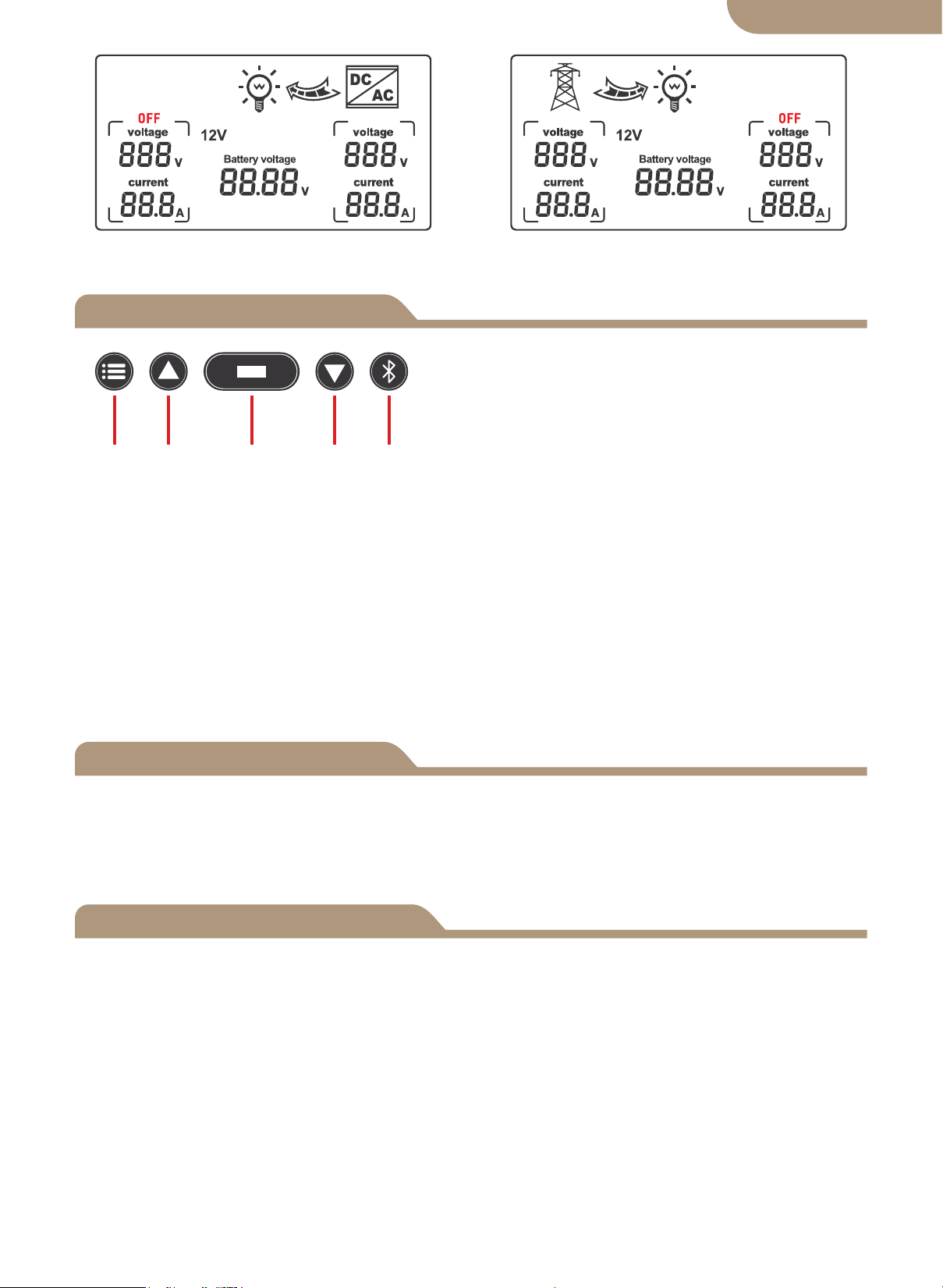
a. Battery level-LCD display.
b. Detection cut off and recovery point voltage
When it is detected that the battery voltage is lower than 10.5V for 2 seconds (system
default 11V), it is the low-voltage switching voltage, and the switching action is:
LCD- Right arrow flashes, LCD- Left arrow display turned off, battery
icon flashes.
When detecting the battery voltage rise 12.5V for 2 seconds (system default 13.5V), it
is the low-voltage recovery voltage, and the switching action is:
LCD- Right arrow display turned off, LCD- Left arrow shows flashing,
battery icon flashes off.
a. Battery level-LCD display.
b. Detection cut off and recovery point voltage
When it is detected that the battery voltage is lower than 21V for 2 seconds (system
default 22V), it is the low-voltage switching voltage, and the switching action is:
LCD- Right arrow flashes, LCD- Left arrow display turned off, battery
icon flashes.
When detecting the battery voltage rise 25V for 2 seconds(system default 27V), it is
the low-voltage recovery voltage, and the switching action is:
LCD- Right arrow display turned off, LCD- Left arrow shows flashing,
battery icon flashes off.
a. Battery level-LCD display.
b. Detection cut off and recovery point voltage
When it is detected that the battery voltage is lower than 42V for 2 seconds (system
default 44V), it is the low-voltage switching voltage, and the switching action is:
LCD- Right arrow flashes, LCD- Left arrow display turned off, battery
icon flashes.
When detecting the battery voltage rise 50V for 2 seconds(system default 54V), it is
the low-voltage recovery voltage, and the switching action is:
LCD- Right arrow display turned off, LCD- Left arrow shows flashing,
battery icon flashes off.
English version