MOGlabs CEL002 User manual

Cateye External Cavity Diode Laser
Model CEL002
Revision1.10

Limitation of Liability
MOGLaboratoriesPtyLtd(MOGLabs)doesnotassumeanyliabil-
ityarisingoutoftheuseoftheinformationcontainedwithinthis
manual. Thisdocumentmaycontainorreferenceinformationand
productsprotectedbycopyrightsorpatentsanddoesnotconvey
anylicenseunderthepatentrightsofMOGLabs,northerightsof
others. MOGLabswillnotbeliableforanydefectinhardwareor
softwareorlossorinadequacyofdataofanykind,orforanydirect,
indirect,incidental,orconsequentialdamagesinconnectionswith
orarisingoutoftheperformanceoruseofanyofitsproducts.The
foregoinglimitationofliabilityshallbeequallyapplicabletoany
serviceprovidedbyMOGLabs.
Copyright
Copyright c
MOGLaboratoriesPtyLtd(MOGLabs)2014–2017.
Nopartofthispublicationmaybereproduced,storedinaretrieval
system, or transmitted, in any form or by any means, electronic,
mechanical, photocopying or otherwise, without the prior written
permissionofMOGLabs.
Contact
Forfurtherinformation,pleasecontact:
MOGLaboratoriesP/L
49UniversitySt
CarltonVIC3053
AUSTRALIA
+61399390677
www.moglabs.com
MOGLabsUSALLC
41914thSt
HuntingdonPA16652
USA
+18142514363
www.moglabsusa.com
MOGLabsEurope
Goethepark9
10627Berlin
Germany
+493021960959

Preface
Diodelaserscanbewonderfulthings: theyareefficient,compact,
lowcost,highpower,lownoise,tunable,andcoveralargerangeof
wavelengths.Theycanalsobeobstreperous,sensitive,andtempera-
mental,particularlyexternalcavitydiodelasers(ECDLs).Withexter-
nalcavityfeedbackandadvancedelectronicssuchastheMOGLabs
DLC external cavity diode laser controller, a simple $10 100mW
AlGaAsdiodecanbecomearesearch-qualitynarrow-linewidthtun-
ablelaser.TheCEL“cateye”laserdescribedhereprovidesarobust,
stable, acousticallyinert, lowlinewidthandhighlytunable laser
alternative.
Wewouldliketothankthemanypeoplethathavecontributedtheir
hardwork,ideas,andinspiration,inparticularDanielThompson,
SebastianSalibaandMichaelVentura.
WehopethatyouenjoyusingtheMOGLabsCEL.Pleaseletusknow
ifyouhaveanysuggestionsforimprovementinthelaserorinthis
document,sothatwecanmakelifeinthelaserlabeasierforall,
andcheckourwebsitefromtimetotimeforupdatedinformation.
MOGLabs,Melbourne,Australia
www.moglabs.com
i

ii

Safety Precautions
Safeandeffectiveuseofthisproductisveryimportant.Pleaseread
thefollowinglasersafetyinformationbeforeattemptingtooperate
thelaser. Alsopleasenoteseveralspecificandunusualcaution-
arynotesbeforeusingMOGLabslasers,inadditiontothesafety
precautionsthatarestandardforanyelectronicequipmentorfor
laser-relatedinstrumentation.
CAUTION–USEOFCONTROLSORADJUSTMENTSOR
PERFORMANCEOFPROCEDURESOTHERTHANTHOSE
SPECIFIEDHEREINMAYRESULTINHAZARDOUS
RADIATIONEXPOSURE
LaseroutputfromtheCEL canbedangerous. Pleaseensurethat
youimplementtheappropriatehazardminimisationsforyourenvi-
ronment,suchaslasersafetygoggles,beamblocks,anddoorinter-
locks. MOGLabstakesnoresponsibilityforsafeconfigurationand
useofthelaser.Please:
•Avoiddirectexposuretothebeam.
•Avoidlookingdirectlyintothebeam.
•Notethesafetylabels(examplesshowninfigurebelow)and
heedtheirwarnings.
•Whenthelaserisswitchedon,therewillbeashortdelayof
twosecondsbeforetheemissionoflaserradiation,mandated
byEuropeanlasersafetyregulations(IEC60825-1).
•TheSTANDBY/RUN keyswitchmustbeturnedtoRUN before
thelasercanbeswitchedon. Thelaserwillnotoperateif
iii

iv thekeyswitchisintheSTANDBYposition.Thekeycannotbe
removedfromthecontrollerwhenitisintheclockwise(RUN)
position.
•Tocompletelyshutoffpowertotheunit,turnthekeyswitch
anti-clockwise (STANDBY position), switch the mains power
switchatrearofunittoOFF,andunplugtheunit.
•WhentheSTANDBY/RUNkeyswitchisonSTANDBY,therecan-
notbepowertothelaserdiode,butpowerisstillbeingsup-
pliedtothelaserheadfortemperaturecontrol.
WARNING Theinternalcircuitboardandpiezoelectrictransducersareat
highvoltageduringoperation.Theunitshouldnotbeoperated
withcoversremoved.
CAUTION AlthoughtheCEL isdesignedandpricedwiththeexpecta-
tionthattheend-usercanreplacethediodeandchangethe
alignment,somecomponentsarefragile.Inparticularthefilter,
piezoactuator,andoutputcouplerareveryeasilydamaged.
Pleasetakecareoftheseitemswhenworkinginsidethelaser.
The filter and output coupler are hard-coated and can be
cleanedbutgreatcareisneededaswithanyintracavitylaser
optics.
NOTE MOGLabsproductsaredesignedforuseinscientificresearch
laboratories.Theyshouldnotbeusedforconsumerormedical
applications.
Label identification
TheInternationalElectrotechnicalCommissionlasersafetystandard
IEC60825-1:2007mandateswarninglabelsthatprovideinformation
onthewavelengthandpowerofemittedlaserradiation,andwhich
showtheaperturewherelaserradiationisemitted.Figures1and2
showsexamplesoftheselabelsandtheirlocationontheCELlaser.

v
Model number:
CEL002
Serial number:
A30013011504-01
Manufactured:
APRIL 2015
Complieswith21 CFR 1040.10,and 1040.11 exceptfor
deviationspursuantto Laser NoticeNo.50,dated24June2007
MOG Laboratories Pty Ltd, 18 Boase St
Brunswick VIC 3056, AUSTRALIA
IEC 60825-1:2007
AS/NZS 2211.5:2006
INVISIBLE LASER RADIATION
AVOID EXPOSURE TO BEAM
CLASS 3B LASER PRODUCT
Wavelength
750 – 790 nm
Max Power
200 mW
Model number: CEL002
Serial number: A30013011504-01
Manufactured: APRIL 2015
Complieswith21CFR 1040.10,and1040.11 exceptfor
deviations pursuantto Laser NoticeNo.50,dated24June 2007
MOG Laboratories Pty Ltd, 18 Boase St
Brunswick VIC 3056, AUSTRALIA
IEC 60825-1:2007
AS/NZS 2211.5:2006
INVISIBLE LASER RADIATION
AVOID EXPOSURETO BEAM
CLASS 3B LASER PRODUCT
Wavelength
750 – 790 nm
Max Power
200 mW
Emission indicator
Figure 1: Schematic showing location of laser warning labels compli-
antwithInternationalElectrotechnicalCommissionstandardIEC60825-
1:2007,andUSFDAcompliancelabel. Aperturelabelengravedonthe
frontoftheCELlaserneartheexitaperture;warningadvisorylabelonthe
rearandcompliancelabelonside.

vi
AVOID EXPOSURE
LASER RADIATION IS
EMITTED FROM THIS APERTURE Aperture label engraving
Warning and advisory label
Class 3B
US FDA compliance
Model number: CEL002
Serial number: A30013011504-01
Manufactured: APRIL 2015
Complieswith21 CFR1040.10, and1040.11 exceptfor
deviations pursuantto Laser NoticeNo.50,dated24 June2007
MOG Laboratories Pty Ltd, 18 Boase St
Brunswick VIC 3056, AUSTRALIA
IEC 60825-1:2007
AS/NZS 2211.5:2006
INVISIBLE LASER RADIATION
AVOID EXPOSURE TO BEAM
CLASS 3B LASER PRODUCT
Wavelength
750 – 790 nm
Max Power
200 mW
Figure 2: WarningadvisoryandUSFDAcompliancelabels.

Protection Features
MOGLabslasersincludesanumberoffeaturestoprotectyouand
yourlaser.
Protection relay Whenthepowerisoff,orifthelaserisoff,thelaserdiode
isshortedviaanormally-closedsolid-staterelayatthelaser
headboard.
Emission indicator TheMOGLabscontrollerwillilluminatetheemissionwarn-
ingindicatorLEDimmediatelywhenthelaserisswitchedon.
Therewillthenbeadelayofatleast2secondsbeforeactual
laseremission.
Interlock Itisassumedthatthelaserpowersupplyiskeyedandinter-
lockedforsafety.Thelaserheadboardalsoprovidesconnec-
tionforaninterlock(seeappendixB),ifusedwithapower
supplywhichdoesnotincludesuchaninterlock.
vii

RoHS Certification of
Conformance
MOGLaboratoriesPtyLtdcertifiesthattheMOGLabsExternalCav-
ityDiodeLaserdoesnotfallunderthescopedefinedinRoHS Di-
rective 2002/95/EC,andisnotsubjecttocompliance,inaccordance
withDIRECTIVE 2002/95/EC Out of Scope; Electronics related;
Intended application is for Monitoring and Control or Medical In-
strumentation.
MOGLaboratoriesPty Ltdmakesnoclaimsorinferencesof the
compliancestatusofitsproductsifusedotherthanfortheirintended
purpose.
viii

Contents
Preface i
Safety iii
Protection Features vii
RoHS Certification of Conformance viii
1 Introduction 1
1.1 Externalcavity...................... 2
1.2 Modecompetition. . . . . . . . . . . . . . . . . . . . . 3
1.3 Piezo-electricfrequencycontrol . . . . . . . . . . . . 3
1.4 Temperatureandcurrent. . . . . . . . . . . . . . . . . 4
2 First light 5
2.1 Temperature........................ 6
2.2 Current........................... 7
3 Operation 9
3.1 Wavelength........................ 9
3.2 Scanning.......................... 11
3.3 Externalmodulation . . . . . . . . . . . . . . . . . . . 12
4 Alignment 13
4.1 Pre-alignmentoflenstubeanddiode . . . . . . . . . 13
4.2 Initialdiodetest . . . . . . . . . . . . . . . . . . . . . 15
4.3 Orientationandpolarisationoftheoutputbeam. . . 15
4.4 Cateyereflector...................... 16
A Specifications 19
A.1 RFresponse........................ 21
ix

xContents
A.2Mechanical........................ 22
B Laser head board 23
B.1 B1045/1046headboard . . . . . . . . . . . . . . . . . 24
B.2 B1047/B1240headboards. . . . . . . . . . . . . . . . 25
B.2.1 SMAinput..................... 26
B.3 Laserconnection . . . . . . . . . . . . . . . . . . . . . 27
B.4RFcoupling........................ 27
References 32

1. Introduction
Semiconductorlaserdiodesarecompact,efficientandlow-cost,but
usuallyhavepoorwavelengthcontrol,linewidthandstability. The
addition of an external frequency-selective cavity allows control
oftheoperatingwavelengthoverafewnmrange,withsub-MHz
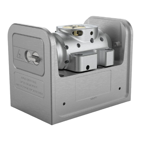
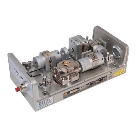
linewidthandstability.TheMOGLabsCEL(seeFig.1.1)ismachined
fromasolidaluminiumblock, sothatthelaseris stable, robust,
andinsensitivetoacousticdisturbances.Thecavityishermetically
sealedforadditionalsuppressionofenvironmentalfluctuationsand
drift.
TheMOGLabsCELisa“cat-eye”design(seeFig.1.2),inwhichan
externalcavityisformedbetweentherearreflectingsurfaceofthe
semiconductordiode,andacat-eyereflectoratseveralcentimetres
fromthediode[1–3]. Ratherthanthecustomarydiffractiongrating
ofLittrow-configurationECDLs,ahighefficiencyultranarrowfilter
Figure 1.1: InsidetheMOGLabsCELcateyelaser.
1

2Chapter 1. Introduction
isusedtoselectasingleexternalcavitymode. Withouttheneed
forilluminatingalargeareaofagratingforfeedback,acat-eye
retroreflectorandpartiallytransmittingoutputcouplercanbeused
toformtheexternalcavity. Thecateyereflectorisinherentlyself-
aligning, so thatthe laserisextremelyinsensitivetomechanical
disturbance,andalsoensureshighfeedbackcouplingefficiencyand
consequentlynarrowlinewidth.
DIODE FILTER LENS LENS
LENS PZT
OC
Figure 1.2: Schematicofacateyeexternalcavitydiodelaser(ECDL).The
externalcavity,formedbytherearfacetofthelaserdiodeandtheoutput
coupler,determinesthelaserfrequency. Onelongitudinalcavitymodeis
selectedbyanultranarrowintracavitybandpassfilter. Acateyereflector
isformedbytheoutputcoupler(OC)andintracavitylens,andthelightis
recollimatedbytheextracavityoutputlens.
Theoutputbeamfromalaserdiodeiscollimatedwithahighnumeri-
calaperture(NA)lensandincidentonthefilter.Thefiltertransmis-
sionwavelengthdependsontherotationangle.Transmittedlightis
back-reflectedbythecateyelens/output-couplercombinationwhich
efficientlycoupleslightbackintothelaserdiode.Moredetailscan
befoundinthereferences[1–3].
1.1 External cavity
Semiconductorlaserdiodesnormallyhaveahighreflectivityrear
facetandafrontfacetwithreflectivityofonlyafewpercent. The
diodecavityiscalledtheintrinsicorinternalcavity. Theexternal
cavityisformedbythecateyeandthedioderearfacet,andwhen
theexternalfeedbackisgreaterthanthatofthefrontfacet,theex-

1.2 Mode competition 3
ternalcavitydeterminesthelasingwavelength.Theexternalcavity
istypicallyaround40mmlongfromrearfacetofsemiconductorto
outputcoupler,givingacavitymodespacing(FSR)ofc/2L=3to
4GHz.
Thelaserdiodeandcollimatinglensareheldrigidlyinafocusing
tube. Thefilterisfixedtoabearing-mountedrotationassembly
withfineactuatorscrewstoadjusttheangle. Thespring-loaded
screws operate in a push-pull arrangement which can be locked
againsteachothertofurtherreducetheeffectsofmechanicalvibra-
tion.Variationofthefilterangleisusedforcoarseselectionofthe
wavelength,withinthegainbandwidthofthelaserdiode.
1.2 Mode competition
Asthewavelengthisvaried,competitionbetweenthefrequencyde-
terminedbytheinternalandexternalcavities,andthefiltertrans-
missionwindow,leadstomode hops.Fromfigure1.3itcanbeseen
thatthenetgain(combinedproductofsemiconductorgain, filter
loss,internalandexternalcavityinterference)canbeverysimilar
atadjacentexternalcavitymodes. Asmallchangeintheinternal
cavitymode,orthefilterangle,canleadtotheoverallgainbeing
greateratamodeadjacenttothemodeinwhichthelaserisos-
cillating,andthelaserthenhopstothathigher-gainmode. See
Ref.[4]foradetaileddiscussion.
1.3 Piezo-electric frequency control
Smallchangestothelaserfrequencyareachievedbycontrolling
theexternalcavitylengthwithapiezoelectricactuator. Forthe
MOGLabsCEL,theoutputcouplerismountedtoamultilayerpiezo-
electric“stack”.Thecavitylengthvariationisoforder10nmpervolt,
producingafrequencyshiftof70MHz/Vwitharangeof10GHzfor
150Vdrivevoltage. Thebandwidthislimitedbymechanicalreso-
nances,typically25kHz.

4Chapter 1. Introduction
384.0 384.1 384.2 384.3 384.4
Frequency (THz)
External cavity
Diode cavity
Diode gain
COMBINED
Filter
Figure 1.3: Schematicrepresentationforthevariousfrequency-dependent
factorsofanECDL,adaptedfromRef.[4],forwavelengthλ=780nmand
externalcavitylengthLext=15mm.
1.4 Temperature and current
Thelaserfrequencyisalsodependentontemperatureandinjection
current;thesensitivitiesaretypically3MHz/µAand30GHz/K[5].
Thus,low-noisestableelectronics,suchastheMOGLabsDLC ex-
ternalcavitydiode lasercontroller, areessential (seeRef.[6])to
achievesub-MHzlinewidthandstability.
AcriticalaspectofanECDListemperaturecontrolofthecavity,since
thelaserfrequencydependsonthecavitylengthandhenceonthe
thermalexpansioncoefficientofthecavitymaterial[4]. Thecavity
canbemachinedfrommaterialswithlowthermalexpansioncoeffi-
cientbuteventhenthepassivestabilityisinadequateforresearch
applications. Activefeedbackofthecavitytemperaturecombined
withcavitylengthcontrolprovideaflexibleandstableapproach.
TheMOGLabsCEL uses a negativetemperaturecoefficient(NTC)
thermistortosensethecavitytemperatureandPeltierthermoelec-
triccooler(TEC)toheatandcoolthecavitymaterial.

2. First light
Initialinstallationofthelaseristypicallyamatterofmountingit
toanopticaltableandconnectingtoaMOGLabscontroller. The
lasercanbemountedtopostsusingtheM3threadedholesonthe
base,orbyremovingthecoverandscrewingdirectlytotheoptical
tableusingtheM6x25socketheadcapscrewsprovided. Thehole
spacingalsoallowsdirectmountingtoimperialtablesfornon-metric
countries(Burma,LiberiaandtheUSA).
Thelaserincludesawatercoolingchannelforlaseroperationat
unusuallyhighorlowtemperatures,orinlaboratorieswithhighor
unstableairtemperature. Formostapplications,watercoolingis
notrequired;dissipationtotheairand/oropticaltableissufficient.
Theperformanceofanexternalcavitydiodelaserisstronglyde-
pendentontheexternalenvironment,andinparticularacousticvi-
brations. Verysmallchangesintheexternalcavitylengthhavea
largeeffectonthelaserfrequency,typically25MHzpernanometre
lengthchange. ThemonolithicblockconstructionoftheMOGLabs
CELreducestheinfluenceofvibrationsonthecavitylength,butsome
elasticityremains. Acousticdisturbancesintheairgapalsoaffect
thefrequency.Activefeedbacktothelaserfrequencyreducesthese
influences,butsomesimplemeasurestominimisecouplingtoenvi-
ronmentalvariationsandvibrationsourcesmaybewarranted. For
example,asurroundingboxtoreduceairmovementandaccidental
bumpingofthelaser;mountingthelasertoaheavysupport,andiso-
lationfromtheopticaltablewithanintermediarybreadboardwhich
isseparatedfromthemainopticaltablewithviscoelasticpolymer
(e.g.SorbothaneTM).
Oncethelaserismountedappropriately,thelasercanbeswitched
on. Pleaserefertothesuppliedtestdatafornominaltemperature
andcurrentsettings, andin particularbeawareof themaximum
currentlimit. 5

6Chapter 2. First light
ItisassumedthataMOGLabsDLCcontrollerwillbeusedtodrive
thelaser. Ifanalternativesupplyisused,notethat+5Vmustbe
providedonpin15oftheheadboardconnectortoopentheprotective
relay.SeesectionBforconnectiondetails.Alsopleaserefertothe
lasertestdataforthemaximumsafeoperatingcurrent.
2.1 Temperature
Thepreferreddiodetemperaturewilldependonthediode,there-
quiredwavelength,andtheambientroomtemperature. Forexam-
ple,typicalAlGaAsdiodesusedfordatastorageapplications(CD-R
burners)haveanominalwavelengthofλ=784nmat25◦C,with
adλ/dT slopeof−0.3nm/◦C,implyinganoptimumtemperatureof
about12◦. Dependingonthehumidity,lowtemperaturesmayin-
ducecondensationonthediodeandcollimationlens.Thefilterwill
determinethefinalwavelength,andthefeedbackisgenerallysuffi-
cientto“pull”thewavelengthby±5nm,andthusinthisexamplea
sensiblesettemperaturewouldbeabout17to18◦C.

2.2 Current 7
2.2 Current
Theoutputofsemiconductorlaserdiodesfollowanominallylinear
powervs. currentrelationship,oncethecurrentisaboveadevice-
specificthreshold(seeFig.2.1). Initiallythecurrentshouldbeset
above threshold, but well below the nominal maximum operating
current,untilthelaserisfullyaligned.
0
20
40
60
80
100
120
140
0 20 40 60 80 100 120 140 160180 200
Power (mW)
Injecon current(mA)
Bare 150mW diode
780.243nm
Extracavity
esmate
Figure 2.1: Samplelaserdiodepower-currentcharacteristiccurves,with
andwithoutanexternalcavity. Theoutputforadiodewithgoodanti-
reflectioncoatingisnegligible. Thestepsshowthatforhighercurrents,
someofthelightfromthediodeisnottransmittedbythefilter,typically
becausetheexternalcavitymodefrequencyisnotperfectlyalignedwith
thefiltertransmissionfrequency.

8Chapter 2. First light
Table of contents
Other MOGlabs Measuring Instrument manuals
Popular Measuring Instrument manuals by other brands

Keysight Technologies
Keysight Technologies E4990A Configuration guide

Dwyer Instruments
Dwyer Instruments 477A-1 Specifications - installation and operation instructions

Extech Instruments
Extech Instruments MA430T user manual

AGFA
AGFA CR 85-X Reference manual

Altera
Altera timequest quick start guide

BENDIX
BENDIX SmarTire BT36 quick start guide