MOGlabs CEL User manual

Cateye Laser
CEL, CEX and CEF
Revision2.01
SerialnumbersA323xxxxx

Limitation of Liability
MOGLaboratoriesPtyLtd(MOGLabs)doesnotassumeanyliabilityaris-
ingoutoftheuseoftheinformationcontainedwithinthismanual. This
documentmaycontainorreferenceinformationandproductsprotectedby
copyrightsorpatentsanddoesnotconveyanylicenseunderthepatent
rightsofMOGLabs,northerightsofothers. MOGLabswillnotbeliable
foranydefectinhardwareorsoftwareorlossorinadequacyofdataof
anykind,orforanydirect,indirect,incidental,orconsequentialdamages
inconnectionswithorarisingoutoftheperformanceoruseofanyofits
products. Theforegoinglimitationofliabilityshallbeequallyapplicable
toanyserviceprovidedbyMOGLabs.
Copyright
Copyright©MOGLaboratoriesPtyLtd(MOGLabs)2014–2023. No
partofthispublicationmaybereproduced,storedinaretrievalsystem,
ortransmitted,inanyformorbyanymeans,electronic,mechanical,pho-
tocopyingorotherwise,withoutthepriorwrittenpermissionofMOGLabs.
Contact
Forfurtherinformation,pleasecontact:
MOGLaboratoriesP/L
49UniversitySt
CarltonVIC3053
AUSTRALIA
+61399390677
MOGLabsUSALLC
41914thSt
HuntingdonPA16652
USA
+18142514363
www.moglabs.com

Preface
Diodelaserscanbewonderfulthings:theyareefficient,compact,lowcost,
highpower,lownoise,tunable,andcoveralargerangeofwavelengths.
Theycanalsobeobstreperous,sensitive,andtemperamental,particularly
externalcavitydiodelasers(ECDLs). Incombinationwithadvancedelec-
tronicssuchastheMOGLabsDLC externalcavitydiodelasercontroller,
the“cateye”laserdescribedhereprovidesarobust,stable,acoustically
inert,lowlinewidthandhighlytunablelasersystem.
WehopethattheMOGLabscateyelaserworkswellforyourapplication.
Pleaseletusknowifyouhaveanysuggestionsforimprovementinthe
laserorinthisdocument,sothatwecanmakelifeinthelaserlabeasier
forall,andcheckourwebsitefromtimetotimeforupdatedinformation.
MOGLabs,Melbourne,Australia
www.moglabs.com
i

ii

Safety Precautions
Safeandeffectiveuseofthisproductisveryimportant. Pleasereadthe
followinglasersafetyinformationbeforeattemptingtooperatethelaser.
Alsopleasenoteseveralspecificandunusualcautionarynotesbeforeusing
MOGLabslasers,inadditiontothesafetyprecautionsthatarestandard
foranyelectronicequipmentorforlaser-relatedinstrumentation.
CAUTION–USEOFCONTROLSORADJUSTMENTSOR
PERFORMANCEOFPROCEDURESOTHERTHANTHOSE
SPECIFIEDHEREINMAYRESULTINHAZARDOUSRADIATION
EXPOSURE
LaseroutputfromtheCEL/CEX/CEFcanbedangerous.Pleaseensurethat
youimplementtheappropriatehazardminimisationsforyourenvironment,
suchaslasersafetygoggles,beamblocks,anddoorinterlocks.MOGLabs
takesnoresponsibilityforsafeconfigurationanduseofthelaser.Please:
•Avoiddirectexposuretothebeam.
•Avoidlookingdirectlyintothebeam.
•Notethesafetylabels(examplesshowninfigurebelow)andheed
theirwarnings.
•Whenthelaserisswitchedon,therewillbeashortdelayoftwosec-
ondsbeforetheemissionoflaserradiation,mandatedbyEuropean
lasersafetyregulations(IEC60825-1).
•TheSTANDBY/RUNkeyswitchmustbeturnedtoRUNbeforethelaser
can be switched on. The laser will not operate if the keyswitch
isintheSTANDBY position. Thekeycannotberemovedfromthe
controllerwhenitisintheclockwise(RUN)position.
iii

iv •Tocompletelyshutoffpowertotheunit,turnthekeyswitchanti-
clockwise(STANDBYposition),switchthemainspowerswitchatrear
ofunittoOFF,andunplugtheunit.
•WhentheSTANDBY/RUNkeyswitchisonSTANDBY,therecannotbe
powertothelaserdiode,butpowerisstillbeingsuppliedtothe
laserheadfortemperaturecontrol.
WARNING Theinternalcircuitboardandpiezoelectrictransducersareathigh
voltage during operation. The unit should not be operated with
coversremoved.
CAUTION AlthoughtheCEL/CEX/CEFisdesignedandpricedwiththeexpecta-
tionthattheend-usercanreplacethediodeandchangethealign-
ment, somecomponentsarefragile. Inparticularthefilter, piezo
actuator,andoutputcouplerareveryeasilydamaged. Pleasetake
careoftheseitemswhenworkinginsidethelaser.
Thefilterandoutputcouplerarehard-coatedandcanbecleaned
butgreatcareisneededaswithanyintracavitylaseroptics.
NOTE MOGLabsproductsaredesignedforuseinscientificresearchlabora-
tories.Theyshouldnotbeusedforconsumerormedicalapplications.
Label identification
TheInternationalElectrotechnicalCommissionlasersafetystandardIEC
60825-1:2007mandateswarninglabelsthatprovideinformationonthe
wavelength and power of emitted laser radiation, and which show the
aperturewherelaserradiationisemitted. Figure1showsexamplesof
theselabels,andfigures2and3showtheirlocationontheCELlaserand
large-chassisCEX/CEFversion.

v
AVOID EXPOSURE
LASER RADIATION IS
EMITTED FROM THIS APERTURE Aperture label engraving
Warning and advisory label
Class 3B
US FDA compliance
Model number: CEL
Serial number: A32305001
Manufactured: MAY 2023
Complieswith21CFR1040.10,and1040.11 exceptfor
deviations pursuant to Laser NoticeNo.50,dated24June2007
MOG Laboratories Pty Ltd, 49 University St
Carlton VIC 3053, AUSTRALIA
IEC 60825-1:2007
AS/NZS 2211.5:2006
INVISIBLE LASER RADIATION
AVOID EXPOSURE TO BEAM
CLASS 3B LASER PRODUCT
Wavelength
750 – 790 nm
Max Power
200 mW
Figure 1: WarningadvisoryandUSFDAcompliancelabels.

vi
IEC 60825-1:2007
AS/NZS 2211.5:2006
INVISIBLE LASER RADIATION
AVOID EXPOSURETO BEAM
CLASS 3B LASER PRODUCT
Wavelength
750 – 790 nm
Max Power
200 mW
IEC 60825-1:2007
AS/NZS 2211.5:2006
INVISIBLE LASER RADIATION
AVOID EXPOSURE TO BEAM
CLASS 3B LASER PRODUCT
Wavelength
750 – 790 nm
Max Power
200 mW
Emission
indicator
Model number: CEL
Serial number: A32305001
Manufactured: MAY 2023
Complies with 21 CFR1040.10,and1040.11 exceptfor
deviationspursuant to Laser NoticeNo.50,dated 24June2007
MOG Laboratories Pty Ltd, 49 University St
Carlton VIC 3053, AUSTRALIA
Model number:
CEL
Serial number:
A32305001
Manufactured:
MAY 2023
Complieswith 21CFR1040.10,and1040.11 exceptfor
deviationspursuant to Laser NoticeNo.50, dated24 June2007
MOG Laboratories Pty Ltd, 49 University St
Carlton VIC 3053, AUSTRALIA
Figure 2: Schematicshowing location oflaserwarninglabels compliant with
InternationalElectrotechnicalCommissionstandardIEC60825-1:2007,andUS
FDAcompliancelabel. AperturelabelengravedonthefrontoftheCEL laser
neartheexitaperture;warningadvisorylabelontherearandcompliancelabel
onside.

vii
IEC 60825-1:2007
AS/NZS 2211.5:2006
INVISIBLE LASER RADIATION
AVOID EXPOSURE TO BEAM
CLASS 3B LASER PRODUCT
Wavelength
750 – 790 nm
Max Power
200 mW
Emission indicator
Model number: CEL
Serial number: A32305001
Manufactured: MAY 2023
Complieswith21CFR1040.10,and1040.11 except for
deviations pursuant to Laser NoticeNo.50,dated24June 2007
MOG Laboratories Pty Ltd, 49 University St
Carlton VIC 3053, AUSTRALIA
Figure 3: Schematic showing location of laser warning labels for the large-
chassisCEX/CEFversionofthecateyelaser(CEFoptionshown).

Protection Features
MOGLabslasersincludesanumberoffeaturestoprotectyouandyour
laser.
Protection relay Whenthepowerisoff,orifthelaserisoff,thelaserdiodeisshorted
viaanormally-closedsolid-staterelayatthelaserheadboard.
Emission indicator TheMOGLabscontrollerwillilluminatetheemissionwarningindi-
catorLED immediatelywhenthelaserisswitchedon. Therewill
thenbeadelayofatleast2secondsbeforeactuallaseremission.
Interlock Itisassumedthatthelaserpowersupplyiskeyedandinterlocked
forsafety. Thelaser head boardalsoprovidesconnectionfor an
interlock(seeappendixB),ifusedwithapowersupplywhichdoes
notincludesuchaninterlock.
viii

RoHS Certification of
Conformance
MOGLaboratoriesPtyLtdcertifiesthattheMOGLabsExternalCavity
Diode Laser does not fall under the scope defined in RoHS Directive
2002/95/EC,andisnotsubjecttocompliance,inaccordancewithDIREC-
TIVE 2002/95/EC Out of Scope; Electronics related; Intended application
is for Monitoring and Control or Medical Instrumentation.
MOGLaboratoriesPtyLtdmakesnoclaimsorinferencesofthecompliance
statusofitsproductsifusedotherthanfortheirintendedpurpose.
ix

Extending laser diode and
piezo lifetime
Atnight,switchtostandby:
1. Ifusingthelasertoseedanamplifier,firstturnofftheamplifier.
2. Switchthelaserdiodecurrentoff.
If using a MOGLabs DLC controller, don’t adjust the current, just
switchthetoggleup(off).
3. SwitchfromRUNtoSTANDBY.
ForaMOGLabsDLCcontrollerinstandbymode,thetemperaturecontroller
willcontinuetooperate,sothelaserisreadyforquickstartupthenext
day.Butthelaserdiodecurrentandpiezovoltagewillbezero,extending
theiroperatinglife.
Inthemorning,switchbackon:
1. SwitchfromSTANDBYtoRUN.
2. Switchthelaserdiodetoggledown(on).
Youdon’tneedtoadjustthecurrent,justwaitafewminutesforthe
diodetemperaturetoequilibrate.
YoushouldswitchyourMOGLabsDLCintoSTANDBY modeatnightsand
weekendsandwheneverthelaserisnotbeingusedformorethanafew
hours.Mostlasersneedtooperateonly40hoursduringa168hourweek;
thusswitchingtostandbymodecanextendthediodeandpiezolifetime
byafactoroffour. x

Contents
Preface i
Safety iii
Protection Features viii
RoHS Certification of Conformance ix
Extending laser diode & piezo lifetime x
1 Introduction 1
1.1 Externalcavity.......................... 2
1.1.1 Filter........................... 3
1.2 Piezo-electricfrequencycontrol . . . . . . . . . . . . . . . . 3
1.3 Temperatureandcurrent. . . . . . . . . . . . . . . . . . . . . 4
2 First light 5
2.1 Standby/Run........................... 5
2.2 Current............................... 5
2.3 Temperature............................ 6
3 Operation 9
3.1 Power............................... 9
3.2 Wavelength............................ 9
3.3 Mode-hops............................ 10
3.4 Scanning.............................. 12
3.5 Faradayisolator......................... 12
3.5.1 Faradayisolatoralignment. . . . . . . . . . . . . . . 13
4 Troubleshooting 17
4.1 Scanningadjustment . . . . . . . . . . . . . . . . . . . . . . . 17
xi

xii Contents
4.1.1 BIASoptimisation . . . . . . . . . . . . . . . . . . . . 18
4.2 Filteradjustment......................... 20
4.3 Thresholdoptimisation. . . . . . . . . . . . . . . . . . . . . . 21
4.4 Fibrecoupling........................... 24
4.4.1 Reversebeam: usingavisualfaultlocator. . . . . . 25
4.4.2 Mirroradjustment . . . . . . . . . . . . . . . . . . . . 25
A Specifications 29
A.1 CELmechanical(Rev9+) . . . . . . . . . . . . . . . . . . . . 31
A.2 CEX/CEFmechanical . . . . . . . . . . . . . . . . . . . . . . 32
B Laser head board 33
B.1 B1045/1046headboard . . . . . . . . . . . . . . . . . . . . . 34
B.1.1 RFcoupling....................... 34
B.2 B1047/B1240headboards. . . . . . . . . . . . . . . . . . . . 36
B.2.1 SMAinput......................... 37
B.3 Headboardconnectiontocontroller . . . . . . . . . . . . . . 38
References 41

1. Introduction
Semiconductorlaserdiodesarecompact,efficientandlow-cost,butusually
havepoorwavelengthcontrol,linewidthandstability. Theadditionofan
externalfrequency-selectivecavityallowscontroloftheoperatingwave-
lengthoverafewnmrange,withsub-MHzlinewidthandstability. The
MOGLabscateyelaser(seefigure1.1)ismachinedfromasolidaluminium
block,sothatthelaserisstable,robust,andinsensitivetoacousticdis-
turbances.Thecavityishermeticallysealedforadditionalsuppressionof
environmentalfluctuationsanddrift.Thecateyelaserblockismountedon
astandardchassis(CEL)oranextendedchassis(CEX)whichcanoptionally
includeafibreoutput(CEF).
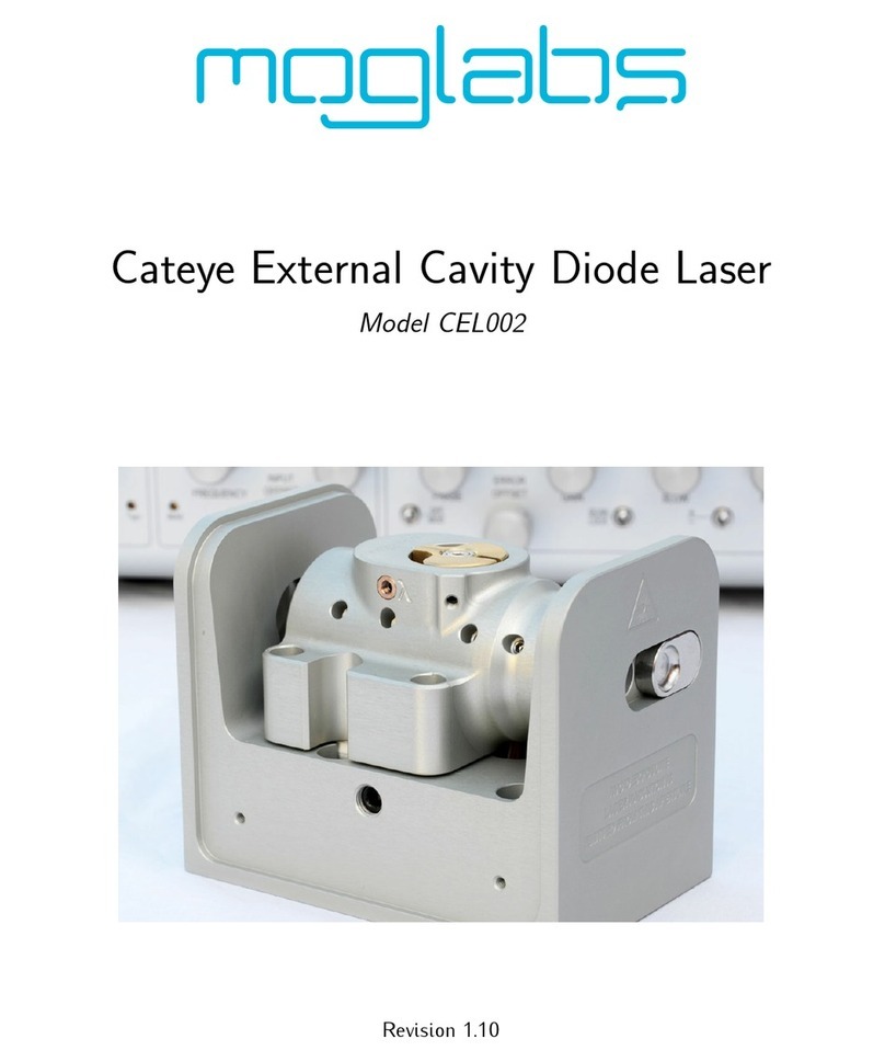
Figure 1.1: The MOGLabs CEL cateye laser. Mechanical version from 2023
shown(serialA323xxxxxandabove). 1

2Chapter 1. Introduction
TheMOGLabsCEL/CEX/CEFisa“cat-eye”design(seefigure1.2),inwhich
an external cavity is formed between the rear reflecting surface of the
semiconductordiode,andacat-eyereflectoratseveralcentimetresfrom
thediode[1–3]. RatherthanthecustomarydiffractiongratingofLittrow-
configurationECDLs,ahighefficiencyultranarrowfilterisusedtoselecta
singleexternalcavitymode.Withouttheneedforilluminatingalargearea
ofagratingforfeedback,acat-eyeretroreflectorandpartiallytransmitting
outputcoupler(OC)canbeusedtoformtheexternalcavity. Thecateye
reflectorisinherentlyself-aligning,sothatthelaserisextremelyinsen-
sitivetomechanicaldisturbance,andalsoensureshighfeedbackcoupling
efficiencyandconsequentlynarrowlinewidth.
DIODE FILTER L2 L3
L1 PZTOC
Figure 1.2: Schematicofacateyeexternalcavitydiodelaser(ECDL).Theex-
ternalcavity,formedbytherearfacetofthelaserdiodeandtheoutputcoupler
(OC),determinesthelaserfrequency. Onelongitudinalcavitymodeisselected
byanultranarrowintracavitybandpassfilter.Acateyereflectorisformedbythe
outputcouplerandintracavitylensL2.
Theoutputbeamfromalaserdiodeiscollimatedwithahighnumerical
aperture(NA)lensL1andthenincidentonthefilter. Thefiltertrans-
missionwavelengthdependsontherotationangle. Transmittedlightis
back-reflectedbythecateyelens/output-couplercombinationwhicheffi-
cientlycoupleslightbackintothelaserdiode. LensL2focuseslighton
theOCandlensL3re-collimatesthelaserbeam. Moredetailscanbe
foundinreferences[1–3].
1.1 External cavity
Semiconductorlaser diodesnormallyhave ahigh reflectivity rearfacet
andafrontfacetwithreflectivityofonlyafewpercent. Thediodecavity
iscalled the intrinsic or internal cavity. Theexternal cavity isformed

1.2 Piezo-electric frequency control 3
bytheOCandthedioderearfacet,andwhentheexternalfeedbackis
greater than that of the front facet, the external cavity determines the
lasingwavelength. Theeffectiveexternalcavityis20to40mmlongwith
cavitymodespacing(FSR)ofc/2nL =3.5to7GHz.
1.1.1 Filter
Thefilterselectsonelongitudinalcavitymode,androtationofthefilter
allowsselectionofwhichmode, withinthegainbandwidthofthelaser
diode(seefigure1.3).Filteradjustmentscanachievewavelengthchanges
betterthan0.1nmprecisionat780nm.
384.0 384.1 384.2 384.3 384.4
Frequency (THz)
External cavity
Diode cavity
Diode gain
COMBINED
Filter
Figure 1.3: Schematicrepresentationforthevariousfrequency-dependentfactors
ofanECDL,adaptedfromRef.[6],forwavelengthλ=780nmandexternalcavity
lengthLext=15mm.
1.2 Piezo-electric frequency control
Smallchangestothelaserfrequencyareachievedbycontrollingtheexter-
nalcavitylengthwithapiezoelectricactuator. FortheMOGLabscateye
laser,thefrequencychangeisabout20GHzoverthe150Vrangeofthe
piezo.

4Chapter 1. Introduction
1.3 Temperature and current
Thelaserfrequencyisalsodependentontemperatureandinjectioncur-
rent; thesensitivitiesare typically3MHz/µA and 30GHz/K [4]. Thus,
low-noisestable electronics, suchastheMOGLabs DLC externalcavity
diodelasercontroller,areessential[5]toachievesub-MHzlinewidthand
stability.
AnimportantaspectofanECDListemperaturecontrolofthecavity,since
thelaserfrequencydependsonthecavitylengthandhenceonthethermal
expansioncoefficientofthecavitymaterial[6].Thecavitycanbemachined
frommaterialswithlowthermalexpansioncoefficientbuteventhenthe
passivestabilityisinadequateforresearchapplications. Activefeedback
ofthecavitytemperatureandpiezocavitylengthprovideflexibleandstable
control.TheMOGLabscateyelaserusesanegativetemperaturecoefficient
(NTC)thermistortosensethecavitytemperatureandPeltierthermoelectric
cooler(TEC)toheatandcoolthecavitymaterial.

2. First light
Mount your laser to an optical table using the screws provided. Your
laserhasbeencarefullytunedtothespecificationsgiveninyourlaser
testreport. Pleasemakesureasyoucontinuewiththismanual,thatthe
diodeinjectioncurrent,temperatureandpiezooffset(FREQUENCY)match
thoseofthetestreport.
ItisassumedthataMOGLabsDLCcontrollerhasbeenprovidedwithyour
laser.Ifathirdpartycontrollerisused,pleasesetacurrentlimitaccording
tothemaximumsafeoperatingcurrentstipulatedinyourtestreport.
Forlongerwavelengthlasers, anIRupconversioncardorvideocamera
withoutIRfiltercanbeveryhelpful. Commonlow-costsecuritycameras,
computerUSB cameras,andhomemovieorstillcamerasarealsogood
options,althoughtheyoftenhaveIRfilterswhichmayneedtoberemoved.
2.1 Standby/Run
PleasefirstcheckthattheMOGLabsDLChasbeensettothecorrectmains
supplyvoltagebyinspectingtheredvoltageselectorabovetherearpanel
IEC powerinlet. Thenturn themain power switchon. Check thatthe
DLCinternalDIPswitchesmatchthelasertestreportspecification. Make
surethatthelaserdiodecurrentsupply(CURRENT knob)isturnedfully
anti-clockwise,andthattheOFF/MOD,SLOW andFAST lockswitchesare
off (up), and then turn the keyswitch from STANDBY to RUN. The LED
statusindicatorshouldbeyellowindicatingthatthethermistorandTEC
elementsareconnected.
2.2 Current
TurnthelaserdiodeCURRENTadjusttozero(fullyanti-clockwise). Note
thatfornormaldailyoperation,itisnotrecommendedtoturnthecurrent
tozero when turningoff the laser asthe soft-startfunctionof the DLC
5

6Chapter 2. First light
ensuresthatthecurrentisrampedupslowlyandsafelytotherequired
current. However,whenfirstaligningthelasertoyourexperiment,itis
importanttosetthelaseroutputpowertoalowvalueforsafety.
Adjustthediodecurrentto5–10mAandcheckthatthediodevoltage
(VOLTAGE selectionontheDLC8-way displayencoder)isthe sameas
listedinthediodedatasheet.Ifindoubt,pleasecontactMOGLabsbefore
continuing.
Thelaserthresholdcurrentisdefinedasthecurrentatwhichtheoutputis
1mW.AdjustCURRENTtoachieve1mWoutput,andifthethresholddiffers
fromthatinthetestreportbymorethan10mApleasereferto§4.3.
Abovethreshold,thelaserpowervs. injectioncurrentislinear(seefig-
ure 2.1). Initially the current should be set above threshold, but well
belowthemaximumoperatingcurrent,untilthelaserisfullyalignedwith
yourexperiment.
2.3 Temperature
TheoptimumtemperaturehasbeensetbyMOGLabsandshouldnotre-
quireadjustment. Oncethediodecurrentisset,allow5minutesforthe
temperaturetoreachequilibrium. Whenthelaserisnotneededforex-
tendedperiods, for exampleovernight, turn thelaser diodeoff andthe
keyswitchtoSTANDBY.In standbymode, the temperature controllerre-
mainsactive,sothatstableoperationcanbeachievedmorequicklythan
whentheDLCispoweredoff. ItisnotnecessarytochangetheCURRENT
settingwhenturningthelaserdiodeonandoff.
Other manuals for CEL
1
This manual suits for next models
2
Table of contents
Other MOGlabs Measuring Instrument manuals
Popular Measuring Instrument manuals by other brands

Hanna Instruments
Hanna Instruments HI 93703-11 instruction manual

FLUS
FLUS MT-903 user manual

SATAM
SATAM 7889 Series Description, Installation, Operations and Maintenance Manual

Brooks Instrument
Brooks Instrument Quantim QMBC2 quick start guide

Minolta
Minolta Auto Meter IV F instruction manual

General tools
General tools TQ-8800 Operation manual