www.polatrak.com
13813 FM 529 Rd, Houston, TX 77041 | US +1 (713) 983 7117 | Email: sales@stoprust.com
©2023 Deepwater Corrosion Services Inc.
7SMB-008 CP-Gun Manual Rev. 2
CP-GUN™ MANUAL
tails.aspx?prod=01903128&type=PROD
5.3.3 McMiller – Leak Stop Gel – Copper (II) sulphate electrolyte
MSDS http://documents.mcmiller.com/msds.html
Please contact your Polatrak representative for any questions and/or
issues regarding this manual.
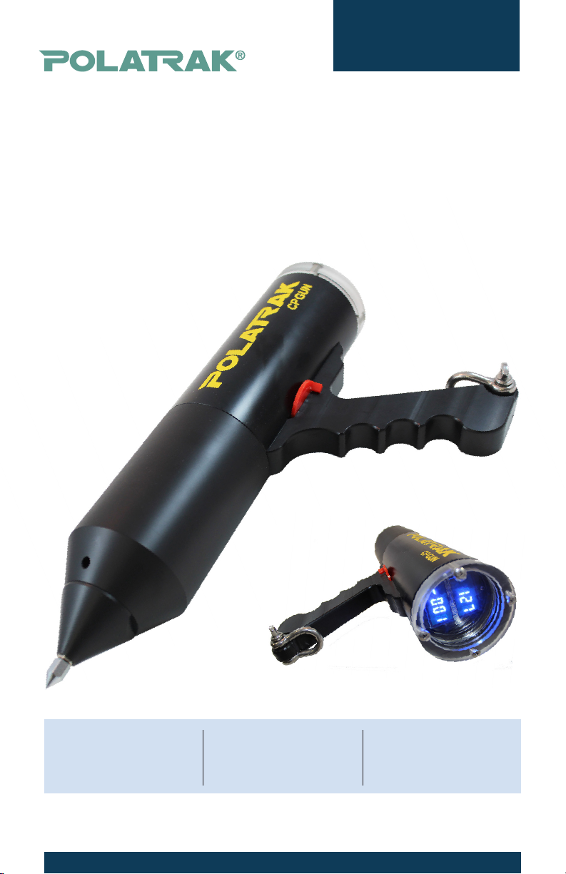
6. Components
The probe components are shown in Figure 2 along with a parts list in
Table 3. The CP Gun™ with handle weighs 6.3 lb (2.86 kg) in air and 1.5
lb (0.68 kg) in water. The following is a description of the major compo-
nents:
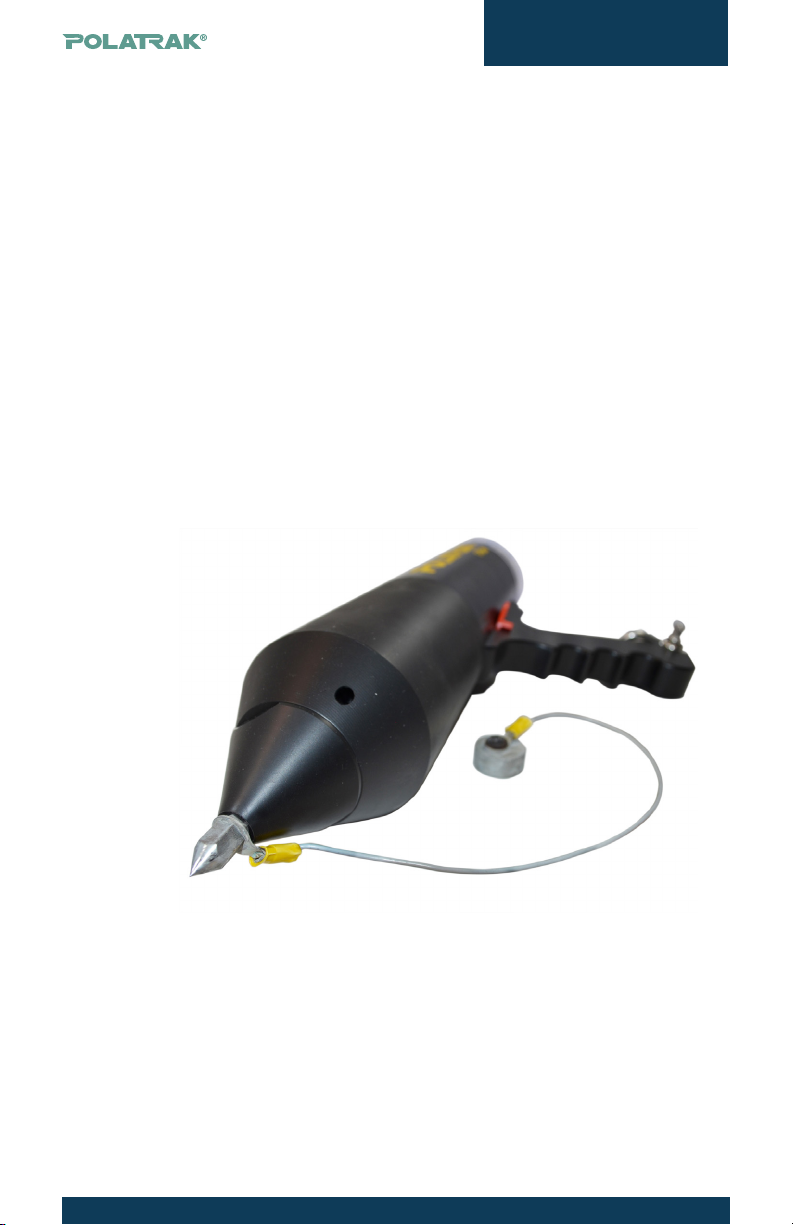
6.1 Main body
The rugged thermoplastic main body of the CP Gun™ comprises two
sections: a water-tight pressure housing which contains the LED
readout unit, batteries and electronic circuitry, and a free-ooding
element housing, which contains the reference electrodes, contact
tip and wiring harness. These two halves are separated by unscrew-
ing counterclockwise. This allows access to the probe contact tip
connection and the reference electrodes. The tip connector attaches
to the electrode harness, and once it’s unplugged, the entire elec-
trode housing can be removed. The electrode elements and contact
tip can be replaced as necessary. Please see Table 3 for part num-
bers and ordering information.
6.2 Reference electrodes
The CP Gun™ uses two replaceable silver/silver chloride (Ag/AgCl)
reference electrodes. Alternatively, copper/copper sulfate (Cu/
CuSO4) elements can be used for potential measurements taken in
fresh water. The electrodes are plugged into the electrode harness
via pressure-resistant connectors. To ensure proper function of the
reference cells, several points should be observed:
6.2.1 Any time the elements are replaced, a thin layer of connector
sealant should be applied to the rubber shoulder of the male end,
ensuring no sealant is applied to the copper pin. Please refer to the
MSDS before handling. All appropriate Personal Protective Equip-
ment (PPE) shall be worn, including safety glasses and disposable
gloves as a minimum.