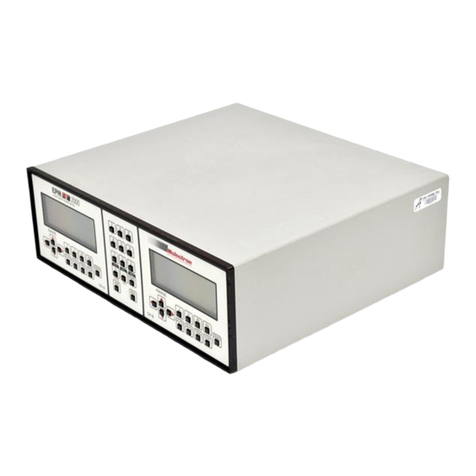
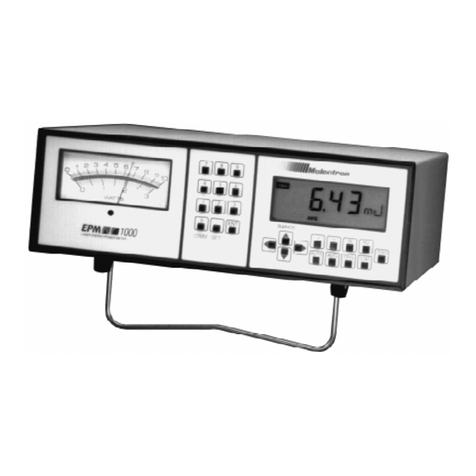
Molectron ENERGY MAX EM400 User manual

-~
ARTISAN
®
~I
TECHNOLOGY
GROUP
Your definitive source
for
quality
pre-owned
equipment.
Artisan Technology
Group
Full-service,
independent
repair
center
with
experienced
engineers
and
technicians
on staff.
We
buy
your
excess,
underutilized,
and
idle
equipment
along
with
credit
for
buybacks
and
trade-ins
.
Custom
engineering
so
your
equipment
works
exactly as
you
specify.
•
Critical
and
expedited
services
•
Leasing
/
Rentals/
Demos
• In
stock/
Ready-to-ship
•
!TAR-certified
secure
asset
solutions
Expert
team
ITrust
guarantee
I
100%
satisfaction
All
tr
ademarks,
br
a
nd
names, a
nd
br
a
nd
s a
pp
earing here
in
are
th
e property of
th
e
ir
r
es
pecti
ve
ow
ner
s.
Visit our website - Click HERE

USER MANUAL
EM400/EM500
Single-Channel Joulemeter


EM400/EM500 User Manual
August 2002
Published by
Molectron Detector, Incorporated
7470 SW Bridgeport Road
Portland, OR 97224
Phone: 800.366.4340 or 503.620.9069
Fax: 503.620.8964
www.molectron.com
© 2002 by Molectron Detector, Inc. All rights reserved.
No portion of this publication may be reproduced in whole or in part in
any form or by any means without permission of the publisher.
Document Number: 0980-0191

Features & Description ................................................................................................. 1
Overview ......................................................................................................................................................... 1
Controls ............................................................................................................................................................ 2
Arrow Keys ................................................................................................................................................. 2
AVG Key ..................................................................................................................................................... 2
J/V Key ....................................................................................................................................................... 2
On/Off Switch .............................................................................................................................................. 2
Stat Key ....................................................................................................................................................... 2
Indicators .......................................................................................................................................................... 3
Audible Tuning ............................................................................................................................................ 3
AVG Indicator .............................................................................................................................................. 3
Battery Indicator .......................................................................................................................................... 4
DEV Indicator ............................................................................................................................................... 4
LCD Numerical Display ............................................................................................................................. 4
MAX Indicator .............................................................................................................................................. 4
MIN Indicator ............................................................................................................................................... 4
TRG Indicator .............................................................................................................................................. 4
Other Connectors ............................................................................................................................................ 5
AC Wall Adapter Connector ...................................................................................................................... 5
Analog Out Connector ................................................................................................................................ 6
Input BNC Connector ................................................................................................................................. 6
RS-232 RJ11 Connector ........................................................................................................................... 7
Table of Contents

Safety & Maintenance ................................................................................................... 8
Cautionary Statements & Precautions .......................................................................................................... 8
User Maintenance ........................................................................................................................................... 9
Service & Calibration ....................................................................................................................................10
Operation ...................................................................................................................... 11
A Typical Energy Measurement ................................................................................................................. 11
AUTO-OFF Feature ...................................................................................................................................... 11
Normal Mode ................................................................................................................................................. 12
J/V Selection ............................................................................................................................................. 12
Range Selection ....................................................................................................................................... 12
Calibration Set Function .......................................................................................................................... 13
Avererage Mode ............................................................................................................................................ 14
Average Pulse Set Function ................................................................................................................... 14
Range Selection ....................................................................................................................................... 14
Statistics Mode .............................................................................................................................................. 15
Statistics Batch Set Function .................................................................................................................. 15
Statistics Functions .................................................................................................................................. 16
Remote Operation ........................................................................................................ 17
Serial Port Parameters .................................................................................................................................. 17
ADC Data Format .......................................................................................................................................... 18
Commands..................................................................................................................................................... 19
Query Firmware Version ........................................................................................................................ 19
Query Full Scale Reading ...................................................................................................................... 20

Query Measurement Mode ..................................................................................................................... 20
Query Range ............................................................................................................................................ 20
Query Responsivity ................................................................................................................................21
Restore Default Setup .............................................................................................................................. 21
Set Joules Measurement ......................................................................................................................... 22
Set Range .................................................................................................................................................. 22
Set Responsivity...................................................................................................................................... 22
Set Volts Measurement ............................................................................................................................ 22
Start Data Transmission .......................................................................................................................... 23
Stop Data Transmission .......................................................................................................................... 23
Compatible Detectors & Ranges ................................................................................ 24
Frequently Asked Questions ...................................................................................... 25
Specifications .............................................................................................................. 27
Instrument Specifications .............................................................................................................................. 27
Display....................................................................................................................................................... 27
Ranges ...................................................................................................................................................... 27
Maximum Input Pulse Amplitude ........................................................................................................... 27
Minimum Input Trigger Level .................................................................................................................. 27
Maximum Rep Rate ................................................................................................................................27
Linearity ..................................................................................................................................................... 27
Accuracy ................................................................................................................................................... 27
Input Impedance ....................................................................................................................................... 27
Trigger Level ............................................................................................................................................. 27
Table of Contents
(cont’d)

Averaging .................................................................................................................................................. 27
Calibration Factors ................................................................................................................................... 28
EM500 Analog Output .............................................................................................................................. 28
Output Impedance ....................................................................................................................................28
Data Conversion Digital Resolution ....................................................................................................... 28
EM500 RS-232 Interface ......................................................................................................................... 28
EM500 RS-232 Baud Rate ...................................................................................................................... 28
EM500 RS-232 Parity .............................................................................................................................. 28
EM500 RS-232 Data Bits ......................................................................................................................... 28
EM500 RS-232 Stop Bits ......................................................................................................................... 28
Battery Life, EM400 .................................................................................................................................28
Battery Life, EM500 .................................................................................................................................28
EM500 Battery Recharge Time ............................................................................................................. 29
Battery AUTO-OFF timeout .................................................................................................................... 29
Dimensions................................................................................................................................................ 29
Weight, EM400 .......................................................................................................................................... 29
Weight, EM500 .......................................................................................................................................... 29
Factory Default Settings ............................................................................................................................... 29
Warranted Characteristics ............................................................................................................................ 30
Power......................................................................................................................................................... 30
Atmospherics ............................................................................................................................................ 30
Dynamics .................................................................................................................................................. 30
Emissions.................................................................................................................................................. 30
Susceptibility ............................................................................................................................................. 31

1
Features & Description
Overview
Thank you for purchasing a Molectron EM400/EM500. These devices are portable, battery-operated, single-channel
laser joulemeters for production line testing and field service applications. Microprocessor-based instruments, they are
designed to operate with Molectron's J25 and J50 series pyroelectric probes. The EM500 has an added computer interface
capability.
The EM400/EM500 is fast, accurate, and easy to use. It features a large 4-digit numeric display and an AUTO-OFF
feature to conserve battery life. It supports a wide range of user-selected calibration factors and a wide dynamic range of
inputs. It displays directly in energy units. The EM500 features a 3-wire RS232 interface, an analog output, an audible
tuning function, and an internal rechargeable battery. Both units include an AC adapter, which also charges the internal
battery of the EM500.
The EM400/EM500 has three operating modes:
• Normal mode displays the instantaneous energy of the laser on a pulse-to-pulse basis.
• Average mode calculates and displays a user-selected 2-99 pulse average.
• Statistics mode accumulates 2 to 9999 pulses and provides four kinds of numeric results (Average,
Minimum, Maximum, and Standard Deviation) for the accumulated set.

2
Controls
Press the key to select a higher range in Normal or Average mode or to increase the value in Set functions.
Press the key to select a lower range in Normal or Average mode or to decrease the value in Set functions.
Press and/or to select digits in Set functions, to select a computation function (Average, Minimum,
Maximum, or Standard Deviation) in Statistics mode, or to operate the Audible Tuning Function.
Press to enter Average mode and to perform averaging operations.
Press to enter Normal mode and its functions, and to switch the reading between Joules and Volts.
Slide to the right to power up the EM400/EM500.
Press to enter Statistics mode and to perform statistical operations.
Arrow Keys
AVG Key
J/V Key
On/Off Switch
STAT Key

3
Indicators
The Audible Tuning function can be entered from either Normal or Average mode. When enabled, the audible tone sets
to 50% of its maximum frequency. When the initial reading (the reading at the moment the audible tone is enabled) is
increased by 100%, the audible tone increases to 100%. Likewise, a 100% decrease lowers the frequency to zero. When
the audible tone reaches 100% or more (the display has increased 100% or more), the tone will beep on and off.
Press the and keys simultaneously to activate the Audible Tuning function.
Press the and keys simultaneously when the audible tone output is 100% or more to reset at 50% frequency.
Press the and keys simultaneously when the audible tone output is less than 100% to disable the Audible
Tuning function. Reminder: if the audible tone output is at 100% or more, pressing the and keys will restart
the function. If it is at less than 100%, pressing the same keys will disable the function.
Note: The EM500 Analog Output value is not valid while the instrument is in Audible Tuning mode (the output
value will still not exceed the specified 2.00V threshold).
The indicator flashes during Average mode. It’s activated steadily when the mean is being displayed in
Statisticsmode.
Audible Tuning
AVG Indicator

4
Battery Indicator
DEV Indicator
LCD Numerical Display
The EM400 and the EM500 indicate when the battery is low. When lit, replace the 9V battery in the
EM400 or recharge the internal battery in the EM500 with the supplied AC wall adapter. Note: Accurate readings
cannot be made when the Battery Indicator is lit.
switches on when Standard Deviation is being displayed in Statistics mode.
Four-digit numeric field
· Displays the instrument reading in Joules or Volts in all modes.
· Displays the constant value in Set functions.
Two-character alphanumeric field
· Displays the units of measure.
· Displays auxiliary information in Set functions.
indicates the statistical Maximum is being displayed in Statistics mode.
indicates the statistical Minimum is being displayed in Statistics mode.
indicates a valid trigger during live measurement. Flashes once for each trigger at repetition rates below
3 pps. Activated steadily at repetition rates above 3 pps.
MAX Indicator
MIN Indicator
TRG Indicator

5
Located on the left side of the instrument, it connects to the wall adapter (supplied), allowing the unit to be powered from
AC line power and the internal battery of the EM500 to be recharged. A replacement adapter, if needed, should be rated
18 V DC (±1 V DC), 500 mA. The output connector should be 5.1 mm (.20") O.D. and 2.55 mm (0.100") I.D.
Under normal conditions, the EM400's
battery will last 4 hours and the EM500's
internal NI-Cad battery will last 6 hours
with a recharge time of 14 hours.
Other Connectors
AC Wall Adapter Connector

6
To access the Analog Out connector, press down on the
compartment cover on the back of the EM500. Slide it
outward, away from the center of the instrument. Connects
to a voltmeter or a data acquisition system. It provides a DC
voltage proportional to the display reading. The output is
scaled for 2 Volts full scale for the range selected.
The Analog Output BNC's maximum output is 2.00 Volts.
Even though the EM500 LCD may exceed its selected full
scale under some conditions, the Analog Output value will never exceed 2.00 Volts.
Example: The LCD reads 3.47 mJ on the 20 mJ range (about 17 percent of full scale). The analog output will read
0.347 VDC.
Located on the right side of the instrument, the Input BNC
connects to a Molectron J25 or J50 series pyroelectric
probe.
Analog Out Connector
Input BNC Connector

7
RS-232 RJ11 Connector To access the RS232 connector, press down on the compartment cover on the back of the EM500. Slide it outward,
away from the center of the instrument. The RJ11 connector provides a 3-wire interface with an IBM compatible
computer through a standard 25-pin or 9-pin D sub connector. In the connector supplied with the EM500, the
RTS/CTS and DTR/DSR jumpers loop the PC's handshaking lines back to the PC to allow 3-wire data transmission;
these jumpers may not be required for all PC-based applications.

8
Safety & Maintenance
Cautionary Statements &
Precautions
These terms may appear on the product:
Warning indicates a personal injury hazard.
Caution indicates a hazard to property including the product.
Review the following safety precautions carefully to avoid injury or prevent damage to the instrument or other
equipment through misuse.
• Do not operate with suspected failures. If you suspect that this product is damaged, have it inspected
by qualified Molectron service personnel.
• Do not operate this product from a power source that applies more than the voltage specified.
• Do not apply a voltage outside the range specified to any terminal.
• Do not operate this product if its panels are removed.
• Do not operate this product in wet or damp conditions or in an explosive atmosphere.
• To prevent the product from overheating, provide proper ventilation.
The only user-serviceable parts of the EM400/EM500 are the batteries.

9
User Maintenance When the instrument activates , the EM400 battery must be replaced or the EM500 battery must be recharged.
Energy readings are not accurate while the instrument displays .
Replace the EM400's battery by pressing down on the battery compartment cover located on the back of the instrument.
Slide it outward, away from the center of the instrument.
The EM500 rechargable battery is not user-serviceable. Recharge it using the included AC Adapter.
There are no user-serviceable parts to an EM400 except the replaceable battery and there are no user-serviceable parts
of the EM500 at all.

10
Service & Calibration To maintain optimum NIST traceable performance, return the instrument to Molectron for annual recalibration.
In addition to recalibration, Molectron takes advantage of this annual service to upgrade firmware if necessary and
verify the unit functions within Molectron's strict performance standards.
Always contact Molectron before returning an instrument for calibration. To prepare an instrument to Molectron:
1. Contact Molectron Detector's Customer Service Department at (800) 366-4340 for a Return Material
Authorization number. Note: Material will not be accepted without a pre-assigned RMA number.
2. Attach a tag to the instrument, indicating the owner's name and address, contact person (if different
than owner), instrument serial number and assigned RMA number.
3. Pack the instrument in the original packaging. If original packaging is not available, wrap the
instrument with polyethylene sheeting (or equivalent) and pack it in a corrugated cardboard carton
with at least 7.5 cm (3") on all sides. Use a carton with at least 170 kg (375 lb) test strength.
4. Seal the carton tightly with shipping tape. Print TO and FROM addresses and RMA number clearly
on the outside of the carton.

11
Operation
A Typical Energy
Measurement
Measuring energy using and EM400/EM500 and a Molectron Pyroelectric Detector is easy. For a complete list
of compatible Detectors, see Compatible Probes & Ranges.
CAUTION: Do not exceed the power/energy density for the probe. Consult the detector data sheet, or test the
setup with a damage test slide as appropriate.
1. With the laser beam blocked or the laser turned OFF and the EM400/EM500 turned OFF, place the
pyroelectric probe in the path of the laser beam.
2. Connect the probe to the EM400/EM500 Input Connector using the BNC cable supplied with the
probe.
3. Switch ON the EM400/EM500.
4. Press to place the instrument in Normal mode. Press until the desired units (J/mJ/µJ or
V/mV/µV) are shown.
5. Unblock the laser beam or start the laser. Verify proper beam alignment on the center of the probe
surface.
6. Adjust the range by pressing or until is activated and a reading in Joules or Volts
appears on the LCD. If the LCD indicates OL, press the button until a valid reading occurs.
The EM400/EM500 has an AUTO-OFF feature to conserve battery life. Whenever there is five minutes of front panel
inactivity, the instrument shows a series of dashes (----) on the LCD display and automatically goes into AUTO-OFF. To
resume operation from an AUTO-OFF state, complete a power cycle by moving the On/Off switch to the OFF position
and then back to the ON position.
AUTO-OFF Feature

12
Normal mode displays the instantaneous energy of the laser on a pulse-to-pulse basis.
Press to enter Normal mode.
The EM400/EM500 can display Joules (J), millijoules (mJ), or microjoules (µJ); or Volts (V), millivolts (mV), or
microvolts (µV).
From Normal mode, press to shift between Joules and Volts.
During operations in Normal mode, press to select a higher range or
to select a lower range.
Normal Mode
J/V Selection
Range Selection
This manual suits for next models
1
Table of contents
Other Molectron Measuring Instrument manuals