Molectron EPM1000 User manual

-~
ARTISAN
®
~I
TECHNOLOGY
GROUP
Your definitive source
for
quality
pre-owned
equipment.
Artisan Technology
Group
Full-service,
independent
repair
center
with
experienced
engineers
and
technicians
on staff.
We
buy
your
excess,
underutilized,
and
idle
equipment
along
with
credit
for
buybacks
and
trade-ins
.
Custom
engineering
so
your
equipment
works
exactly as
you
specify.
•
Critical
and
expedited
services
•
Leasing
/
Rentals/
Demos
• In
stock/
Ready-to-ship
•
!TAR-certified
secure
asset
solutions
Expert
team
ITrust
guarantee
I
100%
satisfaction
All
tr
ademarks,
br
a
nd
names, a
nd
br
a
nd
s a
pp
earing here
in
are
th
e property of
th
e
ir
r
es
pecti
ve
ow
ner
s.
Find the Coherent / Molectron EPM1000 at our website: Click HERE

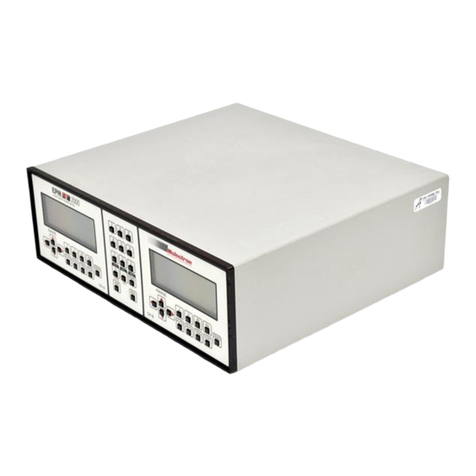
EPM1000
JOULEMETER/POWERMETER
USER’SGUIDE
USER’S GUIDE
Artisan Technology Group - Quality Instrumentation ... Guaranteed | (888) 88-SOURCE | www.artisantg.com

Artisan Technology Group - Quality Instrumentation ... Guaranteed | (888) 88-SOURCE | www.artisantg.com

EPM1000
SINGLE CHANNEL
JOULEMETER/POWER METER
USER’S GUIDE
Artisan Technology Group - Quality Instrumentation ... Guaranteed | (888) 88-SOURCE | www.artisantg.com

EPM1000 User’s Manual.
Revised September 21, 1998
Published by
Molectron Detector, Incorporated
7470 S.W. Bridgeport Road
Portland, OR 97224
(800) 366-4340 (503) 620-9069 FAX: (503) 620-8964
http://www.molectron.com
Copyright © 1998 by Molectron Detector, Inc.
All rights reserved. No portion of this book may be reproduced or transmitted in
whole or in part in any form or by any means without permission of the publisher.
Document Number: QI-4.6
Artisan Technology Group - Quality Instrumentation ... Guaranteed | (888) 88-SOURCE | www.artisantg.com

Table of Contents
EPM1000 User’s Guide
Table of Contents
Features & Description
Welcome 5
Overview 5
Unpacking and Inspecting the Instrument 5
Safety Information 6
Manual Information 7
Features 7
Interface 7
Units and Ranges 7
Compatible Probes 8
Understanding the EPM1000 Internal Trigger 8
Understanding the EPM1000 External Trigger 10
Understanding the EPM1000 Speedup Feature 11
Description 12
Rear Panel 12
Front Panel 14
Operation
Tutorial 19
Thermopile 19
Pyroelectric 20
Modes 21
Normal Mode 21
Auto Mode 21
Average Mode 21
Statistics Mode 22
Settings 22
System Settings 22
Trigger Settings 26
Communications Settings 27
Programming
Connection Methods 29
Commands 29
Audible Beeper 30
Average Batch Size 30
Backlight 30
Channel Store/Recall 30
Communications Error 31
Display Current Reading 31
Identification 31
IEEE-488 Address 31
Line Frequency 32
Artisan Technology Group - Quality Instrumentation ... Guaranteed | (888) 88-SOURCE | www.artisantg.com

Table of Contents
EPM1000 User’s Guide
Operating Mode 32
Output Buffer 32
Output Continuous 32
Output Depth 33
Output Dump 33
Output Format 33
Probe Type 36
Range, Current 36
Range, Maximum/Minimum 37
Reset 37
Responsivity 37
RS-232 Baud Rate 37
RS-232 Parity 38
RS-232 Stop Bits 38
Self Test 38
Speedup 38
Statistics Batch Size 39
Statistics Restart Mode 39
Statistics Send 39
Statistics Start 40
Trigger Level 40
Trigger Source 40
Units 40
Zero 41
Programming Example 42
Maintenance, Service, & Calibration
Troubleshooting 43
Fuse Replacement 45
Instrument Calibration and Service 45
Specifications
Electrical/Mechanical 47
Display 47
Ranges 47
Resolution 47
Maximum Rep Rate 47
Linearity 47
A/D Digital Resolution 47
Input Impendance 47
Noise Equivalent Voltage (NEV) 47
Analog Output 47
External Trigger Input 47
Artisan Technology Group - Quality Instrumentation ... Guaranteed | (888) 88-SOURCE | www.artisantg.com

Table of Contents
EPM1000 User’s Guide
Electronic Accuracy 48
System Accuracy 48
Maximum Pyroelectric Pulse Width 48
Internal Trigger 48
RS-232 Baud Rates 48
Power Requirements 48
Dimensions 48
Weight 48
Firmware Revisions 48
Factory Defaults 49
Warranted Characteristics 49
Power 49
Atmospherics (Temperature) 49
Atmospherics (Relative Humidity) 49
Atmospherics (Altitude) 49
Dynamics (Random Vibration) 49
Emissions 50
Susceptibility 50
Index 51
Artisan Technology Group - Quality Instrumentation ... Guaranteed | (888) 88-SOURCE | www.artisantg.com

Table of Contents
EPM1000 User’s Guide
Artisan Technology Group - Quality Instrumentation ... Guaranteed | (888) 88-SOURCE | www.artisantg.com

Features & Description
EPM1000 User’s Guide 5
Features & Description
Welcome
Overview Thank you for purchasing an EPM1000. The EPM1000 is a laboratory, AC
powered meter that can measure both pulsed and CW lasers: energy, power,
voltage, and (pulsed only) frequency. The EPM1000 is compatible with all
of Molectron Detector, Inc.’s pyroelectric, silicon, and PowerMax®thermo-
pile probes.
The EPM1000 is fast, accurate, and easy to use. It features:
• a large, custom four-digit LCD
• a 3½” mirrored analog meter
• four operating modes
• many functions
• peak reading with automatic baseline drift compensation
• results displayed in selected units
• an analog output
• an adjustable internal trigger
• an external trigger input
• an RS-232 communication port
• an IEEE-488 communication port
All instrument features are available via the communication ports.
Unpacking and
Inspecting the
Instrument
The equipment described in this manual was delivered to the carrier in
good condition and properly packaged. Immediately open all boxes
comprising this shipment and inspect the instruments for lost or damaged
parts, including case damage, proper button function, etc.
In the unlikely event of damage:
1. Save all shipping boxes and cartons for inspection by the
carrier until the claim is settled.
2. Notify the carrier or transfer agent immediately for a prompt
inspection of the claimed loss or damage.
3. File the claim with the carrier.
4. If necessary, order replacement parts from Molectron Detec-
tor, Inc. and collect the invoice amount from the carrier.
Artisan Technology Group - Quality Instrumentation ... Guaranteed | (888) 88-SOURCE | www.artisantg.com

Features & Description
EPM1000 User’s Guide
6
Safety Information
!Caution
!Warning
Review this safety information carefully to avoid injury and prevent
damage to this instrument or any instrument connected to it. There are
no user serviceable parts in the EPM1000. For Service, please see
Maintenance, Service, and Calibration.
This manual uses two terms to describe hazardous conditions: Caution
and Warning.
Warning indicates serious injury or death may occur.
Caution indicates possible damage to equipment.
Warnings:
• Use only the power cord specified for the EPM1000.
The grounding conductor of the cord must be con-
nected to earth ground.
• Do not operate the EPM1000 if its panels are removed
or any of the interior circuitry is exposed.
• Do not operate the EPM1000 in wet or damp condi-
tions or in an explosive atmosphere.
Cautions:
• Do not operate the EPM1000 from a power source
which applies more than the voltage specified.
• Do not apply a voltage outside the specified range to
any of the terminals.
• Use only the fuse type and rating specified for the
EPM1000.
• Provide proper ventilation to the EPM1000, particu-
larly near the ventilation slots in the back.
• Do not operate the EPM1000 with suspected failures.
Refer damaged units to qualified Molectron service
personnel.
• Never connect or disconnect a powered probe while
the EPM1000 is on. Damage could result to the probe,
the EPM1000 or both.
Artisan Technology Group - Quality Instrumentation ... Guaranteed | (888) 88-SOURCE | www.artisantg.com

Features & Description
EPM1000 User’s Guide 7
Manual Information This manual can be read sequentially, but should be stored near the
EPM1000 and used as a reference.
There are five basic components of this manual:
•Features & Description An introduction to the
EPM1000 and its features and controls
•Operation A tutorial and complete description of
the EPM1000’s functions
•Programming A list of commands and examples of
communicating with the EPM1000 via remote
•Maintenance, Service, and Calibration A list of
frequently asked questions, and information
regarding calibration and service
•Specifications The standards and limits of the
EPM1000
This manual was composed using Microsoft®Word and Adobe®
PageMaker®.
Features Interface The EPM1000 features a standard RS-232 9-pin connector on the back
panel. This can connect to any similar RS-232 port of a host PC.
IEEE-488 (or GPIB) interface is standard on every EPM1000. Use this
port for the following advantages:
• Transfer rates up to one Mbyte/sec
• Can be added to an already existing instrument chain
• Can be used with other EPM1000’s on the same host
computer
Units and Ranges The EPM1000 can measure:
•Energy 1 pJ to 10 J in 28 ranges (depending on the probe type)
•Power 1 mW to 10 kW in 15 ranges
•Frequency 0.1 Hz to 500 Hz
•Volts 2 mV to 30 V (for pyroelectric/silicon probes)
•Volts 200 µV to 1 V (for thermopile probes)
For more details, see Specifications.
Artisan Technology Group - Quality Instrumentation ... Guaranteed | (888) 88-SOURCE | www.artisantg.com

Features & Description
EPM1000 User’s Guide
8
Compatible Probes The EPM1000 functions with any of Molectron's pyroelectric/Joulemeter
probes with names of the form Jx (for example: J25, J3, J4).
All PowerMax®thermopile probes will function with the EPM1000.
Connect thermopile probes that terminate with a BNC connector to the
EPM1000 with the PM-BNC adapter (available separately).
Understanding the
EPM1000 Internal
Trigger
For greatest accuracy and repeatability, the EPM1000 must trigger
reliably for each laser pulse.
The EPM1000 should be triggered externally, via the Trigger In connec-
tor, for best results. This is particularly true in a noisy environment. The
EPM1000 can be set to synchronize with either the positive or negative
transition of this external signal.
Without a reliable external trigger, set the EPM1000 to extract an artifi-
cial trigger from the incoming signal. This is called Internal Triggering.
To successfully extract an internally generated trigger, set the EPM1000
to a range such that the incoming signal is at least 5% of the full scale.
Set the trigger level for at least 2% above the noise level and at least 2%
below the peak height.
For example, with a peak height of 300 mJ, set the EPM1000 to a range
of 3 J. A peak will occur at 10% of full scale, well above the 5% level.
The trigger level should not be set higher than 8%. If the noise level is
5% of full scale (approximately 150 mJ) then the trigger level should be
set no lower than 7%.
In Figure 1, the EPM1000's internal trigger threshold has been set to 8%
(dashed line). Pulse A will definitely not generate a reliable trigger.
Pulse B may generate a trigger, but not reliably. Pulses C and D will
definitely generate reliable triggers.
5%
10%
15%
Trigger
Level
ADCB
Definitely will not trigger
M
ay trigger, but not reliable
Definitely will trigger
Figure 1: Pulses which will or will not trigger as valid
Artisan Technology Group - Quality Instrumentation ... Guaranteed | (888) 88-SOURCE | www.artisantg.com
Features & Description
EPM1000 User’s Guide 9
Understanding the
EPM1000 Internal
Trigger
(continued)
The ranges differ by powers of ten. A full-scale signal on one range may
not trigger on the next higher range unless the trigger level is set to less
than 10%. For example, a near full-scale signal of 280 mJ on the 300 mJ
range is less than 10% of full scale on the next higher range (2 J) and
would not trigger the reading, so adjust the trigger level to less than 8%
for reliable triggering.
The trigger is synchronous with the leading edge of the pulse, but the
actual peak is determined algorithmically by sampling the input signal
near the trigger. From the trigger point forward, the algorithm searches
for peaks and from the trigger point back, it searches for a baseline.
The EPM1000 can be programmed to ignore triggers for a specified time
after a valid trigger. This prevents “false” triggers in pulse tails from
accidentally starting a new sample (see Figure 2). This amount of delay
time is called the Trigger Holdoff (see Operation -- Operation Settings --
Trigger Settings -- Trigger Holdoff). The EPM1000 is set at the factory
with a 1 ms trigger holdoff.
5%
10%
15%
Trigger
Level
Possible
False
Trigger
1 ms 2 ms
Figure 2: How a false trigger could occur
Artisan Technology Group - Quality Instrumentation ... Guaranteed | (888) 88-SOURCE | www.artisantg.com
Features & Description
EPM1000 User’s Guide
10
Understanding the
EPM1000 External
Trigger Circuit
The external trigger for the EPM1000 is a 100Ωresistor (R64) in series
with an optical coupler (U39). The coupler is protected by an additional
diode (CR20). A high signal at the BNC forward biases the optocoupler
diode and triggers the EPM1000.
Figure 3: The external trigger circuit for the EPM1000
R64
100Ω
CR20
+5V
U39
Trigger
In BNC
Figure 4: Method to boost source current of triggering device
Typical instrumentation will trigger an EPM1000 reliably. In the event
that the triggering instrument cannot source enough current, the current
supply must be boosted externally, via a buffer circuit such as shown in
Figure 4.
+5V
Trigger In
BNC
Instrument
Trigger
Signal
Common
Buffer
circuit
EPM1000
Artisan Technology Group - Quality Instrumentation ... Guaranteed | (888) 88-SOURCE | www.artisantg.com

Features & Description
EPM1000 User’s Guide 11
Understanding the
EPM1000 Speedup
Feature
For most applications, it's important to determine laser power quickly
and accurately. However, some probes, such as the PM5K, which can
measure power as high as 7500 Watts, have a long response time. The
EPM1000 solves this problem by using probe information and an
internal algorithm, called the Speedup feature, to quickly estimate the
final power value.
For long response time probes, the Speedup feature significantly reduces
the amount of time required for an estimated value.
5 W
10 W
15 W
Measured
Power Probe Output
5 s 10 s
Speedup Reading
Figure 5: The Speedup feature estimating a 15 W power reading
While the Speedup feature is useful for a stable laser output, it is not
well suited for constantly changing or unstable laser outputs, as it tends
to amplify noise. The most accurate way to measure power, particularly
for unstable laser outputs, is to deactivate the Speedup feature.
The fastest and most accurate results can be achieved when the Speedup
feature is in Selective mode. In Selective mode, the EPM1000 deter-
mines when the Speedup algorithm should be used. Whenever the actual
measurement and the estimated measurement differ by more than 5%, the
Speedup data will be displayed, but when the actual measurement falls
within 1% of the estimated measurement, the EPM1000 displays the
actual measurement. For most probes, using the Selective mode is very
effective, taking advantage of the Speedup feature when needed and
relying on the EPM1000's raw accuracy otherwise.
Artisan Technology Group - Quality Instrumentation ... Guaranteed | (888) 88-SOURCE | www.artisantg.com

Features & Description
EPM1000 User’s Guide
12
Description
Rear Panel
Smart Probe
This connection is for all of Molectron’s PowerMax®probes, as well as
specially powered Joulemeter probes.
Pulse In Connector
This connects a pyroelectric laser energy probe and is internally termi-
nated with 1MΩimpedance. Probes with 50 Ωimpedance (such as J3,
J3S, and J4 probes) must use a 50 Ωfeed-through terminator, available
through Molectron Detector, Inc., or equivalent to Pomona P/N 4119.
Analog Out Connector
This connection provides 0 to 1.81 VDC output into loads ≥600 Ω. The
output impedance is 100 Ω. The update rate is 3 Hz. The signal repre-
sents the input pulse amplitude scaled to the full scale of the display. For
example, if the EPM1000 is set on the 300 mJ range, then the Analog
Out value will be 1.81 V when the input pulse is 300 mJ. If the input
pulse were 150 mJ, then the Analog Out value would be approximately
905 mV. Note that although in some instances the EPM1000’s display
will exceed the selected range, under no circumstances will the Analog
Out value exceed 1.81 VDC.
Figure 6: EPM1000 Rear Panel
Smart Probe Connector
Pulse in Connector
Analog Out Connector
Trigger In Connector
RS-232 Interface
AC In Connector
Fuseholder
Power Switch
IEEE-488 Connector
Artisan Technology Group - Quality Instrumentation ... Guaranteed | (888) 88-SOURCE | www.artisantg.com

Features & Description
EPM1000 User’s Guide 13
Trigger In Connector
This input line accepts synchronized pulses from the laser. It is electri-
cally isolated from the EPM1000 and consists of a 100Ωresistor in
series with an optoisolator. It can be set from the front panel or via
remote to trigger on the rising or falling edge of the input signal. This
input only triggers pyroelectric/silicon measurements.
RS-232 Interface
The EPM1000 acts as a DTE (Data Terminal Equipment) device through
this 9-pin RS-232 connector. It mates with a standard 9-pin straight-
through serial cable to a typical IBM-AT compatible PC, or other DCE
(Data Communications Equipment) device. Hardware handshaking is
implemented.
Rear Panel
(continued)
AC In Connector
Connect only to the factory supplied, polarized AC cord. The EPM1000
will function at AC voltages from 90 to 264 VAC at frequencies between
50 Hz and 60 Hz.
Fuseholder
Replace this fuse with only a 240 VAC/1 A fast-blow fuse. A convenient
replacement fuse is stored in the holder. See Maintenance, Service, and
Calibration for replacement instructions.
Power Switch
Press the symbol for ON and the symbol for OFF.
IEEE-488 Connector
This connector mates with a standard IEEE-488 cable.
Pin Assignment
1DCD (not used in EPM1000)
2RXD
3TXD
4DTR
5GND
6DSR
7RTS
8CTS
9RI (not used in EPM100)
Table 1: RS-232 pin assignments
Artisan Technology Group - Quality Instrumentation ... Guaranteed | (888) 88-SOURCE | www.artisantg.com

Features & Description
EPM1000 User’s Guide
14
Front Panel
Digital Display
Function Keys
Arrow Keys
System Keys
Numeric Entry Keys
Analog Meter
Zero Adjustment Screw
Figure 7: EPM1000 Front Panel
Digital Display
Twelve different readouts appear on the EPM1000's liquid crystal display
(see Figure 6).
•REM Annunciator Indicates the EPM1000 is under
remote control.
•Numeric Display Typically indicates measurement
value.
•Alphanumeric Display Typically indicates measure-
ment unit, and some auxiliary functions.
•DEV Annunciator Indicates the EPM1000 is display-
ing the standard deviation of the current batch in
Statistics Mode.
•MAX Annunciator Indicates the EPM1000 is display-
ing the maximum batch value in Statistics Mode.
•MIN Annunciator Indicates the EPM1000 is displaying
the minimum batch value in Statistics Mode.
•AVG Annunciator Indicates one of two possible states.
When the annunciator is steadily activated, the
EPM1000 is displaying the mean batch value in
Statistics Mode. When the annunciator is blinking, the
EPM1000 is in Average Mode.
•AUTO Annunciator Indicates the EPM1000 is in
autorange mode.
Artisan Technology Group - Quality Instrumentation ... Guaranteed | (888) 88-SOURCE | www.artisantg.com

Features & Description
EPM1000 User’s Guide 15
REM Annunciator
Numeric Display
Alphanumeric Display
DEV Annunciator
MAX Annunciator
MIN Annunciator
AVG Annunciator
AUTO Annunciator
Battery Indicator
Scale Indicators
Sign Indicator
TRG Annunciator
Figure 8: EPM1000 LCD Digital Display
•Battery Indicator No function in this unit.
•Scale Indicators Indicate which scale of the analog
meter (0-10 or 0-3) is being used.
•Sign Indicator Indicates a negative reading during
thermopile measurements.
•TRG Annunciator Indicates the EPM1000 is receiving
a valid input pyroelectric/silicon pulse.
Front Panel
(Continued)
Artisan Technology Group - Quality Instrumentation ... Guaranteed | (888) 88-SOURCE | www.artisantg.com
Table of contents
Other Molectron Measuring Instrument manuals