Hand Crimp Tool Quick Disconnect, Female Crimp Terminals
Doc No: ATS-638279300 Release Date: 12-02-15 UNCONTROLLED COPY Page 4 of 7
Revision: B Revision Date: 02-08-21
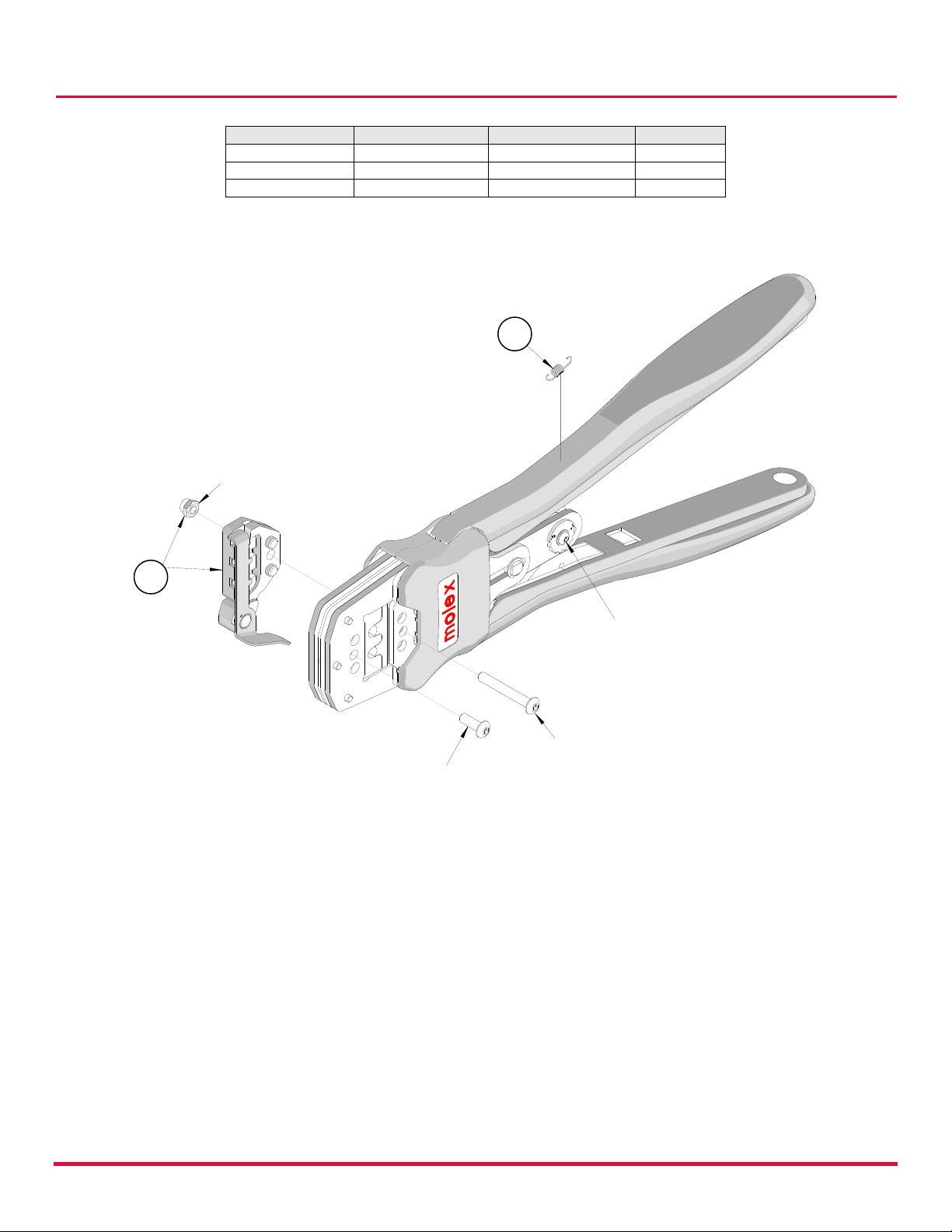
Locator Replacement
See the parts list on the last page of this document for the proper locator order number. Follow the
steps below to replace the locator:
1. Open the hand crimp tool and turn the tool upside down on the back side.
2. Remove the tightening lock nut.
3. Remove the locator assembly from the frame head.
4. To reinstall the new locator, make sure the hand tool is in the open position.
5. Replace the locator assembly into the frame head.
6. Reinstall the tightening lock nut.
Remove and Install Tooling
1. Make sure the tool is in open position before removing or installing tooling.
2. The locator must be removed before removing or installing tooling.
3. Remove the M4 screw that is holding the upper tooling.
4. Remove or install upper tooling through the back side of the tool frame.
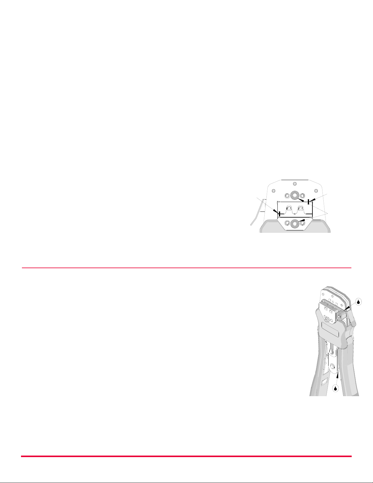
5. Install the M4 screw. Make sure the small markings on the front of the hand tool frame
match up. See Figure 5.
6. Follow steps 3-5 for the lower tooling except through the
front side of the tool frame and install the M3 screw. Be
sure the small markings on the lower tooling line up
with upper tooling.
7. Slowly close the tool handles to align upper and lower
tooling together. Tighten the M4 screws and continue
squeezing the tool handles until the hand tool swings
open.
8. Reinstall the locator by following the instructions in the
locator replacement section.
MAINTENANCE
It is recommended that each operator of the tool be made aware of and responsible for the following
maintenance steps: See Figure 6.
1. Un-snap the 2 Snap-On plastic covers (front and back).
2. Remove dust, moisture and other contaminants with a clean
brush or a soft, lint-free cloth.
3. Do not use any abrasive materials that could damage the tool.
4. Make certain all pins, pivot points and bearing surfaces are
protected with a thin coat of high-quality machine oil. Do not oil
excessively. The tool was engineered for durability, but like any
other equipment, it needs cleaning and lubrication for a maximum
service life of trouble-free crimping. Light oil (such as 30 weight
automotive oil) used at the oil points every 1,000 crimps or 3
months will significantly enhance the tool life.
5. Wipe excess oil from hand tool, particularly from crimping area.
Oil transferred from the crimping area onto certain terminations
may affect the electrical characteristics of an application.
6. When tool is not in use, keep the handles closed to prevent objects from becoming lodged in
the crimping dies, and store the tool in a clean, dry area.