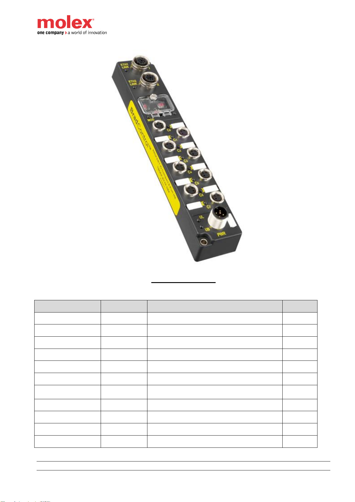
molex Brad HarshIO 300 ePN User manual

HarshIO 300 ePN
i
IP67 Digital I/O Modules for PROFINET IO
User’s Manual
Brad™ HarshIO 300 ePN
IP67 Digital I/O Modules for PROFINET IO
from Molex
Version 2.2
April 8, 2016

HarshIO 300 ePN
ii
IP67 Digital I/O Modules for PROFINET IO
Revision History
Date
Author
Changes
Revision
February 11, 2013
E. GORY
First release
1.0
April 02, 2013
E. GORY
Second release
1.1
May 16, 2013
E. GORY
Add Step7 commissioning chapter
1.2
July 01, 2013
E. GORY
Typo corrections
1.3
September 24, 2013
E. GORY
Add torque for M12 connectors
1.4
February 27,2014
S.Savary
Alarm management –additional information
1.5
April 22,2014
M. Bliss
Add other variants, added note for power on
order (page 6)
1.6
May 15,2014
M. Bliss
Add more information for M12 modules
1.7
May 21, 2014
M. Bliss
Implement feedback from review
1.8
May 23, 2014
M. Bliss
Implement remaining feedback
1.9
June 20, 2014
E. GORY
Typo corrections
2.0

HarshIO 300 ePN
iii
IP67 Digital I/O Modules for PROFINET IO
June 19, 2015
S.Savary
Add web link for Easy replacement procedure
Add grounding info for M12 configurable version
Typo corrections
2.1
June 19, 2015
S.Savary
Max Output current
2.2
Although every effort has been made to ensure the accuracy of this document, all information is subject to
change without notice. Molex takes no liability for any errors in this document or for direct, indirect, or
consequential damage resulting from the use of this manual.

HarshIO 300 ePN
iv
IP67 Digital I/O Modules for PROFINET IO
STATEMENT OF LIMITED WARRANTY
BradControl™ from Molex, manufacturer of HarshIO products, warrants to Buyer that products, except
software, manufactured by BradControl™ will be free from defects in material and workmanship.
BradControl™ obligation under this warranty will be limited to repairing or replacing the defective parts
within one year of the date of installation. Products may be returned by Buyer only after permission has been
obtained from BradControl™. Buyer will prepay all freight charges to return any products to the repair facility
designated by BradControl™.
BradControl™ further warrants that any software supplied as part of a product sale, except obsolete
products, will be free from non-conformances with BradControl™ published specifications for a period of 90
days from the time of delivery. While BradControl™ endeavours to improve the features and performance of
software associated with its products, no effort on the part of BradControl™ to investigate, improve or
modify HarshIO modules firmware at the request of a customer will obligate BradControl™ in any way.
For the convenience of existing customers, BradControl™ continues to supply certain products that are
classified as obsolete. No warranty on the software features of these products is stated or implied and
BradControl™ specifically is not obligated to improve the design of these products in any way. Information
about the status of any product is available upon request and customers are advised to inquire about the
status of older products prior to making a purchase.
This limited warranty does not cover losses or damages which occur in shipment to or from Buyer or due to
improper installation, maintenance, misuse, neglect or any cause other than ordinary commercial or
industrial applications. In particular, BradControl™ makes no warranties whatsoever with respect to implied
warranties of merchantability or fitness for any particular purpose. All such warranties are hereby expressly
disclaimed. No oral or written information or advice given by BradControl™ or BradControl's representative
shall create a warranty or in any way increase the scope of this warranty. This limited warranty is in lieu of all
other warranties whether oral or written, expressed or implied. BradControl’s liability shall not exceed the
price of the individual units, which are the basis of the claim. In no event shall BradControl™ be liable for any
loss of profits, loss of use of facilities or device, or other indirect, incidental or consequential damages.
Although every effort has been made to ensure the accuracy of this document, all information is subject to
change without any notice. BradControl™ takes no liability for any errors in this document or for direct,
indirect, or consequential damage resulting from the use of this manual.
The examples and diagrams in this manual are included solely for illustrative purposes. Because of the many
variables and requirements associated with any particular installation, BradControl™ cannot assume
responsibility or liability for actual use based on the examples and diagrams.
COPYRIGHTS and TRADEMARKS
Reproduction of the contents of this manual, in whole or in part, without written permission of BradControl™
is prohibited.
Mini-Change®, Ultra-Lock™, BradControl™ are all registered trademarks of Molex, Inc.
All other products or trademarks are the property of their respective owners.

HarshIO 300 ePN
v
IP67 Digital I/O Modules for PROFINET IO

HarshIO 300 ePN
vi
IP67 Digital I/O Modules for PROFINET IO
Table of contents
1. General Safety Instructions ................................................................7
General information.................................................................................................7
Personnel qualifications ..........................................................................................7
Preventive messages..............................................................................................7
Usage compliance...................................................................................................8
Device installation and set-up.................................................................................8
Device operation ...................................................................................................10
Electrical, mechanical and thermal specifications.................................................10
Preventive and corrective maintenance................................................................10
2. General description...........................................................................11
Introduction............................................................................................................11
3. System description............................................................................13
Overview ...............................................................................................................13
Typical application.................................................................................................17
4. Module characteristics......................................................................18
Characteristics for M8 versions.............................................................................18
Characteristics for M12 versions...........................................................................20
M8 Mechanical Characteristics .............................................................................25
M12 Mechanical Characteristics ...........................................................................26
Physical I/O mapping ............................................................................................27
Process I/O mapping.............................................................................................29
M8 Pin assignment................................................................................................31
M12 Pin assignment..............................................................................................33
Separate grounding wiring for application using safety relays..............................35
Rotary Switches ....................................................................................................39
5. PROFINET and related functions .....................................................41
Module Configuration Phase.................................................................................41
Module Alarms ......................................................................................................41
Topology Discovery (LLDP) ..................................................................................42
Easy Device Replacement....................................................................................42
6. Configuration using S7 Hardware Manager ....................................43
GSD File................................................................................................................43
Add a HarshIO module..........................................................................................44
Configure a HarshIO device name and IP address ..............................................46
Configure HarshIO module parameters................................................................48
Assigning device name .........................................................................................49
7. Product support.................................................................................51
Product identification.............................................................................................51
Technical support..................................................................................................51
8. Annex..................................................................................................53
PROFINET IO Record...........................................................................................53

HarshIO 300 ePN
7
IP67 Digital I/O Modules for PROFINET IO
1. General Safety Instructions
General information
The current documentation is intended for persons technically qualified to install, use and service the
products described herein. It contains the necessary information for proper use of the products. However,
for advanced use of our products, please contact your nearest dealer for additional information.
The content of this documentation is not binding and cannot extend or limit warranties.
Personnel qualifications
Only qualified persons are authorized to install, use and service the products. Use by unqualified persons or
failure to follow the safety instructions of this document, the manuals and/or those affixed to the devices,
can result in irremediable harm or damage to persons and equipment. The following personnel are deemed
to be qualified persons for:
•Equipment operation: Personnel who operates the machines and/or processes connected to the
Brad™ products. Brad™ HarshIO must be used by persons who have received training and have been
informed of the major risks involved in working in an industrial environment.
•Preventive and corrective maintenance: Persons who modify Brad™ products hardware and software
configuration and install the product updates supplied by the manufacturer. These persons must:
obe trained in Brad™ products and operation and
ohave the experience and technical knowledge required to be aware of the risks (electrical
hazards in particular) involved in their job and the ways of reducing these risks for
themselves, third parties and the equipment being used.
Preventive messages
Preventive messages are designed to identify the particular risks likely to affect personnel and/or hardware.
Different message types, both in the documentation and on the products, indicate different degrees of risk:
Danger messages indicate immediate hazards that could result in death or serious injury if not averted.
Warning messages indicate situations that could result in death, serious injury or material damage.
Caution messages indicate potentially dangerous situations that could cause bodily harm or material
damage.

HarshIO 300 ePN
8
IP67 Digital I/O Modules for PROFINET IO
Usage compliance
The products described in the current documentation comply with currently applicable European Directives
(EC labeling). However, they can only operate correctly with the applications for which they were intended as
described in the documentation, and with approved products.
As a general rule, if all the handling, transportation, and storage recommendations and installation,
operation and maintenance instructions are followed, the products will operate correctly without risk for
personnel or hardware.
Device installation and set-up
It is important to follow the rules below when installing and setting up the Brad™ HarshIO. If system
installation includes products more than thirty meters away from each other, the basic cabling rules must be
closely followed.
•Strict compliance with the safety instructions provided in this documentation or on the equipment to
be installed and implemented, is absolutely essential.
•Make sure that the installation is carried out in compliance with regulations of the user country.
•Install the equipment in a suitable environment. As a closed equipment, the Brad™ HarshIO may be
installed in two ways:
oIn a casing (cabinet, chest) or,
oDirectly without any additional protection, if the associated systems (power supply, cables,
sensors, etc.) already carry a protection index equivalent to IP67 or higher.
oPower cords should be attached to the module before turning the 24V power on. If it isn’t
done in this order then there is a possibility that the module will not power up due to the
added surge protection.
Always connect the Brad™ HarshIO to the protective earth (PE) in compliance with existing standards (for
example: use the green/yellow wires in accordance with the NFC 15 100 standard).
•LV (Low Voltage) circuits must have a protective earth connection to ensure dangerous voltage
detection.
•Before powering up the device, check that the nominal voltage is the same as the mains voltage.
•Only use FELV (Functional Extra Low Voltage) power supplies which comply with existing standards.
•Check that the power voltages are within the tolerance ranges defined in the technical specifications
for the devices.
•Always ensure that power restoration (immediate, hot or cold) will not create a hazard for personnel
or equipment.
•Ensure that emergency stop devices remain effective in any equipment operation mode, even when
abnormal (for example, in the event of a cut wire). Resetting these devices should not result in
uncontrolled or undefined restarts.

HarshIO 300 ePN
9
IP67 Digital I/O Modules for PROFINET IO
•Position the signal cables so that the automation functions will not be disrupted by any capacitive,
inductive or electromagnetic influences, etc.
•Install the automation devices and their controlling devices so that they are protected against any
adverse incident.
•Adequate safety precautions must be applied to inputs and outputs to prevent the lack of signals
from causing undefined states in the automation devices.

HarshIO 300 ePN
10
IP67 Digital I/O Modules for PROFINET IO
Device operation
Because Brad™ HarshIO devices are components of a control system, the safety of the entire automated
system, including that of the installation and the application, cannot be dealt with in this document. For
further information, see IEC 1131-4, describing risk reduction measures for PLC users.
See the documentation of the specific products involved for more information on operation safety.
Electrical, mechanical and thermal specifications
Detailed information about the electrical, mechanical and thermal specifications of the device is available in
the associated technical documentation (installation manuals, service instructions).
Preventive and corrective maintenance
Servicing
•When replacing parts or components, only use factory approved parts.
•In all cases, before servicing a Brad™ HarshIO, disconnect the power supply from the device
(unplug the power cord or open the power cut-out device).
•Before servicing an onsite mechanical Brad™ HarshIO, disconnect its power supply and
mechanically lock the moving parts.
•On positive logic outputs or negative logic inputs, take all the necessary precautions to prevent
any disconnected wires from coming into contact with the mechanical ground (risk of
unwanted commands).
Product end-of-life
Contact your local dealer for information on how to dispose of used products in compliance with
current regulations.

HarshIO 300 ePN
11
IP67 Digital I/O Modules for PROFINET IO
2. General description
Introduction
BradControl™ HarshIO ePN (PROFINET IO) modules provide a reliable solution for connecting industrial
controllers to I/O devices in harsh duty environments. Contained in an IP67 rated housing, BradControl I/O
modules can be machine mounted and are able to withstand areas where liquids, dust or vibration may be
present. This makes them ideally suited for many applications including material handling and automated
assembly.
All BradControl™ HarshIO modules, with Micro-Change®(M12) ports,
accept both standard threaded cordsets and the Molex
Ultra-Lock™ system.
Ultra-Lock™ connection System! The fastest, easiest and most secure
connection ever designed. Ultra-Lock™ technology is designed for
higher performance and reliability. Discover how the push-to-lock
technology of the Ultra-Lock connection system can eliminate your
downtime, increase your productivity and lower your costs. More information visit:
http://www.molex.com/link/ultralock.html .
BradControl™ HarshIO 300 includes advanced diagnostic features. Each module embeds visible LEDs to
provide maintenance personnel the ability to easily determine I/O, module and network status. These
statuses are also available through the process data image or via extended slave diagnostics.
BradControl™ HarshIO 300 main features include:
Module is housed in an IP67 rated enclosure that when properly installed—according to IEC
60529—provides protection against the ingress of dust, water
M8 or M12 I/O connectors
8x digital channels
Support PROFINET real-time (RT) conformance Class-B
I/O update rate from 1ms with a PROFINET controller
Integrated 2-port unmanaged Ethernet switch (with cross-over capability) for daisy chain
topology
Module and Network LEDs (green/red) provides status of module and network
Auxiliary power status LED (green) to indicate power present or low voltage
Each digital I/O channel has a diagnostic LED (green) to indicate I/O status and (red) to indicate
a fault status
Easy commissioning and replacement with 3x rotary switches
Digital input and output short circuit protection
Fixed or user configurable (of input and output channels) according to module version

HarshIO 300 ePN
12
IP67 Digital I/O Modules for PROFINET IO
BradControl™ HarshIO 300 digital modules are available in various combinations:
M8 I/O port versions
8x Inputs
4x Inputs + 4x Outputs
8x Outputs
8x User Configurable Inputs/Outputs
SAP No
Material No
Description
112095-5064
TBDEP-880P-D84-G
IP67 module for PROFINET IO, 8x digital Inputs PNP,
M8 I/O connector, Isolated grounding
112095-5065
TBDEP-844P-D84-G
IP67 module for PROFINET IO, 4x PNP Inputs + 4x Outputs PNP,
M8 I/O connector, Isolated grounding
112095-5066
TBDEP-808P-D84-G
IP67 module for PROFINET IO, 8x Outputs PNP, M8 I/O connector,
Isolated grounding
112095-5067
TBDEP-8YYP-D84
IP67 module for PROFINET IO, 8x User Configurable Inputs/Outputs PNP,
M8 I/O connector
M12 I/O port versions
8x Inputs
4x Inputs + 4x Outputs
8x Outputs
8x User Configurable Inputs/Outputs
SAP No
Material No
Description
112095-5076
TBDEP-480P-D8U-G
IP67 module for PROFINET IO, 8x digital Inputs PNP,
M12 I/O connector, Isolated grounding
112095-5077
TBDEP-444P-D8U-G
IP67 module for PROFINET IO, 4x PNP Inputs + 4x Outputs PNP,
M12 I/O connector, Isolated grounding
112095-5078
TBDEP-408P-D8U-G
IP67 module for PROFINET IO, 8x Outputs PNP, M12 I/O connector,
Isolated grounding
112095-5079
TBDEP-4YYP-D8U
IP67 module for PROFINET IO, 8x User Configurable Inputs/Outputs PNP,
M12 I/O connector
Whatever the combination, the digital Inputs are always PNP (current sink) and Outputs are always PNP
(current source).

HarshIO 300 ePN
13
IP67 Digital I/O Modules for PROFINET IO
3. System description
Overview
HarshIO 300 ePN modules can be used with protocol compliant controllers as part of the control system
architecture. The built-in unmanaged 2-port Ethernet switch allows flexibility in the network topology to
meet your application needs. These topologies include the following:
star
daisy-chain
combination of star and daisy-chain
Star topology
Star topology allows you to connect mixed I/O modules or additional equipment. This topology allows
maintenance on one module –for example, by removing the network cable, or by cycling power to the
module –without affecting the other modules.

HarshIO 300 ePN
14
IP67 Digital I/O Modules for PROFINET IO

HarshIO 300 ePN
15
IP67 Digital I/O Modules for PROFINET IO
Daisy-chain topology
A daisy-chain topology can be created using the module’s embedded switch ports to connect a series
of HarshIO ePN modules.
NOTE: When considering the daisy chain topology
If a module, somewhere in the middle of the chain, has the network cable disconnected or
power to the module is removed then communications to any module located down the chain
will be lost.
The embedded dual port Ethernet switch located in each module eliminates the need for
additional Ethernet switches.

HarshIO 300 ePN
16
IP67 Digital I/O Modules for PROFINET IO
Combination of star and daisy-chain topologies
Combining star and daisy-chain topologies allows you to connect HarshIO ePN modules with mixed
HarshIO modules or additional network devices.

HarshIO 300 ePN
17
IP67 Digital I/O Modules for PROFINET IO
Typical application
This diagram shows you an example of a typical application using an in-cabinet PLC controlling
HarshIO ePN modules that are mounted throughout this industrial system.

HarshIO 300 ePN
18
IP67 Digital I/O Modules for PROFINET IO
4. Module characteristics
Characteristics for M8 versions
Type
8x Inputs
4x Inputs + 4x Outputs
Product Reference
TBDEP-880P-D84-G
TBDEP-844P-D84-G
PROFINET Identification
Vendor ID: 0x0127
Device ID: 0x1008
DAP identifier: 0x40110008
Vendor ID: 0x0127
Device ID: 0x1008
DAP identifier: 0x40110404
Power
Power connector
M12 Ultra-Lock, 5-pin, male, A-Coded, stainless steel
Module & Input power (UB)
24 VDC, -15/+20% (protected against power crossing)
Warning, a voltage over 30 VDC will destroy the module
Operating current (UB)
68 mA
Output power (UL)
Not Applicable
24 VDC, -15/+20%
(protected against power crossing)
Operating current (UL)
Not Applicable
10 mA (without load)
Inputs
Channels
8x channels, 2 or 3-wire
4x channels, 2 or 3-wire
Connector
M8, 3-pin, female, stainless steel
Input type
PNP, Sinking
On-state current
1-8mA maximum
Max off state current
300µA
Input voltage
UB
Sensor power supply (max)
250 mA at 25°C
Input channel voltage (“1”)
10V … 25V
Input channel voltage (“0”)
-0.2V … 5V
Input short circuit
protection (per port)
600mA
Switching frequency
min of 100Hz
Input filter
0.5 3 ms (default 1 ms)
Outputs
Channels
Not Applicable
4x channels, 2-wire
Output voltage
Not Applicable
UL - 1 VDC
Connector
Not Applicable
M8, 3-pin, female, stainless steel
Output type
Not Applicable
PNP, Sourcing
Output current
Not Applicable
1.4 A per channel, max. 4A total
Maximum output current
Not Applicable
4.0 A at 25°C ; total for all outputs combined
Short circuit current (typical)
Not Applicable
up to 6.5 A
Switching frequency
Not Applicable
200 Hz

HarshIO 300 ePN
19
IP67 Digital I/O Modules for PROFINET IO
Type
8x Outputs
8x User Configurable Inputs/Outputs
Product Reference
TBDEP-808P-D84-G
TBDEP-8YYP-D84
PROFINET Identification
Vendor ID: 0x0127
Device ID: 0x1008
DAP identifier: 0x40110800
Vendor ID: 0x0127
Device ID: 0x1008
DAP identifier: 0x40110808
Power
Power connector
M12 Ultra-Lock, 5-pin, male, A-Coded, stainless steel
Module & Input power (UB)
24 VDC, -15/+20% (protected against power crossing)
Warning, a voltage over 30 VDC will destroy the module
Operating current (UB)
68 mA
Output power (UL)
24 VDC, -15/+20%
(protected against power crossing)
Operating current (UL)
10 mA (without load)
Inputs
Channels
Not Applicable
Up to 8x channels, 2 or 3-wire
Connector
Not Applicable
M8, 3-pin, female, stainless steel
Input type
Not Applicable
PNP, Sinking
On-state current
Not Applicable
1-8mA maximum
Max off state current
Not Applicable
300µA
Input voltage
Not Applicable
UB
Sensor power supply (max)
Not Applicable
250 mA at 25°C
Input channel voltage (“1”)
Not Applicable
10V … 25V
Input channel voltage (“0”)
Not Applicable
-0.2V … 5V
Input short circuit
protection (per port)
Not Applicable
600mA
Switching frequency
Not Applicable
min of 100Hz
Input filter
Not Applicable
0.5 3 ms (default 1 ms)
Outputs
Channels
8x channels, 2-wire
Up to 8x channels, 2-wire
Output voltage
UL - 1 VDC
Connector
M8, 3-pin, female, stainless steel
Output type
PNP, Sourcing
Output current
1.4 A per channel, max. 4A total
Maximum output current
4.0 A at 25°C ; total for all outputs combined
Short circuit current (typical)
up to 6.5 A
Switching frequency
200 Hz

HarshIO 300 ePN
20
IP67 Digital I/O Modules for PROFINET IO
Characteristics for M12 versions
Type
8x Inputs
4x Inputs + 4x Outputs
Product Reference
TBDEP-480P-D8UG
TBDEP-444P-D8U-G
PROFINET Identification
Vendor ID: 0x0127
Device ID: 0x1008
DAP identifier: 0x50110008
Vendor ID: 0x0127
Device ID: 0x1008
DAP identifier: 0x50110404
Power
Power connector
M12 Ultra-Lock, 5-pin, male, A-Coded, stainless steel
Module & Input power (UB)
24 VDC, -15/+20% (protected against power crossing)
Warning, a voltage over 30 VDC will destroy the module
Operating current (UB)
68 mA
Output power (UL)
Not Applicable
24 VDC, -15/+20%
(protected against power crossing)
Operating current (UL)
Not Applicable
10 mA (without load)
Inputs
Channels
8x channels, 2 or 3-wire
4x channels, 2 or 3-wire
Connector
M12, 5-pin, female, stainless steel
Input type
PNP, Sinking
On-state current
1-8mA maximum
Max off state current
300µA
Input voltage
UB
Sensor power supply (max)
250 mA at 25°C
Input channel voltage (“1”)
10V … 25V
Input channel voltage (“0”)
-0.2V … 5V
Input short circuit
protection (per port)
600mA
Switching frequency
min of 100Hz
Input filter
0.5 3 ms (default 1 ms)
Outputs
Channels
Not Applicable
4x channels, 2-wire
Output voltage
Not Applicable
UL - 1 VDC
Connector
Not Applicable
M8, 3-pin, female, stainless steel
Output type
Not Applicable
PNP, Sourcing
Output current
Not Applicable
1.4 A per channel, max. 4A total
Maximum output current
Not Applicable
4.0 A at 25°C ; total for all outputs combined
Short circuit current (typical)
Not Applicable
up to 6.5 A
Switching frequency
Not Applicable
200 Hz
Table of contents
Other molex Network Hardware manuals