Monaco security IRS-100 User manual

Infrarot-Reflexionslicht-
schranke
Bitte lesen Sie diese Bedienungsanleitung vor der
Installation und dem Betrieb gründlich durch und
heben Sie sie für ein späteres Nachlesen auf.
1 Einsatzmöglichkeiten
Diese Reflexionslichtschranke dient der Erfassung von
Personen oder Objekten z. B. zur Überwachung von
Gebäudeeingängen und Grundstückszufahrten oder
zu Steuerungszwecken. Sie arbeitet mit Infrarotlicht
bei einem Reflektorabstand von 20 cm bis 14 m. Bei
einer Unterbrechung des Lichtstrahls auf dem Weg
vom Sender (10) über den Reflektor (1) bis zum Emp-
fänger (9) wird ein Relais mit Umschaltkontakt aus-
gelöst. Durch ihr wetterfestes Gehäuse (IP 66) ist die
Lichtschranke auch für Außeninstallationen geeignet.
2 Hinweise für den sicheren Gebrauch
Die Lichtschranke entspricht allen erforderlichen Richt-
linien der EU und ist deshalb mit gekennzeichnet.
●Das Gerät ist wettergeschützt, jedoch nicht absolut
wasserdicht. Tauchen Sie es darum nicht in Wasser
ein.
●Betreiben Sie die Lichtschranke nicht in Bereichen
mit extremen Temperaturen (zulässiger Einsatztem-
peraturbereich
-
20 °C bis +55 °C).
●Verwenden Sie für die Reinigung keine scharfen
Reinigungsmittel oder Chemikalien.
●Wird die Lichtschranke zweckentfremdet, falsch
installiert oder nicht fachgerecht repariert, kann
keine Haftung für daraus resultierende Sach- oder
Personenschäden und keine Garantie für die Licht-
schranke übernommen werden.
3 Installation
Die Installation sollte nur durch qualifiziertes Fachper-
sonal durchgeführt werden.
Hinweise zum Montageort:
– Werden mehrere Lichtschranken eingesetzt, diese
so montieren, dass sie sich nicht gegenseitig
beeinflussen.
– Bei Objekten mit reflektierender Oberfläche sollte
die Lichtschranke so montiert werden, dass die
Soll die Lichtschranke endgültig aus dem
Betrieb genommen werden, übergeben Sie
sie zur umweltfreundlichen Entsorgung
einem örtlichen Recyclingbetrieb.
Objekte den Infrarotlichtstrahl schräg durchlaufen,
da sie sonst eventuell nicht erkannt werden.
– Bei der Installation im Freien den Montageort so
wählen, dass Fehlauslösungen (z. B. durch wind-
bewegte Pflanzen oder herumlaufende Tiere) mög-
lichst vermieden werden.
3.1 Montage und Anschluss
1) Den Reflektor (1) mit einer Schraube und die
Sende- und Empfangseinheit (5) mit ihrer Monta-
gehalterung zunächst provisorisch so montieren,
dass sie zueinander zeigen. Dabei beachten, dass
der Abstand zueinander mindestens 20 cm und
höchstens 14 m beträgt.
2) Die Sende-/Empfangseinheit an eine Versor-
gungsspannung anschließen. Die Belegung der
Adern des Anschlusskabels (6) ist in der Abbildung
beschrieben. Als Versorgung kann eine Wechsel-
spannung oder eine Gleichspannung 12 – 48 V die-
nen (die Polung ist beim Anschluss an eine Gleich-
spannungsquelle unerheblich).
3) Ein Gerät zur Auswertung der Lichtstrahlunterbre-
chung (z. B. Signalgeber, Alarmanlage, Zähleinrich-
tung) an die in der Abbildung aufgeführten Relais-
kontakte anschließen. Dabei darauf achten, dass
die maximale Kontaktbelastbarkeit von 48 V~/3 A
und 30 V /3 A nicht überschritten wird.
3.2 Ausrichten der Lichtschranke
Zur Anzeige des Betriebszustandes ist die Sende-/
Empfangseinheit mit zwei LEDs ausgestattet, die das
Ausrichten der Lichtschranke erleichtern. Die gelbe
LED (7) leuchtet, wenn die Lichtschranke richtig aus-
gerichtet ist. Die rote LED (8) leuchtet, wenn die
Sende-/Empfangseinheit und der Reflektor nicht rich-
tig aufeinander ausgerichtet sind, die Entfernung des
Reflektors zur Sende-/Empfangseinheit zu groß ist
oder der Lichtstrahl unterbrochen wird.
1) Die Abdeckklappe (4) nach oben aufklappen.
2) Das Trimmpotentiometer „Sensing Range“ (2) mit
einem kleinen Schraubendreher auf Rechtsan-
schlag stellen.
3) Den Reflektor so ausrichten, dass die gelbe LED
leuchtet, wenn der Lichtstrahl nicht unterbrochen
wird.
4) Gegebenenfalls auch die Ausrichtung der Sende-/
Empfangseinheit korrigieren.
5) Ist die Lichtschranke optimal ausgerichtet, die end-
gültige Befestigung vornehmen.
3.3 Empfindlichkeit einstellen
Mit dem Trimmpotentiometer „Sensing Range“ (2) kann
eingestellt werden, wie empfindlich die Lichtschranke
auf eine Unterbrechung des Lichtstrahls reagieren soll.
Ist eine geringe Empfindlichkeit eingestellt, kann
die Lichtschranke auch schon bei sehr kleinen Objek-
ten, die den Lichtstrahl unterbrechen, auslösen. Ist
eine hohe Empfindlichkeit eingestellt, werden kleine
Objekte von der Lichtschranke ignoriert.
1) Das Trimmpotentiometer für die Empfindlichkeit (2)
auf Linksanschlag drehen.
2) Wenn die gelbe LED (7) noch nicht leuchtet, das
Trimmpotentiometer langsam soweit aufdrehen,
bis sie zu leuchten beginnt.
3) Jetzt das Objekt, was erkannt werden soll, an der
Stelle, wo es gewöhnlich den Lichtstrahl durch-
kreuzen wird, durch den Lichtstrahl bewegen. Die
rote LED (8) sollte in diesem Moment anstelle der
gelben aufleuchten.
4) Das Trimmpotentiometer langsam im Uhrzeiger-
sinn weiter drehen, bis wieder die gelbe LED leuch-
tet. Bei größeren Objekten schalten die LEDs nicht
mehr um, bis der Rechtsanschlag erreicht ist.
5) Die empfohlene Einstellung der Empfindlichkeit für
einen zuverlässigen Betrieb ist nun die Mittelstel-
lung zwischen den beiden unter 2) und 4) ermittel-
ten Potentiometerpositionen, bei denen die LED-
Umschaltungen erfolgten (bzw. dem jeweiligen
Endanschlag, wenn keine Umschaltung stattgefun-
den hat).
3.4 Ansprechzeit einstellen
Mit dem Potentiometer „Response Time“ (3) kann im
Bereich 5 – 100 ms eingestellt werden, wie lange der
Lichtstrahl unterbrochen werden muss, damit das
Relais auslöst.
Nach erfolgter Einstellung die Abdeckklappe (4) zum
Schutz der Potentiometer wieder schließen.
4 Technische Daten
Reflektorabstand: . . . . . . . 0,2 – 14 m
Relais
Ansprechzeit: . . . . . . . . 5 – 100 ms einstellbar
Kontaktbelastbarkeit: . . 48 V~/3 A
30 V /3 A
Einsatztemperatur: . . . . . .
-
20 °C bis +55 °C
Spannungsversorgung:. . . 12 – 48 V~
oder 12 – 48 V
Stromaufnahme: . . . . . . . . 65 mA ±10 %
Schutzart: . . . . . . . . . . . . . IP 66
Änderungen vorbehalten.
IRS-100 Best.-Nr. 04.2940
Copyright©by MONACOR INTERNATIONAL GmbH & Co. KG, Bremen, Germany. All rights reserved. A-0413.99.03.11.2007
®
2 m
20 mm
51 mm
39 mm
Ø 81 mm
7 mm
0,2 – 14 m
29 mm
63 mm
1
23
6
4
5
7
8
9
10
braun
blau
schwarz
Relais
Versorgung
12 – 48 V~
oder
12 – 48 V
n.o.
n.c. grau
weiß
D A CH

Infrared Reflection Light Barrier
Please read these operating instructions carefully prior
to the installation and operation and keep them for later
use.
1 Applications
This reflection light barrier serves for detecting per-
sons or objects, e. g. for security surveillance of en-
trance doors, gates and driveways, or for control pur-
poses. The light barrier operates with infrared light at
a reflector distance of 20 cm to 14 m. When the light
beam is interrupted on its way from the transmitter (10)
via the reflector (1) to the receiver (9), a relay with
change-over contact will respond. Due to its weather-
proof housing (IP 66), the light barrier is also suitable
for outdoor installation.
2 Safety Notes
The reflection light barrier corresponds to all required
directives of the EU and is therefore marked with .
●The unit is weatherproof, however, not completely
waterproof. Therefore, do not immerse it in water.
●Do not operate the light barrier in areas of extreme
temperatures (admissible ambient temperature
range
-
20 °C to +55 °C).
●For cleaning do not use aggressive detergents or
chemicals.
●No guarantee claims for the light barrier and no lia-
bility for any resulting personal damage or material
damage will be accepted if the light barrier is used
for other purposes than originally intended, if it is not
correctly installed, or not repaired in an expert way.
3 Installation
The light barrier should be installed by skilled person-
nel only.
Notes concerning the place of installation:
– When using several light barriers, install them in such
a way that they will not interfere with one another.
– For objects with a reflective surface, the light barri-
er should be installed in such a way that the objects
will pass through the infrared light beam at an
angle, otherwise they may not be detected.
If the light barrier is to be put out of operation
definitively, take it to a local recycling plant for
a disposal which is not harmful to the envi-
ronment.
– For outdoor installation, choose a place of installa-
tion where it is not likely that false alarms (e. g. trig-
gered by plants moving in the wind or animals run-
ning around) will occur.
3.1 Mounting and connection
1) For the time being, provisionally install the reflector
(1) with a screw and the transmitter/receiver unit (5)
with its mounting support in such a way that they
will face each other. Observe the required distance
between them: minimum distance 20 cm and maxi-
mum distance 14 m.
2) Connect the transmitter/receiver unit to a supply
voltage. You will find the core configuration of the
connection cable (6) in the figure below. As a power
supply, a 12 – 48 V~ voltage or a 12 – 48 V volt-
age can be used (when connecting the unit to a DC
voltage source, the polarity is negligible).
3) Connect a unit for evaluating the interruption of the
light beam (e. g. signal device, alarm system, coun-
ting device) to the relay contacts shown in the figu-
re below. Make sure that the maximum contact
rating of 48 V~/3 A and 30 V /3 A will not be
exceeded.
3.2 Aligning the light barrier
To indicate the operating state, the transmitter/re-
ceiver unit is equipped with two LEDs which will facili-
tate the alignment of the light barrier. The yellow LED
(7) will light up if the light barrier is correctly aligned.
The red LED (8) will light up if the transmitter/receiver
unit and the reflector are not correctly aligned to each
other, if the reflector and the transmitter/receiver unit
are too far apart, or if the light beam is interrupted.
1) Unfold the cover plate (4) upwards.
2) Set the trimming potentiometer “Sensing Range”
(2) to the right stop with a small screwdriver.
3) Align the reflector in such a way that the yellow LED
will light up when the light beam is not interrupted.
4) Also realign the transmitter/receiver unit, if required.
5) After optimum alignment of the light barrier, fasten
it definitively.
3.3 Adjusting the sensitivity
The trimming potentiometer “Sensing Range” (2) al-
lows to adjust the desired sensitivity of the light barrier
for responding to an interruption of the light beam.
With a low sensitivity adjusted, the light barrier will
already be triggered when very small objects interrupt
the light beam. With a high sensitivity adjusted, the
light barrier will ignore small objects.
1) Set the trimming potentiometer for the sensitivity (2)
to the left stop.
2) If the yellow LED (7) does not light up yet, slowly
turn the trimming potentiometer until it starts light-
ing up.
3) Move the object to be detected through the light
beam at the place where it will usually pass through
it. At this moment, the red LED (8) should light up
instead of the yellow one.
4) Slowly turn the trimming potentiometer clockwise
until the yellow LED lights up again. With larger
objects, the LEDs will not change again until the
potentiometer is at the right stop.
5) The sensitivity adjustment recommended for a
reliable operation is the mid-position between the
two potentiometer positions determined under 2)
and 4) where the LEDs changed (or the respective
stop if there was no change of LEDs).
3.4 Adjusting the response time
In the range of 5 to 100 ms, the potentiometer “Re-
sponse Time” (3) allows to adjust how long the light
beam must be interrupted so that the relay will re-
spond.
After the adjustment close the cover plate (4) to pro-
tect the potentiometers.
4 Specifications
Reflector distance: . . . . . . 0.2 – 14 m
Relay
Response time:. . . . . . . adjustable
from 5 to 100 ms
Contact rating:. . . . . . . . 48 V~/3 A
30 V /3 A
Ambient temperature: . . . .
-
20 °C to +55 °C
Power supply: . . . . . . . . . . 12 – 48 V~
or 12 – 48 V
Current consumption: . . . . 65 mA ±10 %
Class of protection: . . . . . . IP 66
Subject to technical modification.
IRS-100 Order No. 04.2940
Copyright©by MONACOR INTERNATIONAL GmbH & Co. KG, Bremen, Germany. All rights reserved. A-0413.99.03.11.2007
®
2 m
20 mm
51 mm
39 mm
Ø 81 mm
7 mm
0,2 – 14 m
29 mm
63 mm
1
23
6
4
5
7
8
9
10
brown
blue
black
Relay
Power supply
12–48V~
or
12–48V
n.o.
n.c. grey
white
GB

Barrière lumineuse
infrarouge à réflexion
Veuillez lire la présente notice avec attention avant
l'installation et le fonctionnement et conservez-la pour
pouvoir vous y reporter ultérieurement.
1 Possibilités d’utilisation
La barrière lumineuse à réflexion permet de détecter
des personnes ou objets par exemple pour la surveil-
lance d’entrées de bâtiments, accès ou à des fins de
contrôle. Elle fonctionne avec une lumière infrarouge
avec une distance du réflecteur de 20 cm à 14 m. En
cas d’interruption du rayon lumineux sur le chemin
allant de l’émetteur (10) au récepteur (9) via le réflec-
teur (1), un relais avec contact de commutation est
déclenché. Grâce au boîtier résistant aux intempéries
(IP 66), la barrière est également adaptée pour des
installations en extérieur.
2 Conseils d’utilisation et de sécurité
La barrière répond à toutes les directives nécessaires
de l’Union Européenne et porte donc le symbole .
●La barrière est protégée contre les intempéries mais
n’est pas complètement étanche. Ne la plongez
jamais dans l’eau.
●Ne faites pas fonctionner la barrière dans des zones
soumises à des températures extrêmes (plage de
température de fonctionnement autorisée
-
20 °C à
+55 °C).
●Pour le nettoyage, n’utilisez pas de produits chimi-
ques ou de détergents.
●Nous déclinons toute responsabilité en cas de dom-
mages corporels ou matériels résultants si la barriè-
re est utilisée dans un but autre que celui pour lequel
elle a été conçue, si elle n’est pas correctement
installée ou n’est pas réparée par une personne
habilitée, de même, la garantie deviendrait caduque.
3 Installation
Seul un personnel qualifié devrait effectuer l’installation.
Conseil pour le lieu de montage :
– Si plusieurs barrières sont utilisées, montez-les de
telle sorte qu’elles ne puissent pas interférer les
unes avec les autres.
– Pour des objets avec une surface réfléchissante, il
faudrait monter la barrière de telle sorte que les
objets passent à travers le rayon lumineux infra-
Lorsque la barrière lumineuse est définitive-
ment retirée du service, vous devez le dépo-
ser dans une usine de recyclage adaptée pour
contribuer à son élimination non polluante.
rouge dans un angle sinon ils pourraient ne pas
être détectés.
– Dans le cas d’une installation à l’air libre, le lieu de
montage doit être sélectionné de telle sorte que les
fausses alarmes (causées p. ex. par des plantes
que le vent fait bouger ou des animaux se dé-
plaçant) puissent être évitées autant que possible.
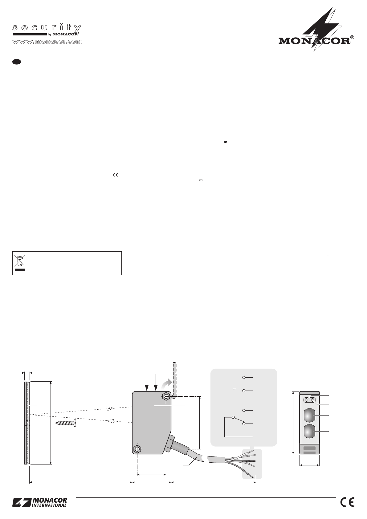
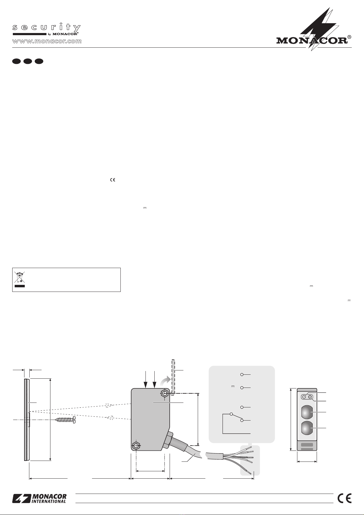
3.1 Montage et branchement
1) Pour le moment, installez provisoirement le réflec-
teur (1) avec une vis et l'unité émetteur/récepteur
(5) avec son support de montage de telle sorte
qu'ils se fassent face. Veillez à ce que la distance
entre eux soit de 20 cm au moins et de 14 m au
plus.
2) Reliez l’unité émetteur/récepteur à une tension
d’alimentation. La configuration des conducteurs
du câble de branchement (6) est décrite sur le
schéma. Comme alimentation, on peut utiliser une
tension alternative ou une tension continue 12 –
48 V (la polarité lors du branchement à une source
de tension DC est insignifiante).
3) Reliez un appareil pour évaluer l’interruption du
rayon lumineux (par exemple émetteur de signal,
centrale d’alarme, compteur) aux contacts des
relais présentés sur le schéma. Veillez à ce que la
puissance maximale de contact de 48 V~/3 A et
30 V /3 A ne soit pas dépassée.
3.2 Alignement de la barrière lumineuse
Pour indiquer l’état de fonctionnement, l’unité émet-
teur/récepteur est dotée de deux LEDs qui facilitent
l’alignement de la barrière. La LED jaune (7) brille si la
barrière est correctement alignée. La LED rouge (8)
brille si l’unité émetteur/récepteur et le réflecteur ne
sont pas correctement alignés l’un par rapport à l’au-
tre, si l’éloignement du réflecteur avec l’unité émet-
teur/récepteur est trop grand ou si le rayon lumineux
est interrompu.
1) Dépliez la plaque couvercle (4) vers le haut.
2) Mettez le potentiomètre trimmer “Sensing Range”
(2) sur la butée de droite avec un petit tournevis.
3) Alignez le réflecteur de telle sorte que la LED jaune
brille si le rayon lumineux n’est pas interrompu.
4) Si besoin, corrigez également l’alignement de l’u-
nité émetteur/récepteur.
5) Si la barrière est alignée de manière optimale,
procédez au montage définitif.
3.3 Réglage de la sensibilité
Avec le réglage trimmer “Sensing Range” (2), on peut
régler l’intensité avec laquelle la barrière doit réagir en
cas de coupure du rayon lumineux.
Si une sensibilité faible est réglée, la barrière peut
déclencher même pour des objets très petits coupant
le rayon lumineux. Si une sensibilité élevée est réglée,
les petits objets sont ignorés par la barrière.
1) Tournez le potentiomètre trimmer de la sensibilité (2)
sur la butée de gauche.
2) Si la LED jaune (7) ne brille pas encore, tournez le
potentiomètre trimmer lentement jusqu’à ce qu’elle
commence à briller.
3) Faites passer l’objet à détecter à travers le rayon
lumineux, à l’endroit où il va le traverser habituelle-
ment. La LED rouge (8) devrait à cet instant-là, bril-
ler à la place de la jaune.
4) Tournez lentement le potentiomètre trimmer dans
le sens des aiguilles d’une montre jusqu’à ce que la
LED jaune brille à nouveau. Pour des objets plus
grands, les LEDs ne changent plus jusqu’à ce que
la butée de droite soit atteinte.
5) Le réglage recommandé de la sensibilité, pour un
fonctionnement fiable, est la position médiane
entre les deux positions du potentiomètre déter-
minées aux points 2) et 4), où les LEDs changent
(ou à la butée correspondante s’il n’y a pas de
changement de LEDs).
3.4 Réglage du temps de réponse
Avec le potentiomètre trimmer “Response Time” (3),
on peut régler, dans la plage 5 – 100 ms, la durée pen-
dant laquelle le faisceau lumineux doit être interrompu
pour que le relais se déclenche.
Une fois le réglage effectué, refermez la plaque cou-
vercle (4) pour protéger les potentiomètres.
4 Caractéristiques techniques
Distance réflecteur : . . . . . 0,2 –14 m
Relais
Temps de réponse : . . . 5 – 100 ms réglable
Puissance contacts :. . . 48 V~/3 A
30 V /3 A
Température fonc. : . . . . . .
-
20 °C à +55 °C
Tension alimentation : . . . . 12 – 48 V~ ou 12 – 48 V
Consommation : . . . . . . . . 65 mA ±10 %
Classe protection : . . . . . . IP 66
Tout droit de modification réservé.
IRS-100 Ref. num. 04.2940
Copyright©by MONACOR INTERNATIONAL GmbH & Co. KG, Bremen, Germany. All rights reserved. A-0413.99.03.11.2007
®
2 m
20 mm
51 mm
39 mm
Ø 81 mm
7 mm
0,2 – 14 m
29 mm
63 mm
1
23
6
4
5
7
8
9
10
marron
bleu
noir
Relais
Alimentation
12 – 48 V~
ou
12 – 48 V
n.o.
n.c. gris
blanc
F B CH

Fotocellula IR a riflessione su
catarifrangente
Vi preghiamo di leggere attentamente le presenti istru-
zioni prima dell'installazione e della messa in funzione
e di conservarle per un uso futuro.
1 Possibilità d’impiego
Questa fotocellula a riflessione su catarifrangente
serve per rilevare persone o oggetti, per esempio per
la sorveglianza di ingressi in edifici e di accessi a ter-
reni, ma anche per comandare altri dispositivi. Funzio-
na con luce infrarossa con una distanza del catarifran-
gente da 20 cm a 14 m. Un’interruzione del raggio di
luce che va dal proiettore (10) al catarifrangente (1) e
ritorna quindi al ricevitore (9), fa scattare un relè con
contatto di commutazione. Grazie al contenitore resi-
stente alle intemperie (IP 66), la fotocellula è adatta
anche per l’installazione esterna.
2 Avvertenze di sicurezza
La fotocellula è conforme a tutte le direttive richieste
dell’UE e pertanto porta la sigla .
●Lo strumento è resistente alle intemperie, ma non a
tenuta assoluta d’acqua. Non immergerlo nell’acqua.
●Non usare la fotocellula in ambienti con temperatu-
re estreme (temperatura d’esercizio ammessa
-
20 °C a +55 °C).
●Per la pulizia non impiegare detersivi aggressivi o
prodotti chimici.
●Nel caso d’uso improprio, d’installazione sbagliata o
di riparazione non a regola d’arte della fotocellula,
non si assume nessuna responsabilità per eventua-
li danni consequenziali a persone o a cose e non si
assume nessuna garanzia per la fotocellula.
3 Installazione
L’installazione dovrebbe essere effettuata solo da per-
sonale specializzato e qualificato.
Alcuni cenni sul luogo di montaggio:
– Se si installano più fotocellule, montarle in modo
tale da escludere interferenze.
– Nel caso di oggetti con superficie riflettente, la foto-
cellula dovrebbe essere montata in modo tale che
gli oggetti attraversino il raggio di luce infrarossa in
Se si desidera eliminare la fotocellula de-
finitivamente, consegnarla per lo smaltimen-
to ad un’istituzione locale per il riciclaggio.
posizione inclinata perché altrimenti potrebbero
non essere rilevati.
– Nel caso di installazione all’aperto scegliere il luogo
di montaggio in modo tale da escludere il più pos-
sibile scatti falsi (p. es. da piante mosse dal vento e
da animali).
3.1 Montaggio e collegamento
1) Montare in modo provvisorio il riflettore (1) con una
vite e l'unita proiettore/ricevitore (5) con il suo sup-
porto per il montaggio in modo che siano rivolti
l'uno verso l'altra. Fare attenzione che la distanza
fra di loro non sia inferiore a 20 cm e non superiore
a 14 m.
2) Collegare l’unità proiettore/ricevitore con una ten-
sione di alimentazione. I contatti per i conduttori del
cavo di collegamento (6) sono indicati nell’illustra-
zione. Come alimentazione è possibile un’alimen-
tazione alternata oppure una tensione continua
12 – 48 V (nel caso di una sorgente di tensione con-
tinua, la polarità non ha importanza).
3) Collegare un dispositivo per la valutazione dell’in-
terruzione del raggio di luce (p. es. segnalatore,
impianto d’allarme, contatore) con i contatti relè in-
dicati nell’illustrazione. Fare attenzione che la po-
tenza massima dei contatti di 48 V~/3 A e 30 V /
3 A non venga superata.
3.2 Puntamento della fotocellula
Per indicare lo stato di funzionamento, l’unità proietto-
re/ricevitore è equipaggiata con due LED che facilita-
no il puntamento della fotocellula. Il LED giallo (7) si
accende se la fotocellula è orientata correttamente. Il
LED rosso (8) si accende, se l’unità proietto-
re/ricevitore e il catarifrangente non sono orientati cor-
rettamente, se la distanza del catarifrangente dall’u-
nità proiettore/ricevitore è troppo grande o se il raggio
di luce viene interrotto.
1) Ribaltare verso l'alto il coperchio (4).
2) Girare il potenziometro “Sensing Range” (2) fino
all'arresto a destra servendosi di un piccolo caccia-
vite.
3) Orientare il catarifrangente in modo tale che il LED
giallo si accende se il raggio di luce non viene inter-
rotto.
4) Eventualmente correggere anche l’orientamento
dell’unità proiettore/ricevitore.
5) Se la fotocellula è orientata in modo ottimale, pro-
cedere al fissaggio definitivo.
3.3 Impostare la sensibilità
Con il potenziometro “Sensing Range” (2) è possibile
regolare la sensibilità della fotocellula di fronte ad
un’interruzione del raggio di luce.
Nel caso di sensibilità bassa, la fotocellula scatta
anche con oggetti molto piccoli che interrompono il
raggio di luce. Se è impostata una sensibilità alta, gli
oggetti piccoli non vengono rilevati dalla fotocellula.
1) Girare il potenziometro per la sensibilità (2) tutto a
sinistra.
2) Se il LED giallo (7) non si accende ancora, aprire il
potenziometro lentamente finché non inizi ad
accendersi.
3) A questo punto muovere l’oggetto da rilevare nel
punto del raggio di luce dove lo attraverserà abi-
tualmente. In quel momento si dovrebbe accende-
re il LED rosso (8) al posto di quello giallo.
4) Continuare a girare il potenziometro lentamente in
senso orario fino alla nuova accensione del LED
giallo. Con oggetti più grandi, i LED non cambiano
più fino al raggiungimento della posizione tutta a
destra.
5) L’impostazione della sensibilità consigliata per il
corretto funzionamento è costituita dalla posizione
centrale fra le due posizioni del potenziometro rile-
vate ai punti 2) e 4), dove i LED cambiavano (oppu-
re all’arresto finale se non si verificava nessun
cambiamento del colore dei LED).
3.4 Impostare il tempo di reazione
Con il potenziometro “Response Time” (3) è possibile
impostare, fra 5 – 100 ms, la durata dell'interruzione
del raggio di luce che fa scattare il relé.
Al termine dell'impostazione richiudere il coperchio (4)
per proteggere i potenziometri.
4 Dati tecnici
Distanza catarifrangente: . 0,2 – 14 m
Relè
Tempo di reazione: . . . . 5 – 100 ms regolabile
Potenza dei contatti: . . . 48 V~/3 A
30 V /3 A
Temperatura d’esercizio:. .
-
20 °C a +55 °C
Alimentazione: . . . . . . . . . 12 – 48 V~
o 12 – 48 V
Assorbimento: . . . . . . . . . . 65 mA ±10 %
Protezione: . . . . . . . . . . . . IP 66
Con riserva di modifiche tecniche.
IRS-100 N. articolo 04.2940
Copyright©by MONACOR INTERNATIONAL GmbH & Co. KG, Bremen, Germany. All rights reserved. A-0413.99.03.11.2007
®
2 m
20 mm
51 mm
39 mm
Ø 81 mm
7 mm
0,2 – 14 m
29 mm
63 mm
1
23
6
4
5
7
8
9
10
marron
blu
nero
Relè
Alimentazione
12–48V~
o
12–48V
n.o.
n.c. grigio
bianco
I

Barrera de reflejo de luz infrarroja
Por favor, lea estas instrucciones de funcionamiento
atentamente antes de la instalación y la utilización y
guárdelas para usos posteriores.
1 Aplicaciones
Esta barrera de reflejo de luz sirve para detectar per-
sonas y objetos, por ejemplo para los controles de
seguridad en las entradas de recintos, puertas y los
caminos de entrada, o para finalidades de control. La
barrera de luz funciona con luz infrarroja con una
distancia de reflector entre 20 cm a 14 m. Cuando el
rayo de luz se interrumpe desde el transmisor (10) a
través del reflector (1) al receptor (9), va a responder
un relé con contacto alternado. Por su recinto re-
sistente a la intemperie (IP 66), la barrera de luz tam-
bién puede utilizarse en el exterior.
2 Notas de seguridad
La barrera de reflejo de luz corresponde a todas las
Directivas requeridas por la UE y por ello está marca-
da con .
●La unidad es resistente a la intemperie, no obstan-
te, no es completamente impermeable. Es por esto
que no debe sumergirla en el agua.
●No haga funcionar la barrera de luz en zonas con
temperaturas extremas (temperatura de ambiente
admisible de
-
20 °C a +55 °C).
●Para limpiarla no utilice detergentes agresivos o
químicos.
●La barrera de luz carecería de todo tipo de garantía
y no nos responsabilizamos en caso de daños per-
sonales o materiales si la barrera de luz se ha uti-
lizado con otro fin del que le ha sido concebido, si no
está instalada correctamente o reparada por perso-
nal autorizado.
3 Instalación
La barrera de luz únicamente debería ser instalada
por personal autorizado.
Notas en relación al lugar de instalación:
– Cuando utilice varias barreras de luz instálelas de
manera que no interfieran las unas con las otras.
– Para objetos con una superficie reflectora, la barre-
ra de luz debería instalarse de manera que los
Si la barrera de luz está definitivamente reti-
rada del servicio, deposítela en una fábrica
de reciclaje próxima para contribuir a su eli-
minación no contaminante.
objetos pasen a través del rayo de la luz infrarroja
diagonalmente, si no es así podrían no detectarse.
– Para una utilización en exterior, escoja un lugar de
instalación donde se eviten falsas alarmas (por
ejemplo el movimiento de las plantas por el viento
o animales corriendo alrededor).
3.1 Montaje y Conexión
1) Por el momento, instale provisionalmente el reflec-
tor (1) con un tornillo y el transmisor/receptor (5)
con su soporte de montaje de manera que queden
uno frente al otro. Tenga en cuenta la distancia
requerida entre ellos: distancia mínima 20 cm y
distancia máxima 14 m.
2) Conecte el transmisor/receptor a un voltaje de
suministro. Va a encontrar la configuración de los
núcleos del cable de conexión (6) en el esquema
de abajo. Como suministro de energía, puede uti-
lizarse un voltaje alterno o un voltaje continuo de
12 – 48 V (cuando conecte la unidad a una fuente
de voltaje DC, la polaridad va a ser insignificante).
3) Conecte una unidad para evaluar la interrupción
del rayo de luz (p. ej. un mecanismo de señal, un
sistema de alarma, un mecanismo para contar) a
los contactos relé que se muestran en el esquema
de abajo. Asegúrese que la capacidad de contacto
máximo no sobrepase de 48 V~/3 A y 30 V /3 A .
3.2 Alineamiento de la barrera de luz
Para indicar el estado de funcionamiento, el transmi-
sor/receptor está equipado con dos LEDs que van a
facilitarle el alineamiento de la barrera de luz. El LED
amarillo (7) va a encenderse si la barrera de luz está
correctamente alineada. El LED rojo (8) va a encen-
derse si el transmisor/receptor y el reflector no están
correctamente alineados uno con el otro, si el reflector
y el transmisor/receptor están demasiado alejado, o si
el rayo de luz es interrumpido.
1) Despliegue la tapa (4) hacia arriba.
2) Ajuste el potenciómetro de regulación “Sensing
Range” (2) hacia el tope derecho con un pequeño
destornillador.
3) Alinee el reflector de manera que el LED amarillo se
encienda cuando el rayo de luz no se interrumpe.
4) También alinee el transmisor/receptor, si lo re-
quiere.
5) Después de un alineamiento óptimo de la barrera
de luz, fíjelo definitivamente.
3.3 Ajuste de la sensibilidad
El potenciómetro para ajustar la sensibilidad “Sensing
Range” (2) permite ajustar la sensibilidad deseada de
la barrera de luz para responder a una interrupción del
rayo de luz.
Con una baja sensibilidad ajustada, la barrera de
luz va a activarse cuando objetos muy pequeños inter-
rumpan el rayo de luz. Con una alta sensibilidad ajus-
tada, la barrera de luz va a ignorar los objetos
pequeños.
1) Ponga el potenciómetro para ajustar la sensibilidad
(2) a la izquierda del stop.
2) Si el LED amarillo (7) todavía no se ilumina, gire
lentamente el potenciómetro de sensibilidad hasta
que empiece a iluminarse.
3) Mueva el objeto que se tiene que detectar, a través
del rayo de luz en el lugar donde suele pasar a tra-
vés. En este momento, el LED rojo (8) debería ilu-
minarse en lugar del LED amarillo.
4) Gire lentamente el potenciómetro de sensibilidad
en el sentido de las agujas del reloj hasta que el
LED amarillo se encienda otra vez. Con objetos
más grandes, los LEDs no van a volver a cambiar
hasta que el potenciómetro esté en el stop derecho.
5) El ajuste de sensibilidad recomendado para un fun-
cionamiento fiable es la posición media entre las
dos posiciones del potenciómetro determinadas
bajo 2) y 4) donde los LEDs cambiados (o el stop
respectivo si no había cambio para los LEDs).
3.4 Ajuste del tiempo de respuesta
En la gama de 5 a 100 ms, el potenciómetro “Re-
sponse Time” (3) permite ajustar durante cuanto tiem-
po debe ser interrumpido el haz de luz de manera que
el relé responda.
Tras el ajuste, cierre la tapa (4) para proteger los
potenciómetros.
4 Especificaciones
Distancia del reflector: . . . 0,2 – 14 m
Relé
Tiempo de respuesta: . . ajustable de 5 a 100 ms
Capacidad de contacto: 48 V~/3 A
30 V /3 A
Temperatura de ambiente:
-
20 °C to +55 °C
Suministro de energía: . . . 12 – 48 V~
o 12 – 48 V
Consumo de corriente: . . . 65 mA ±10 %
Clase de protección: . . . . . IP 66
Sujeto a modificaciones técnicas.
IRS-100 Ref. num. 04.2940
Copyright©by MONACOR INTERNATIONAL GmbH & Co. KG, Bremen, Germany. All rights reserved. A-0413.99.03.11.2007
®
2 m
20 mm
51 mm
39 mm
Ø 81 mm
7 mm
0,2 – 14 m
29 mm
63 mm
1
23
6
4
5
7
8
9
10
Marrón
Azul
Negro
Relé
Suministro de energía
12 – 48 V~
o
12 – 48 V
n.o.
n.c. Gris
Blanco
E

Detektor ruchu na światło
podczerwone
Przed podłączeniem urządzenia należy przeczytać
instrukcję obsługi i zachować ją do wglądu.
1Zastosowanie
Detektor ruchu służy do wykrywania osób lub przed-
miotów w systemach nadzoru np. do celów kontrol-
nych przy drzwiach, bramach wjazdowych. Detektor
działa w zakresie od 20 cm do 14 m. Kiedy promień
światła jest przerwany w drodze od nadajni-
ka/transmitera (10) przez reflektor (1) do odbiornika
(9), zareaguje przekaźnik z zestykiem przełącznym.
Ze względu na wodoodporną obudowę (klasa zabez-
pieczenia IP 66) urządzenie jest również przeznaczo-
ne do użytku na zewnątrz pomieszczeń.
2 Informacje dotyczące bezpieczeństwa
Detektor ruchu spełnia wymogi dyrektyw obowiązu-
jących w Unii Europejskiej, posiada więc oznakowa-
nie .
●Urządzenie jest odporne na czynniki atmosfery-
czne, lecz nie jest całkowicie wodoszczelne. Z tego
powodu urządzenia nie należy zanurzać w wodzie.
●Dopuszczalna temperatura pracy urządzenia to
zakres od
-
20 °C do +55 °C.
●Do czyszczenia nie należy stosować silnych środ-
ków chemicznych.
●Producent ani dostawca nie ponosi odpowiedzial-
ności za wynikłe szkody materialne, jeśli urządze-
nie było używane niezgodnie z przeznaczeniem,
zostało zainstalowane lub obsługiwane niepopra-
wnie lub poddawane nieautoryzowanym napra-
wom.
3Instalacja
Detektor powinien być zainstalowany przez wyszko-
loną do tego celu osobę.
Uwagi dotyczące miejsca instalacji:
– Używając kilku detektorów, należy zainstalować je
w taki sposób, aby nie kolidowały ze sobą.
– Detektor powinien zostać zainstalowany w taki
sposób, aby w przypadku wykrywania przed-
miotów odbijających światło, promień podczer-
Jeśli urządzenie nie będzie już nigdy więcej
używane, wskazane jest przekazanie go do
miejsca utylizacji odpadów, aby zostało uty-
lizowane bez szkody dla środowiska.
wieni odbijał się pod pewnym kątem, w przeci-
wnym wypadku przedmiot może nie zostać
wykryty.
– Przy instalacji na zewnątrz pomieszczeń, należy
urządzenie zainstalować w taki sposób, aby uni-
knąć fałszywych alarmów spowodowanych np.
poruszanymi wiatrem gałęziami drzew, biegający-
mi w pobliżu zwierzętami.
3.1 Montaż i podłączenie
1) Zanim reflektor (1) oraz transmiter/odbiornik (5)
zostaną zainstalowane na stałe, należy je tymcza-
sowo umieścić na przeciwko siebie (przy użyciu
śruby oraz wspornika) w celu dokonania ustawień.
Odległość urządzeń nie może być mniejsza niż
20 cm, ani większa niż 14 m.
2) Podłącz transmiter/odbiornik do sieci zasilania.
Na rysunku poniżej przedstawiono konfigurację
wtyczki kabla zasilającego (6). Jako źródło zasila-
nia można służy prąd zmienny 12 – 48 V~lub stały
12 – 48 V (przy prądzie stałym biegunowość nie
ma znaczenia).
3) Podłącz urządzenie do sygnalizowania przerwa-
nia promienia świetlnego (np. sygnalizator, alarm,
licznik) do styków przekaźnikowych pokazanych
na rysunku poniżej. Należy dopilnować, aby
nie została przekroczona maksymalna wartość
48 V~/3 A przy prądzie zmiennym i 30 V /3 A przy
prądzie stałym.
3.2 Regulacja promienia świetlnego
Transmiter/odbiornik jest wyposażony w dwie diody
mające na celu ułatwienie ustawienia promienia świe-
tlnego. Żółta dioda (7) zapala się, jeżeli promień jest
ustawiony prawidłowo. Dioda czerwona (8) zapala
się, jeżeli transmiter/odbiornik i reflektor nie są po-
prawnie ustawione względem siebie, jeżeli urządzenia
są ustawione zbyt daleko, lub jeżeli promień napotyka
przeszkody.
1) Należy podnieść pokrywę (4).
2) Należy ustawić potencjometr “Sensing Range”
(2) maksymalnie w prawo za pomocą śrubokrętu.
3) Ustaw reflektor w taki sposób, aby żółta dioda
zapaliła się.
4) Jeżeli zachodzi taka potrzeba, zmień również
ustawienia transmitera/odbiornika.
5) Po dokonaniu zmian w ustawieniach, urządzenia
przymocuj na stałe.
3.3 Ustawianie czułości
Potencjometr “Sensing Range” (2) pozwala na usta-
wianie żądanej czułości promienia świetlnego na
zakłócenia.
Jeżeli czułość ustawiona jest na, detektor za-
działa już przy bardzo małych przedmiotach. Jeżeli
czułość ustawiona jest na, detektor będzie ignorował
małe przedmioty.
1) Ustaw potencjometr czułości (2) maksymalnie w
lewo.
2) Jeżeli żółta dioda (7) jeszcze się nie świeci, powo-
li obracaj potencjometrem, aż dioda się zapali.
3) Przesuń przedmiotem w polu działania detektora,
tak, aby ten zareagował. Żółta dioda powinna
zgasnąć, a zapalić czerwona (8).
4) Powoli obracaj potencjometrem zgodnie z ru-
chem wskazówek zegara, aż żółta dioda zapali się
ponownie. Przy większych przedmiotach, dioda
nie zmieni ponownie koloru, jeżeli potencjometr
nie będzie ustawiony maksymalnie w prawo.
5) Rekomendowana czułość do optymalnej pracy
urządzenia to pozycja środkowa, o której była
mowa w punktach 2) i 4), w momencie, kiedy kolor
diody się zmienia.
3.4 Regulacja czasu odpowiedzi
Za pomocą potencjometru “Response Time” (3)
można ustawić odpowiedź przekaźnika w zależności
od czasu przerwania promienia świetlnego, w zakre-
sie 5 – 100 ms.
Po wprowadzeniu ustawień należy zamknąć pokrywę
(4) w celu zabezpieczenia potencjometrów.
4Dane techniczne
Zakres odległości: . . . . . . 0,2 – 14 m
Przekaźnik
Czas odpowiedzi: . . . . . 5 – 100 ms (możliwość
regulacji)
Wartość znamionowa: . 48 V~/3 A prąd zmienny
30 V /3 A prąd stały
Dopuszczalna
temperatura pracy: . . . . . .
-
20 °C do +55 °C
Zasilanie:. . . . . . . . . . . . . . 12 – 48 V~prąd zmienny
lub12–48V prąd
stały
Pobór mocy: . . . . . . . . . . . 65 mA ±10 %
Klasa zabezpieczeń:. . . . . IP 66
Może ulec zmianie.
IRS-100 Numer zam. 04.2940
Copyright©by MONACOR INTERNATIONAL GmbH & Co. KG, Bremen, Germany. All rights reserved. A-0413.99.03.11.2007
®
2 m
20 mm
51 mm
39 mm
Ø 81 mm
7 mm
0,2 – 14 m
29 mm
63 mm
1
23
6
4
5
7
8
9
10
brązowy
niebieski
czarny
Przekaźnik
Zasilanie
12–48V~
lub
12–48V
n.o.
n.c. szary
biały
PL
This manual suits for next models
1
Table of contents
Languages:
Other Monaco Accessories manuals
Popular Accessories manuals by other brands

ITI
ITI Sentrol 60 series installation instructions

pizzato
pizzato ST G Series operating instructions

Daga
Daga Flexy-Heat Series Directions for use

SKYLUX
SKYLUX Vertical sunblind 78065 Mounting instructions

Omega Engineering
Omega Engineering LV850 user guide

La Crosse Technology
La Crosse Technology LTV-WR1 manual

IKA
IKA INC 125 FS digital manual

Lord MicroStrain
Lord MicroStrain G-Link-200-40G user manual

Hunter
Hunter FLOW-CLIK Owner's manual and installation instructions

Craftsman
Craftsman 486.246212 owner's manual

Dorner
Dorner AquaGard 7300 Series Installation, maintenance & parts manual

SOL paragliders
SOL paragliders X-Light 2 manual