Monarch Industries MJSE User manual

OWNERS
MANUAL MJSE
Jet Sprinkler Pump
296515eR6 0503
5' lift 10' lift 15' lift 20' lift 25' lift 1.5 lift 3.0 lift 4.5 lift 6.0 lift 7.5 lift
11.2 10.4 9.4 7.6 5.3 42.4 39.4 35.6 28.8 20.1
PERFORMANCE
Pump Discharge U.S. Gallons per minute, Litres per minute,
H.P. Pressure at static lift in feet below at static lift in meters below
1/2 40
INSTALLATION
a) Pump Location: The pump should be installed in a clean, dry and
ventilated location which provides adequate room for servicing and
protection from freezing temperatures. It should be bolted to a good
foundation, preferably concrete and provided adequate drainage.
Locating the pump as close as possible to the water source reduces
the friction in the suction pipe and will give maximum capacities.
b) Suction pipe: It is recommended that only new, clean 1-1/4 inch
pipe or hose be used. If the pump is installed any appreciable
distance away from the source of water, the suction pipe should be
increased to 1-1/2 inch. Horizontal lengths of pipe must gradually
slope upwards from the source of water to the pump to avoid air
pockets in the line. Thread compound should be used on all pipe
joints and connections should be thoroughly tightened. A foot
valve must be installed and its operation should be checked
since a leak will prevent proper operation of the system. Make
sure that the foot valve is located so that it will be submerged at
all times. If a sand point or driven well is used, install a check
valve next to the pump suction instead of the foot valve. For
booster pump applications no foot valve is required.
c) Service Line: The service line should be connected as shown
in Fig. 1. The size of the service line required is governed
entirely by the amount of water needed and the length of the
pipe. The pipe selected should be large enough so that the
friction loss (determined fromTable 2, Friction Loss Chart) will
never exceed a 20 ft. (6m) head.
APPLICATION
This jet sprinkler pump is a versitile pump for pressure boosting:
small underground sprinkler systems: operating lawn sprinklers and
a multitude of other general purpose applications. This pump is
suitable for installations where the vertical distance from the pump
to the water level does not exceed *25 ft. (7.6m), including
drawdown. In offset installations, friction losses in the suction pipe
must be taken into consideration. (Refer to Table 2, Friction loss
Chart).
*Less at high altitudes.
WARNING - ELECTRICAL PRECAUTIONS
All wiring, electrical connections, and system grounding
must comply with the National Electrical Code (NEC) and
with any local codes and ordinances. Employ a licensed
electrician.
WARNING - RISK OF ELECTRICAL SHOCK
.This pump is supplied with a grounding conductor and grounding
type attachment plug.
.To reduce risk of electrical shock, be certain that it is connected
only to a properly grounded, grounding-type receptacle.
.A ground fault interrupter (GFI) protected circuit is recommended for
use with any electrical device operating near water.
.Have an electrician provide an outlet near the point of use. For
recommended cable size see table 1.
.Pump and motor must be protected from the weather, for indoor use
only.
.Motor must be grounded and terminal cover in place to reduce
electrical shock hazard.
.Keep motor operating area as dry as possible.
.Always disconnect power before servicing.
.Not investigated for use in swimming pool area.
SAFETY WARNINGS
BEFORE OPERATING OR
INSTALLING THIS PUMP, READ
THIS MANUAL AND FOLLOW ALL
SAFETY RULES AND OPERATING
INSTRUCTIONS.
FOR DUAL VOLTAGE MOTORS:
Voltage change instructions are located on motor label or on
wiring access cover.

2
TABLE 1
CAUTION
Undersize wire between the motor and the power source will adversely limit the
starting and load carrying abilities of the motor. Minimum wire sizes for the
motor branch circuits are recommended in table 1.
Recommended Wire Gauge For
Electrical Cord Length
HP Volts 0-25 ft. 50ft. 100ft. 150ft 200ft.
1/2 115 14 12 10 8 6
TABLE 2– FRICTION LOSS CHART FOR PLASTIC PIPE:
For galvanized pipe, double the figures.
Loss of head in feet, due to friction per 100 feet of pipe.
Nominal
Pipe Size 3/4" 1" 1-1/4" 1-1/2" 2"
U.S. GPM
4 3.75 1.15 .30 .14 –
5 5.66 1.75 .46 .22 –
6 7.95 2.45 .65 .31 –
7 10.6 3.25 .86 .41 –
8 13.5 4.16 1.10 .52 –
9 16.8 5.17 1.35 .65 –
10 20.4 6.31 1.67 .79 .23
11 24.4 7.58 1.98 .95 .27
12 28.6 8.85 2.33 1.10 .32
14 38.0 11.8 3.10 1.46 .43
16 48.6 15.1 3.96 1.87 .55
18 60.5 18.7 4.93 2.33 .69
20 73.5 22.8 6.00 2.83 .84
Loss of head in meters, due to friction per 100 meters of pipe.
Nominal
Pipe Size 20mm 25mm 32mm 40mm 50mm
L/Min.
15 3.7 1.15 0.30 0.13 –
20 5.3 1.64 0.43 0.19 –
25 7.1 2.18 0.56 0.27 –
30 13.5 4.13 1.08 0.49 –
35 16.3 5.00 1.31 0.61 –
40 23.5 7.30 1.90 0.88 0.25
45 28.3 8.74 2.31 1.07 0.29
50 34.2 10.6 2.79 1.32 0.38
55 40.7 12.6 3.32 1.56 0.46
60 48.1 14.9 3.92 1.85 0.54
65 55.7 17.3 4.45 2.15 0.63
70 63.8 19.7 5.20 2.46 0.73
75 72.2 22.4 5.89 2.78 0.83
1-1/4" Suction
Hose
Foot Valve
Priming Plug
Street Tee (not
included)
Garden Hose Adaptor
(included)
To Sprinkler System
Garden Hose
Weather Proof Enclosure
To 115v
Grounded Outlet
Base
To Sprinkler
System
Handle
To 115v
Grounded
Outlet
Base
INSTALLATION
ALTERNATE INSTALLATION AS A BOOSTER PUMP
Garden Hose
Street Tee
(not included)
1-1/4"
Suction Hose
Garden Hose Adaptor (included)
Fig. 1

3
OPERATION - PRIMING THE PUMP
WARNING: DO NOT RUN THE PUMP BEFORE PRIMING IT, SINCE THE SEAL AND IMPELLER COULD BE
PERMANENTLY DAMAGED.
MAINTENANCE
WARNING - ELECTRICAL PRECAUTIONS
All wiring, electrical connections, and system grounding
must comply with the National Electrical Code (NEC) and
with any local codes and ordinances. Employ a licensed
electrician.
WARNING - RISK OF ELECTRICAL SHOCK
Before servicing motor operated equipment, shut off the power at
the main electrical panel and disconnect the power supply from the
motor and the accessories. Use safe working practices during
servicing of equipment.
a) Lubrication: The pump requires none. Refer to motor manufactur-
ers instructions for motor lubrication.
b) Cleanout plug: For applications where clogging is a problem, a
1/4" NPT plug has been provided for access to clean the nozzle/
venturi. This plug is located directly below the suction opening in the
front of the casing. IMPORTANT! Before removing the cleanout
plug, shut off the power to the pump at the main electrical panel.
Open a tap in the water system to release the pressure.
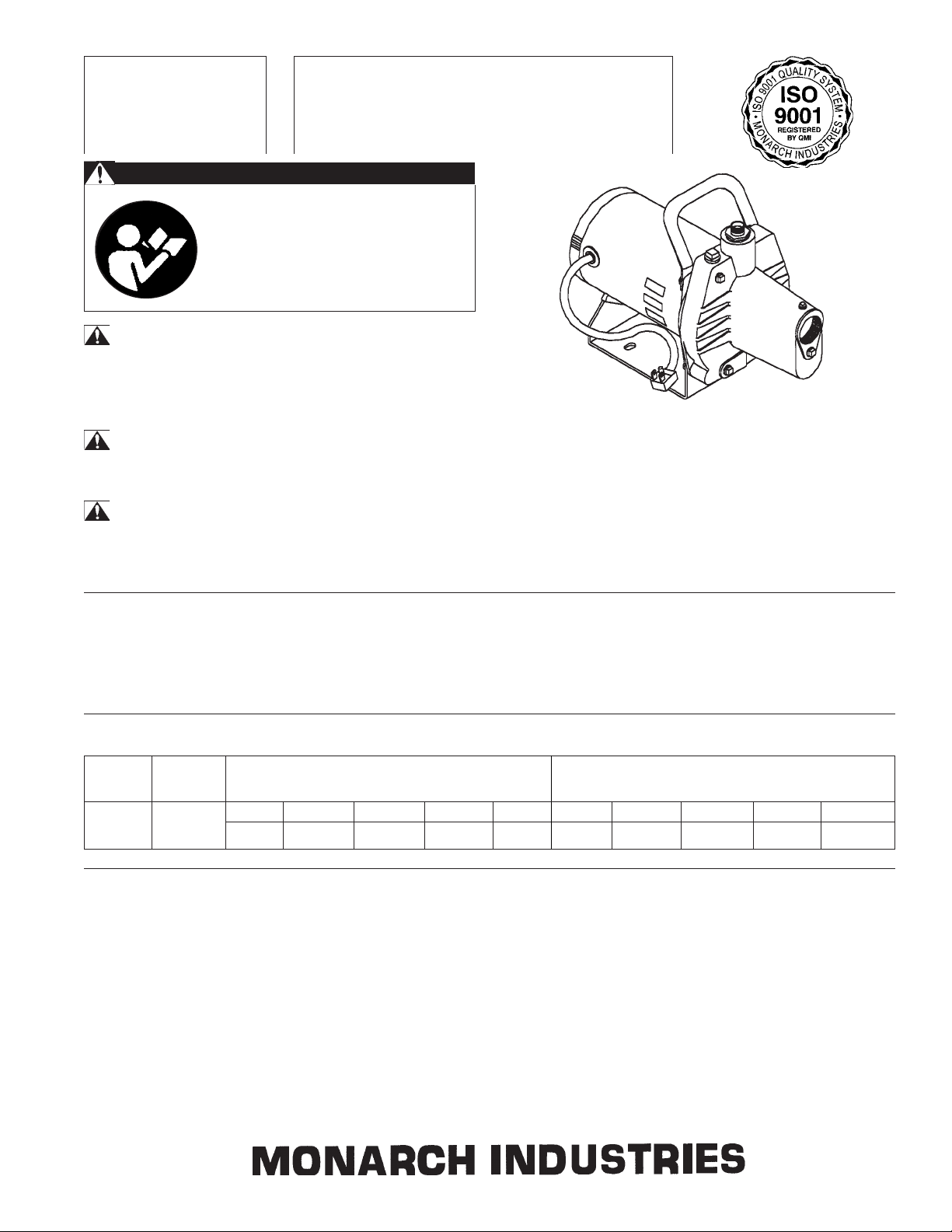
c) Replacing Mechanical Seal: (See Fig. 2)
Disassembly
1) Shut off the power to the pump at the main sevice panel.
2) Open a tap in the water system to release the pressure.
3) Remove the drain (12) and prime plugs to allow the pump to
drain.
4) Remove the 4 bolts (1) and remove casing (2).
5) Pry the diffuser (4) out of the casing using 2 slotted screwdriv-
ers for leverage.
6) Remove cap (5) and insert a screwdriver to prevent the shaft
from turning while unscrewing the impeller (6)(GE m o -
tors). For A.O. Smith motors, remove rear cover and hold the
shaft using a flat wrench inserted from the side, through the
opening in the end of the housing. If the impeller cannot be
turned by hand, insert a flat object into the impeller vane.
7) Slip the rotating seal (7) off the shaft and remove the seal plate
(8).
8) Remove the ceramic seal seat (9) from the seal plate. Fig.2
Reassembly
1) Clean all the parts thoroughly before assembling.
2) Push ceramic seal (9) it into the seal plate using thumbs only.
Make sure the smooth surface of the ceramic seat faces
outwards.
3) Put the seal plate back on the motor.
4) Slip on rotating seal (7) to the shaft with the 'carbon' ring
towards the ceramic seat.
5) Replace the impeller (6) and the diffuser (4).
6) Replace the casing (2) making sure that the venturi is properly
seated, and that the gasket is not damaged and is in place.
7) Reinstall the drain plugs.
8) Reconnect the power.
9) Prime pump, start, check for leaks.
a) Priming: Do not run the pump before priming it, since the seal and impeller
could be permanently damaged. Remove the plug from the street tee and
pour clean water into the unit until casing and suction line are completely
filled. Replace the priming plug and start the motor. If the unit is properly
primed, it should pump almost immediately. If not, repeat the priming
procedure until all the air has been eliminated from the suction line. If an
in-line check valve is used in place of a foot valve, the initial priming time
may take 5 to 15 minutes depending on the suction lift, (higher suction lift
requires longer priming times). At 10 feet or greater suction lifts, water
should be added to the casing approximately every 3 min-
utes until primed. If the pump does not prime within 25
minutes, stop the pump and check for suction leaks.
b) Draining: Should the unit be subject to freezing, it will be
necessary to drain the pump and tank. To do this, shut off the
power to the pump at the main electrical service panel. Open
a valve in the system to release the pressure. Remove drain
and priming plugs from the casing. Allow ample time for
system to drain before reinstalling the plugs!

LIMITED MONARCH INDUSTRIES WARRANTY
For one year from date of purchase, Monarch Industries will replace or repair for the original purchaser, free of
charge, any part or parts, found upon examination by any Monarch Industries Authorized Service Depot or by the
Monarch factory, to be defective in material or workmanship or both. Equipment and accessories not manufac-
tured by Monarch Industries are warranted only to the extent of the original manufacturer's warranty. All transpor-
tation charges on parts submitted for replacement or repair under this warranty must be borne by the purchaser.
For warranty service see your nearest Monarch Industries Authorized Service Depot. THERE IS NO OTHER
EXPRESS WARRANTY. IMPLIED WARRANTIES INCLUDING THOSE OF MERCHANTABILITY AND
FITNESS FOR A PARTICULAR PURPOSE ARE LIMITED TO ONE YEAR FROM PURCHASE AND TO
THE EXTENT PERMITTED BY LAW. LIABILITY FOR CONSEQUENTIAL DAMAGES UNDER ANY AND
ALL WARRANTIES ARE EXCLUDED TO THE EXTENT EXCLUSION IS PERMITTED BY LAW.
This warranty is an addition to any statutory warranty.
TROUBLES SHOOTING GUIDE
a) Motor will not start:
1) No power due to blown fuses, open switches or loose connec-
tions.
b) Pump fails to deliver water:
1) Pump not completely primed.
2) Suction lift is too great.
3) Foot valve is either not submerged, buried in the mud or
plugged.
c) Pump losses prime:
1) Air leaks in suction line.
2) Well draw down too far.
3) Faulty foot valve.
d) Pump delivers water but not at rated capacity:
1) Leaks in suction or discharge line.
2) Foot valve, suction line, impeller or nozzle are partially
plugged.
3) Suction lift is greater than recommended.
4) Improper impeller rotation or low speed.
5) Motor does not come off starting windings.
6) Low line voltage at motor.
1-800-PUMPBIZ
PumpBiz.com
Other Monarch Industries Water Pump manuals
Popular Water Pump manuals by other brands

Westward
Westward 5NUD9 Operating instructions and parts manual

Himel
Himel HAV SP Series user manual

Eagle
Eagle A100 Installation, operation and maintenance instructions

Alentec & Orion
Alentec & Orion 22440 user manual

hecht
hecht 3301 Original instructions

Grundfos
Grundfos PS.R.05-17 Installation and operating instructions

Espa
Espa TIPER instruction manual

Wilo
Wilo HiSewlift 3 Series Installation and operating instructions

Pentair
Pentair NOCCHI VSD manual

Larzep
Larzep HEP0020 INSTRUCTIONS & MAINTENANCE SHEET

Nippon Oil Pump
Nippon Oil Pump Cyclone Filter Pump User instruction manual

Debem
Debem IM 80 Instructions for use and maintenance