Money Controls ARDAC WACS-2 Guide

Specification and Adjustment Manual
World Acceptor Cassette System
ARDAC Brand WACS-2
ARDAC-2 Protocol
Money Controls Manual Part Number 44x477
Rev. 8
BANKNOTE ACCEPTORS IN MANY COUNTRIES AROUND THE WORLD

ARDACWACS-2 Specification and Adjustment Manual
44X477 Rev. 8
05/16/03 0-1
Specification and Adjustment Manual
World Acceptor Cassette System
WACS-2
ARDAC-2
Manual Part Number 44x477 Rev. 8.
--- May 1, 1997 Initial Release
A –August 6, 1997 Added Spare Part Recommendations to Diagrams Section, new cleaning information,
EPROM changing instructions, key lock installation, and other content improvements.
Standardized text and layout of all manuals covering similar equipment.
B –Sept. 16, 1997 Text and illustration revisions, expansions, and additions per Service and Software
Engineering Departments.
C –August 25, 1998 Text and illustration revisions, per Service Department.
D –Nov. 2, 1998 Added Data Grabbing Addendum, EPROM specs and Burn-in Instructions, new stacker
text, and made miscellaneous changes and corrections throughout.
E –Dec. 8, 1998 Revised Section 4, Diagnostics to reflect cumulative upgrades in Host and Diagnostic
Software.
F –Jan 3, 1999 Revised calibration procedure to reflect latest revision.
G –Nov. 19, 1999 Revised Diagnostic (Bench) mode instructions to reflect latest revision.
8. –May 16, 2003 Added references for Smart Cassette and Docking Station. Updated host simulator
instructions. Added DB-9 references and general updates. Converted from revision
letters to revision numbers to accommodate Money Controls part number system.

ARDACWACS-2 Specification and Adjustment Manual
44X477 Rev. 8
05/16/03 0-2
Copyright © 2003 by Money Controls Inc.
This document is protected by the copyright laws of the United States of America and other countries.
This document may not, in whole or in part, be copied or converted to any mechanical, electronic, or machine-
readable form without consent of Money Controls, Inc. Exception is made for authorized distributors or agents of
Money Controls, Inc. who may make copies as needed to support sales efforts or end users of this equipment.
Money Controls, Inc. reserves the right to revise the product or contents of this manual at any time without notice or
obligation.
No warranty is expressed or implied concerning use of this documentation or associated hardware and
software. In no event will Money Controls, Inc. be liable for any associated costs, losses, or damages incurred
through their use, even if advised of such possibility. Any risks are assumed completely by the user.
This document contains company-confidential, proprietary information, which may not be disclosed to unauthorized
parties without consent of Money Controls, Inc.
Money Controls, Inc.
34099 Melinz Parkway
Eastlake, Ohio USA 44095
Phone: (440) 946-3000 Fax: (440) 946-9832
CONVENTIONS USED IN THIS MANUAL
In this manual, certain information will be set off from the main text for special consideration:
NOTE
A NOTE identifies additional information or instructions, which may help, clarify an operation or procedure.
CAUTION
A CAUTION identifies additional information or instructions, which should be followed to avoid damage to the
equipment. WARNING
A WARNINGidentifies safety-related information or instructions, which should be followed to avoid personal
injury.

ARDACWACS-2 Specification and Adjustment Manual
44X477 Rev. 8
05/16/03 0-3
0. Table of Contents
0. TABLE OF CONTENTS................................................................................................................................................0-3
1. DESCRIPTION AND SPECIFICATIONS...............................................................................................................1-1
SYSTEM DESCRIPTION –WORLDACCEPTOR CASSETTE SYSTEM 2 (WACS-2)..............................................................1-1
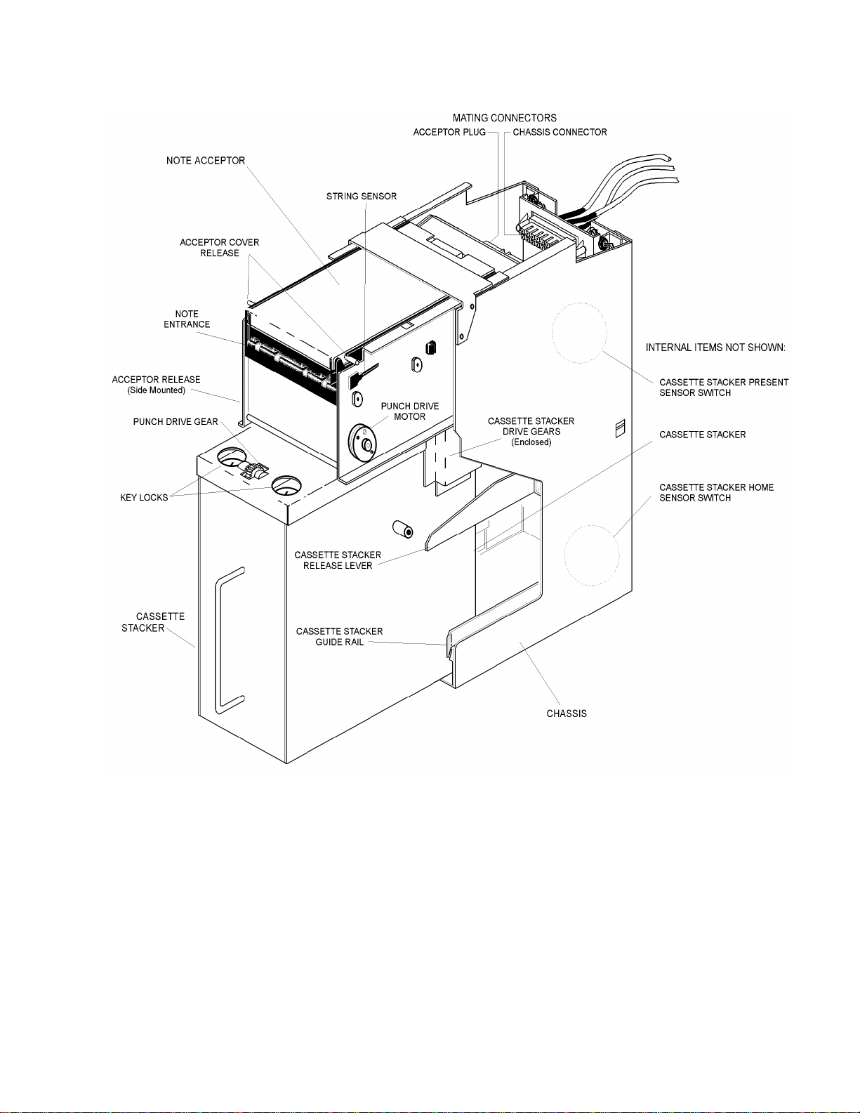
TERMINOLOGY...........................................................................................................................................................................1-3
MAIN SUBASSEMBLY PART NUMBERS...................................................................................................................................1-4
CHASSIS MOUNTING RECOMMENDATIONS...........................................................................................................................1-5
FEATURES...................................................................................................................................................................................1-5
SPECIFICATIONS.........................................................................................................................................................................1-7
CONNECTOR DESCRIPTION....................................................................................................................................................1-10
CONNECTOR SPECIFICATIONS...............................................................................................................................................1-10
MAIN CHASSIS CONNECTOR TO SYSTEM..............................................................................................................1-11
HOST INTERFACE CONNECTIONS..........................................................................................................................................1-12
DIP SWITCH SETTINGS AND FUNCTIONS.............................................................................................................................1-13
2. HOST MACHINE INSTALLATION.........................................................................................................................2-1
HOST INSTALLATION & SETUP................................................................................................................................................2-1
INSTALLATION OVERVIEW.......................................................................................................................................................2-1
POWER SUPPLY AND VOLTAGE REQUIREMENTS..................................................................................................................2-2
CONNECTION OF THE WACS-2 SYSTEM TO THE HOST.......................................................................................................2-2
INSTALL NEW OR UP-GRADED EPROM / FLASH ON MICROPROCESSOR BOARD (OPTIONAL)..................................2-2
PROGRAMMING NEW FIRMWARE INTO AN EPROM / FLASH..........................................................................................2-3
EPROM / FLASH REMOVAL AND REPLACEMENT.............................................................................................................2-3
CHECK THE DIP SWITCH SETTINGS AND RE-SET AS REQUIRED........................................................................................2-4
INSERT STACKER MODULE INTO THE CHASSIS.....................................................................................................................2-4
INSERT NOTE ACCEPTOR MODULE.........................................................................................................................................2-4
SYSTEM POWER-UP...................................................................................................................................................................2-6
3. SYSTEM OPERATION.................................................................................................................................................3-1
FUNCTIONAL DESCRIPTION OF SYSTEM MODULES..............................................................................................................3-1
NOTE ACCEPTOR:................................................................................................................................................................3-1
CASSETTE STACKER:.........................................................................................................................................................3-1
CHASSIS:..................................................................................................................................................................................3-1
OPERATIONAL NOTES -ACCEPTOR........................................................................................................................................3-3
REMOVAL OF THE NOTE ACCEPTOR.......................................................................................................................................3-4
OPERATIONAL NOTES -CASSETTE STACKER........................................................................................................................3-4
REMOVAL OF THE CASSETTE STACKER.................................................................................................................................3-4
OPERATIONAL NOTES -CHASSIS............................................................................................................................................3-7
OPERATIONAL NOTES -SYSTEM POWER-UP SEQUENCE.....................................................................................................3-7
4. SYSTEM DIAGNOSTICS.............................................................................................................................................4-1
INTRODUCTION..........................................................................................................................................................................4-1
EQUIPMENT AND SOFTWARE REQUIRED FOR ARDAC-2 HOST SIMULATOR..................................................................4-1
ARDAC-2 SIMULATOR CONNECTIONS.................................................................................................................................4-2
HOST SOFTWARE INSTALLATION............................................................................................................................................4-2
RUNNING THE HOST SOFTWARE.............................................................................................................................................4-3
HOST SOFTWARE MAIN SCREEN DISPLAY............................................................................................................................4-4
ARDAC-2 HOST SIMULATOR SET-UP...................................................................................................................................4-8
DIAGNOSTIC (BENCH) MODE..................................................................................................................................................4-8

ARDACWACS-2 Specification and Adjustment Manual
44X477 Rev. 8
05/16/03 0-4
DIAGNOSTIC (BENCH) MODE OPERATIONS..........................................................................................................................4-9
DUAL DENSITY CALIBRATION..............................................................................................................................................4-14
5. MAINTENANCE..............................................................................................................................................................5-1
INTRODUCTION..........................................................................................................................................................................5-1
ADJUSTMENTS...........................................................................................................................................................................5-1
CALIBRATION CARD.................................................................................................................................................................5-1
CLEANING...................................................................................................................................................................................5-2
CLEANING INSTRUCTIONS........................................................................................................................................................5-3
USING A CLEANING CARD.......................................................................................................................................................5-4
6. ARDAC-2 & DIAGNOSTIC INTERFACE..............................................................................................................6-1
INTRODUCTION..........................................................................................................................................................................6-1
DESCRIPTION..............................................................................................................................................................................6-1
COMMUNICATIONS PARAMETERS...........................................................................................................................................6-2
BENCH MODE USING DIAGNOSTIC CONNECTOR..................................................................................................................6-3
BENCH MODE OPERATIONS USING SETUP MODE.................................................................................................................6-3
7. RECOMMENDED SPARE PARTS AND DIAGRAMS.......................................................................................7-1
INTRODUCTION..........................................................................................................................................................................7-1
SERVICE AND REPLACEMENT PARTS MANUAL....................................................................................................................7-1
SPARE PARTS RECOMMENDATION..........................................................................................................................................7-1
BOARD LOCATIONS...................................................................................................................................................................7-1
8. GATHERING NOTE DATA USING THE WACS-2 SYSTEM.........................................................................8-1
INTRODUCTION..........................................................................................................................................................................8-1
HOW TO GATHER DATA...........................................................................................................................................................8-2
9. CASSETTE DOCKING STATION SYSTEM.........................................................................................................9-1
TABLE OF CONTENTS........................................................................................................................................................9-1
INTRODUCTION..........................................................................................................................................................................9-1
CASSETTE DOCKING STATION SYSTEM COMPONENTS........................................................................................................9-1
DOCKING STATION SOFTWARE...............................................................................................................................................9-2
REPLACEMENT OF MICROPROCESSOR EPROM...................................................................................................................9-3
INSTALLATION CONNECTIONS.................................................................................................................................................9-4
INSTALLATION OF DOCKING STATION HOST SOFTWARE....................................................................................................9-4
INITIAL SET-UP: THE CHASSIS NUMBER TO GAME ID MAP..............................................................................................9-5
DOCKING STATION SYSTEM HOST COMPUTER-NORMAL OPERATION (HOST.EXE)...................................................9-7
DOCKING STATION(S) -NORMAL OPERATION.....................................................................................................................9-8
MICRO SOFT EXCEL MACRO...................................................................................................................................................9-9

ARDACWACS-2 Specification and Adjustment Manual
44X477 Rev. 8
05/16/03 1-1
1
1. Description and Specifications
System Description –World Acceptor Cassette System 2 (WACS-2)
The Money Controls World Acceptor Cassette System 2 (ARDAC WACS-2) identifies, collects, and stacks
paper currency or the equivalent into a secure, lockable, removable cassette stacker. The WACS-2 is a
modular system consisting of a note acceptor, cassette stacker, and mounting chassis. These three modules
and other system components are identified and illustrated in Figure 1-1.
The WACS-2 offers world capability and can be used for any country or currency set within the
dimensional limits detailed in the Specifications in this chapter. Changing acceptance from one country or
currency set to another is easily accomplished by updating the acceptor’s EPROM / FLASH. The acceptor
resident firmware determines system operating features and the bank notes accepted. Refer to Table 1-1 for
firmware and bank note acceptance information.
Section 3, System Operation describes the functions and operations of the major System components.
This system can be ordered with a “Smart Cassette” option, which allows the cash box to record data about
the quantity and denomination of notes accepted. This smart option also has an electronic serial number
stored in the chassis that can be used to track where a cash box has been installed.
The smart system records the following information in the cassette:
1. Chassis Serial Number
2. Number of each denomination accepted
3. Reject Count for notes not recognized
4. Note Handling Reject Count
5. Tamper Count
6. Acceptor Jam Count
7. Time since memory last cleared

ARDACWACS-2 Specification and Adjustment Manual
44X477 Rev. 8
05/16/03 1-2
Figure 1-1
WACS-2 System Components

ARDACWACS-2 Specification and Adjustment Manual
44X477 Rev. 8
05/16/03 1-3
Terminology
For convenience and clarity several terms are used interchangeably throughout this manual. These and other system
terms and components are illustrated in Figure 1-1.
-The terms Money Controls World Acceptor Cassette System 2, ARDAC WACS-2 and System describe the
complete system, which includes all three modules (note acceptor, cassette stacker, and chassis).
-The chassis is the rectangular frame mounted permanently in the host equipment. The chassis secures the
acceptor and stacker in precise alignment in the host. Smart cassette models contain a read only memory to
store and communicate its specific chassis ID number. The stacker home sensor and system wiring harness
are chassis components.
-The terms imbedded note acceptor, note acceptor and acceptor describe only the portion of the System,
which actively transports and identifies the notes.
-The terms cassette, cassette stacker, cassette, and stacker refer to the removable, lockable box located in the
bottom section of the system chassis. It contains the memory device to store acceptor data.
-The terms note, bank note, and bill refer to paper currency or equivalent, which is inserted into the note
acceptor and stored in the stacker.
-The terms “Smart Cassette System”, “Smart System” and “Smart Cash box” refer to an option that can be
installed on new systems ordered that allow tracking of system data in a memory button located on the cash
box.

ARDACWACS-2 Specification and Adjustment Manual
44X477 Rev. 8
05/16/03 1-4
Main Subassembly Part Numbers
The part numbers for the ARDAC WACS-2 main modules are listed below. Figure 1-1 illustrates these
modules and various other subassemblies of the System. Refer to Section 8, Diagrams and Parts Listings
for more details parts information.
13 volt units TYPE ACCEPTOR PART
NUMBER STACKER
PART NUMBER
CHASSIS
PART NUMBER
77X16 Standard (83mm)
88 x 3329 48 x 827 2 x 6629
77X25 Current Loop 88 x 3316 48 x 827 2 x 6236-3
77X27 USA 88 x 3330 48 x 827 2 x 6629
77X38 Smart 88 x 3329 48 x 833 2 x 6818
77X40 85 mm 88 x 3331 48 x 834 2 x 6852
12-24 volt units TYPE ACCEPTOR PART
NUMBER STACKER
PART NUMBER
CHASSIS
PART NUMBER
77X24 USA 88 x 3328 48 x 827 2 x 6629
77X32 Standard (83mm)
88 x 3327 48 x 827 2 x 6629
77X35 Smart 88 x 3327 48 x 833 2 x 6818
77X36 Current Loop 88 x 3337 48 x 827 2 x 6629
77X41-341 USA-MM 88 x 3328 48 x 827 2 x 7016
STACKER PART
NUMBER TYPE DESCRIPTION
48X827 Non-Smart Metal
48X833 Smart Metal
48X834 Non-Smart 85mm
Metal
48X843 Smart 85mm Metal
48X862 Non-Smart Plastic
48X863 Smart Plastic

ARDACWACS-2 Specification and Adjustment Manual
44X477 Rev. 8
05/16/03 1-5
Chassis Mounting Recommendations
The chassis must be supported from underneath and be bolted to the host housing. The Dimension Drawing (Figure 1-3)shows
the location of the chassis mounting hardware (notes 1 through 4).
As a minimum, secure the chassis to the host housing by doing the following:
a. Boltone side and the bottom of the chassis to the housing.
b. Bolt one side and the back of the chassis to the housing. (Although the chassis must be supported from underneath, it is
not necessary to bolt the bottom if the back is bolted to the host housing.)
c. Bolt both sides of the chassis to the housing. (Bottom support is not required.)
Features
The Money Controls World Acceptor Cassette System 2 (WACS-2) has a number of features which minimize the need
for maintenance, and simplify installation and operation:
-MODULAR DESIGN: The acceptor and cassette stacker are easily removed from the chassis. The acceptor provides
all mechanical drive for itself and the cassette stacker. This simplified design makes the cassette stacker useful as an
exchangeable, lockablecashbox.
-FIRMWARE-CONTROLLED OPERATING SYSTEM: A microprocessor located in the acceptor controls: note
identification,notehandling, stacking, and communicationwiththe host. Output signalsindicatenote denomination
and acceptor status. Two drive motors in the acceptor drive the acceptor and the cassette stacker components.
-LOCKABLE CASSETTE STACKER: The cassette stacker contains locations for two independent key locks for
maximum security.
-STABLE, RELIABLE OPERATION: Note recognition devicesareself-compensating and require no adjustments or
maintenance. Systems are ready for immediate installation.
-12-24VDC OPERATION: The ARDAC WACS-2 System operates from a single, regulated DC source, which must be
suppliedbythehostsystem.
-EASY ACCESS TO THE NOTE PATH FOR MAINTENANCE: The acceptor opens to fully expose the sensors and
note transport mechanism. This facilitates inspection, cleaning, and servicing.
-SOLID CONSTRUCTION: Structural components of the acceptor, cassette stacker, and mounting chassis are of
welded steel construction for durability, strength, and security.
-STRING DETECTOR: This security system provides maximum protection against all types of stringing and numerous
other intrusive cheating devices.
-Optional Smart Cassette data tracking system allows user to download data detailing the amount of money and the
quantity of notes directly from the cash box without the need to unlock and open it.

ARDACWACS-2 Specification and Adjustment Manual
44X477 Rev. 8
05/16/03 1-6
Figure 1-2
Phantom view: Top, Front, and Sides

ARDACWACS-2 Specification and Adjustment Manual
44X477 Rev. 8
05/16/03 1-7
Specifications
NOTE SIZE RANGE: 62mm x 120mm to 83mm x 172mm
ACCEPTANCE RATE: 95% or better on first insertion with street-gradenotes.
STACKER CAPACITY: 500 notes, minimum, in street-gradecondition.
STACKER LOCKS: Dual locks, 0.625" to 1.125" barrel length
POWER SUPPLY: External to WACS-2
Mounting Requirements: Separate from System chassis
Supply Voltage (Max): 12 Volts to 24 Volts DC
Max Current (Refer to Chart 1-1)
POWER SUPPLY CONNECTOR: 2-pin Molex Connector 35x552-2 with crimp terminals 35x435.
Mating connector: 35x436-2 with 35x434 crimp terminals
POWER CONSUMPTION: 6 VA Idle, 48 VA maximum (With 12V input)
STATUSMONITOR: Status is monitored through ARDAC-2serialprotocol
HOST COMMUNICATION: ARDAC-2 Serial Protocol (RS-232)
HOST INTERFACE CONNECTOR: DB-25 Female (Can plug directly to P.C. serial port)
DB-9 Female (MMG Units) (Can plug directly to P.C. serial port)
SYSTEM DIMENSIONS: (Standard 83mm system)
Acceptor: 3.520"H x 4.210"W x 9.000"L
Stacker: 8.042"H x 3.476"W x 7.940"L
Overall: 12.442"H x 4.558"W x 7.100"L
Mounting Arrangements: Refer to Figure 1-3.
OPERATING ENVIRONMENT: 0° To 45° C, 15% To 90% Relative Humidity.
Optional smart cassette system: Will record data for up to 4 separate chassis in separate records in cash
box memory button. Cash box data can be read and cleared either by
using an optional docking station or through a bench type computer
connection.

ARDACWACS-2 Specification and Adjustment Manual
44X477 Rev. 8
05/16/03 1-8
Input Volts VS Input Current
0
0.5
1
1.5
2
2.5
3
3.5
4
12 13 14 15 16 17 18 19 20 21 22 23 24
Input Voltage
Input Current (Amps)
Input Volts VS Input Current
Chart 1-1
The use of WACS2 with a 12VDC–24VDC supply board operating at
12VDC can create a hazardous condition. This is only when operating at
12VDC. It is recommended that Fused Harness Assembly 2X7171 is used
for 12VDC applications. Units operating at 24VDC are not affected.
The following WACS2 Systems/Acceptors are affected:
System # Acceptor #
77x24 88x3328
77x32 88x3327
77x35 88x3327
77x36 88x3337
77x41 88x3328
77x41-341 88x3328

ARDACWACS-2 Specification and Adjustment Manual
44X477 Rev. 8
05/16/03 1-9
Figure 1-3
Dimension Drawing (Standard 83mm Note Path System)

ARDACWACS-2 Specification and Adjustment Manual
44X477 Rev. 8
05/16/03 1-10
Connector Description
Refer to Figure 1-4. Power and I/O connections to the system electronics are made through the main system
internal wiring harness (not shown) to a single connector located at the top rear of the chassis. The acceptor
unit makes or breaks all connections when the acceptor is installed or removed from the chassis. The
external wiring harness is permanently mounted to the chassis connector, and provides cabling and
termination for the power supply, and Host I/O or Money Controls Host Simulator connections.
Connector Specifications
Figure 1-5 shows the pin-outs of the main chassis to note acceptor connections. These connectors appear as
viewed from the rear of the acceptor and the rear of the Main Chassis Connector.
Figures 1-5 through 1-8 show the pin-outs of the external harness connectors:
-The 2-pin power supply connector connects the WACS-2 to the host or bench power supply.
-The DB-25-pin (DB-9 Optional) host I/O connector passes control signals between the Host and WACS-2.
Figure 1-4
Diagnostic Bench Interface

ARDACWACS-2 Specification and Adjustment Manual
44X477 Rev. 8
05/16/03 1-11
MAIN CHASSIS CONNECTOR TO SYSTEM
WIRING HARNESS
PIN # FUNCTION HARNESS COLOR
1
2
3Stacker Present White / Red
4
5
6RS-232 RX Violet
7Ground Green
8Memory Button (Smart Only) Blue (Smart only)
8Ground (Non-Smart only) Green (Non-Smart only)
9RS-232 TX Yellow
10 Stacker Home Orange
11 +12 to 24V White / Orange
12 Ground Green
13
14
Figure 1-5
14 Pin Rear Connector

ARDACWACS-2 Specification and Adjustment Manual
44X477 Rev. 8
05/16/03 1-12
2-PIN POWER CONNECTOR (12-24VDC)
PIN # FUNCTION HARNESS COLOR
1+12 to 24VDC White / Orange
2Ground Green
Money Controls Part Numbers: 35x592 housing with 35x593 pins
Figure 1-6
Two pin Power Connector
Host Interface Connections
The DB-25 connector is used for communication with the host machine and can also be connected to a P.C. so that
the acceptor can be run with a Host Simulator program. This also allows access to diagnostics.
DB-25 HOST CONNECTOR
PIN # FUNCTION HARNESS COLOR
1----- -----
2WACS Receive Data Violet
3WACS Transmit Data Yellow
4----- -----
5Ground on DB-9-----
6----- -----
7Ground on DB-35 Green
8-25 ----- -----
Figure 1-7
DB-25 Host Interface
(DB-9 Optional)

ARDACWACS-2 Specification and Adjustment Manual
44X477 Rev. 8
05/16/03 1-13
Figure 1-8
WACS-2
Diagnostic Interface
DIP Switch Settings and Functions
The microprocessor board used in the System note acceptor has 1bank of eight DIPswitches. These switches set the
System’s operating mode and enable or inhibit acceptance of certain notes. For the location of these DIPswitches,
refer to Figure below. Table 1-1 describes the DIPswitch functions. DIPswitch settings may vary from table 1-1
depending on specific firmware version installed in machine.
Figure 1-9
Dip Switch Location on Micro board

ARDACWACS-2 Specification and Adjustment Manual
44X477 Rev. 8
05/16/03 1-14
SWITCH BANK 1 SWITCH OFF (Enable) SWITCH ON (Inhibit)
SWITCH 1-1NOTE 1 ACCEPT NOTE 1 INHIBIT NOTE 1
SWITCH 1-2NOTE 2 ACCEPT NOTE 2 INHIBIT NOTE 2
SWITCH 1-3NOTE 3 ACCEPT NOTE 3 INHIBIT NOTE 3
SWITCH 1-4NOTE 4 ACCEPT NOTE 4 INHIBIT NOTE 4
SWITCH 1-5NOTE 5 ACCEPT NOTE 5 INHIBIT NOTE 5
SWITCH 1-6NOTE 6 ACCEPT NOTE 6 INHIBIT NOTE 6
SWITCH 1-7Firmware Dependant Firmware Dependant Firmware Dependant
SWITCH 1-8Firmware Dependant Firmware Dependant Firmware Dependant
ARDAC2 Serial Protocol CREDIT / VEND / ACCEPT / INHIBIT CODES
Credit 1 = a Credit 2 = b Credit 3 = c Credit 4 = d Credit 5 = e Credit 6 = f Credit 7 = g Credit 8 = h
Vend 1 = i Vend 2 = j Vend 3 = k Vend 4 = l Vend 5 = m Vend 6 = n Vend 7 = o Vend 8 = p
Accept 1 = I Accept 2 =J Accept 3 = K Accept 4 = L Accept 5 = M
Accept 6 = N Accept 7 = O
Accept 8 = P
Inhibit 1 = A Inhibit 2 = B Inhibit 3 = C Inhibit 4 = D Inhibit 5 = E Inhibit 6 = F Inhibit 7 = G
Inhibit 8 = H
ARGENTINA 2510 20 50 100
AUSTRALIA 510 20 50 100
BARBADOS 2510 20
BRAZIL 1510 50 100 220
BULGARIA 2510 20 50
CANADA 510 20 50 100
CHILE 500 1000 2000 5000 10,000 20,000
CHINA 12510 50 100 20
COLOMBIA 2000 5000 10,000 20,000 50,000 1000
CYPRUS 1510
CZECH
REPUBLIC 20 50 100 200 500 1000
DENMARK 50 100 200 500 1000
EASTERN
CARIBBEAN 510 20 50
ENGLAND-SCOTLAND 510 20 50
ESTONIA 10 25 50 100 500
EURO 510 20 50 100 200 500
EURO / ENG-
SCOT 5 POUND 10 POUND 20 POUND 50 POUND 5 EURO 10 EURO 20 EURO 50 EURO
EURO /
DENMARK 50 KRONER
100 KRONER
200 KRONER
500 KRONER
5 EURO 10 EURO 20 EURO 50 EURO
EURO /
NORWAY 50 KRONER
100 KRONER
200 KRONER
500 KRONER
5 EURO 10 EURO 20 EURO 50 EURO
EURO /
SWEDEN 20 KRONER
50 KRONER
100 KRONER
500 KRONER
5 EURO 10 EURO 20 EURO 50 EURO
HONG KONG -Type 1 20 100
HONG KONG
-Type 2 20 100
HONG KONG
-Type 3 10 20 50 100 500 1000
HUNGARY 500 1000 2000 5000 10,000
ICELAND 500 1000 2000 5000
INDIA 10 50 100 500
ISRAEL 20 50 100 200
JAPAN 1000 2000 5000 10000
KENYA 100 200 500 1000
KOREA 1000 5000 10000
MALAWI 50 100 200 500
MALAYSIA 12510 50 100 500
MEXICO 10 20 50 100 200 500

ARDACWACS-2 Specification and Adjustment Manual
44X477 Rev. 8
05/16/03 1-15
NEW
ZEALAND 510 20 50 100
NORWAY 50 100 200 500
POLAND 10 20 50 100 200
RUSSIA 10 50 100 500 1000
SAUDI
ARABIA 510 20 50 100 200
SINGAPORE 2510 50
SLOVENIA 1000 5000 10,000
SOUTH
AFRICA 10 20 50 100 200
SRI-LANKA 10 20 50 100 200 500 1000
SWEDEN 20 50 100 500
SWITZERLAND
10 20 50 100 200
TAIWAN 100
TURKEY 50,000 100,000 250,000 500,000 1,000,000
U.A.E. 510 50 100 200 500
U.S.A. with $2
12510 20 50 100
U.S.A. w/o $2
1510 20 50 100
UGANDA 5,000 10,000
VENEZUELA 1000 2000 5000 10,000 20,000
ZIMBABWE 100
Table of contents
Other Money Controls Banknote Counter manuals