Dors 820 User manual

820
v.1.2, 2019
Banknote counter
820
Service maintenance manual

Service maintenance manual
820
2
Contents
INTRODUCTION .................................................................................................................................................5
1SAFETY INSTRUCTIONS..........................................................................................................................6
2GETTING STARTED ..................................................................................................................................7
3GENERAL DESCRIPTION.........................................................................................................................9
4PRODUCT APPEARANCE AND OPERATION CONTROLS.............................................................10
5SPECIFICATIONS AND SET CONTENT ..............................................................................................13
5.1 SPECIFICATIONS.....................................................................................................................................13
5.2 SUPPLIED CONTENTS..............................................................................................................................14
6PREVENTIVE MAINTENANCE .............................................................................................................15
7MAINTENANCE ........................................................................................................................................29
7.1 OVERVIEW.............................................................................................................................................29
7.2 RECOMMENDED TOOLS AND CONSUMABLES..........................................................................................29
8PRODUCTS DISASSEMBLY AND ASSEMBLY...................................................................................30
8.1 REMOVAL AND INSTALLATION OF BANKNOTE GUIDES...........................................................................30
8.2 REMOVAL AND INSTALLATION OF SIDE COVERS ....................................................................................30
8.3 REMOVAL AND INSTALLATION OF REAR COVER.....................................................................................38
8.4 WIRE DRESSING.....................................................................................................................................39
8.5 REMOVAL AND INSTALLATION OF DRIVERS MODULE ............................................................................46
8.6 REMOVAL AND INSTALLATION OF HOPPER UNIT ....................................................................................54
8.7 REMOVAL AND INSTALLATION OF EXTERNAL INTERFACES MODULE.....................................................57
8.8 REMOVAL AND INSTALLATION OF PSU..................................................................................................59
8.9 REMOVING AND INSTALLING BVS ADAPTER MODULE...........................................................................62
8.10 REMOVING AND INSTALLING BVS MODULE ..........................................................................................69
8.11 REMOVING AND INSTALLING RJ45 CONNECTOR AND ETHERNET CABLE................................................73
8.12 REMOVING AND INSTALLING RASPBERRY PI MODULE...........................................................................75
8.13 REMOVING AND INSTALLING THE MODULES OF OPTICAL INTERRUPTER.................................................78
8.14 REMOVAL AND INSTALLATION OF REDIRECTOR SENSOR MODULE..........................................................82
8.15 REMOVAL AND INSTALLATION OF CABLES OF REDIRECTOR AND OPTICAL INTERRUPTER MODULES......84
8.16 REMOVAL AND INSTALLATION OF HOPPER MOTOR MODULE..................................................................86
8.17 REMOVAL AND INSTALLATION OF MAIN MOTOR MODULE......................................................................98
8.18 REMOVAL AND INSTALLATION OF WHEELS..........................................................................................102
8.19 REMOVAL AND INSTALLATION OF REJECT POCKET ..............................................................................116
8.20 REMOVAL AND INSTALLATION OF REDIRECTOR AND SOLENOID...........................................................118
8.21 REMOVAL AND INSTALLATION OF GEARS ON SHAFTS OF FEEDING AND DISPENSING ROLLERS .............120
8.22 REMOVING AND INSTALLING CIS FRAME ASSEMBLY...........................................................................122
8.23 REMOVING AND INSTALLING THE REAR FRAME ASSEMBLY..................................................................125
8.24 REMOVAL AND INSTALLATION OF TOP COVER UNIT ASSEMBLY...........................................................126
8.25 REMOVAL AND INSTALLATION OF DISPENSING ROLLERS SHAFT ASSEMBLY.........................................127

Service maintenance manual
820
3
8.26 REMOVAL AND INSTALLATION OF HOOKS............................................................................................128
8.27 REMOVAL AND INSTALLATION OF SEPARATOR COVER ASSEMBLY.......................................................130
8.28 REMOVAL AND INSTALLATION OF SEPARATOR BRACKET ASSEMBLY...................................................133
8.29 REMOVAL AND INSTALLATION OF FEEDING WHEELS SHAFT ASSEMBLY...............................................137
8.30 REMOVAL AND INSTALLATION OF DAMPER SPRINGS............................................................................141
8.31 REMOVAL AND INSTALLATION OF TOP.................................................................................................142
8.32 REMOVAL AND INSTALLATION OF LOWER ENVELOPE ASSEMBLY.........................................................143
8.33 REMOVAL AND INSTALLATION OF STACKER UNIT ASSEMBLY ..............................................................144
8.34 REMOVAL AND INSTALLATION OF OPENING SENSOR MODULE..............................................................147
8.35 REMOVAL AND INSTALLATION OF STACKER SHAFT ASSEMBLY............................................................148
8.36 REMOVAL AND INSTALLATION OF DRIVE ROLLERS SHAFTS..................................................................149
8.37 REMOVAL AND INSTALLATION OF REJECT POCKET ENVELOPE .............................................................152
8.38 REMOVAL AND INSTALLATION OF PRESSING SHAFT UNIT ....................................................................154
8.39 REMOVING AND INSTALLING PU ROLLERS SHAFT................................................................................156
8.40 REMOVING AND INSTALLING PU ROLLERS SHAFT (NO.2) ...................................................................158
8.41 REMOVAL AND INSTALLATION OF UPPER ENVELOPE ASSEMBLY..........................................................160
8.42 DISASSEMBLY AND ASSEMBLY OF HOPPER UNIT..................................................................................163
8.43 DISASSEMBLY AND ASSEMBLY OF TOP COVER UNIT ASSEMBLY...........................................................174
8.44 DISASSEMBLY AND ASSEMBLY OF REJECT POCKET ASSY .....................................................................178
8.45 DISASSEMBLY AND ASSEMBLY OF SEPARATOR COVER UNIT ................................................................184
8.46 DISASSEMBLY AND ASSEMBLY OF SEPARATOR BRACKET ASSY............................................................186
8.47 DISASSEMBLY AND ASSEMBLY OF STACKER UNIT................................................................................193
8.48 DISASSEMBLY AND ASSEMBLY OF PSU ...............................................................................................199
8.49 DISMANTLING AND ASSEMBLING OF CIS FRAME ASSY ........................................................................205
8.50 DISASSEMBLY AND ASSEMBLY OF REAR FRAME ASSY .........................................................................211
8.51 DISASSEMBLY AND ASSEMBLY OF STACKER SHAFT .............................................................................228
8.52 ASSEMBLY AND DISASSEMBLY OF LOWER ENVELOPE IN AN ASSEMBLY...............................................232
8.53 DISASSEMBLY AND ASSEMBLY OF UPPER ENVELOPE............................................................................238
8.54 REPLACEMENT OF DISPENSING ROLLER GLIDES ...................................................................................240
8.55 DISASSEMBLY AND ASSEMBLY OF RIGHT WALL UNIT...........................................................................241
8.56 DISASSEMBLY AND ASSEMBLY OF LEFT WALL UNIT.............................................................................250
9PRODUCT ADJUSTMENT.....................................................................................................................254
9.1 ADJUSTMENT OF MISALIGNMENT OF SEPARATOR BRACKET UNIT.........................................................254
9.2 ADJUSTMENT OF MAGNET SENSORS POSITION......................................................................................257
9.3 FUNCTIONAL TESTING OF MAGNET SENSORS........................................................................................271
9.4 MAGNET SENSORS INTRINSIC NOISE TEST ............................................................................................274
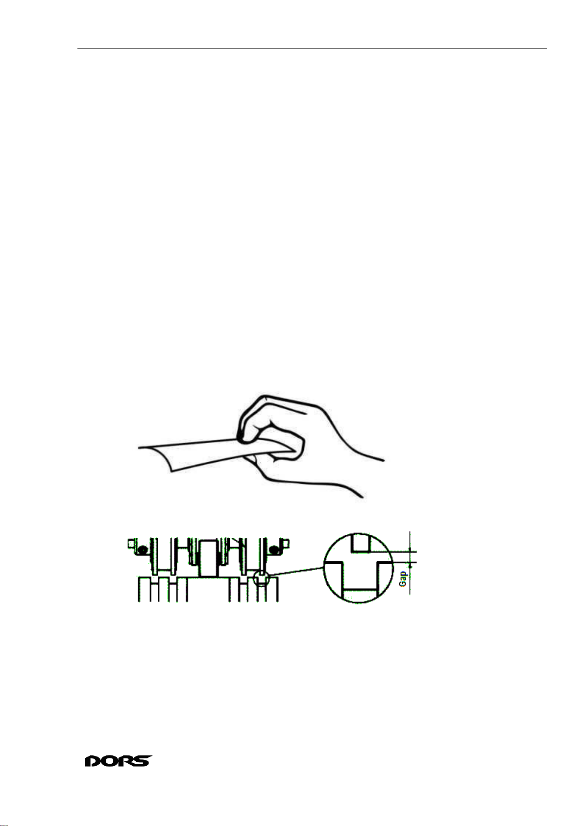
9.5 ADJUSTMENT OF THE GAP BETWEEN THE ROLLERS ..............................................................................277
9.6 REDIRECTOR ADJUSTMENT ..................................................................................................................278
9.7 LOWER ENVELOPE ASSEMBLY POSITION ADJUSTMENT.........................................................................283
9.8 OPENING SENSOR MODULE POSITION ADJUSTMENT..............................................................................286

Service maintenance manual
820
4
9.9 UPPER ENVELOPE POSITION CONTROL AND ADJUSTMENT ....................................................................289
9.10 SEPARATOR ROLLERS POSITION ADJUSTING.........................................................................................295
9.11 SETTING DATE AND TIME OF THE RTC MODULE ..................................................................................298
10 ENGINEERING TESTING .....................................................................................................................302
10.1 SERVICE MODE ....................................................................................................................................302
10.2 ERROR MESSAGES................................................................................................................................316
10.3 COUNTER FIRMWARE UPDATING..........................................................................................................319
10.4 COUNTER CALIBRATION ......................................................................................................................324
10.5 CALIBRATION CONTROL ......................................................................................................................332
10.6 TOUCHSCREEN CALIBRATION ..............................................................................................................333
10.7 EEPROM CLEARING ...........................................................................................................................338
10.8 TROUBLESHOOTING ALGORITHMS .......................................................................................................340
10.9 COUNTER FIRMWARE RECOVERY.........................................................................................................371
10.10 REGISTRATION OF NEW BVS MODULE AFTER REPLACEMENT..............................................................374
10.11 BVS REPOSITORY RESET......................................................................................................................375
10.12 CONNECTING EXTERNAL DEVICES ......................................................................................................377
11 DORS 820 DOCUMENTATION.............................................................................................................378
11.1 DORS 820 LIST OF CABLES..................................................................................................................378

Service maintenance manual
820
5
Introduction
This manual is a reference guide for the staff performing maintenance and repair of
DORS 820 banknote counter (hereinafter product or counter).
Following all the instructions in this manual ensures maximum security for the mainte-
nance staff, proper maintenance and repair of the equipment.
Read this manual carefully before getting started.
Please follow the required steps and their sequence exactly for each operation at
testing, maintenance and commissioning.

Service maintenance manual
820
6
1Safety instructions
Operations may be performed by certified personnel that got through instructions on la-
bor safety when operating electrical appliances and is qualified not lower than 1st qualifying
group for operation of electrical installations up to 1000 V.
Warning: Don’t wear long jewelry or garments (e.g. necktie or loose coat) that can
get into the moving parts of the product during testing operations. Long hair needs to be
put up.
Warning: to avoid electric shock or personal injury, follow these precautions:
1.1. Don’t touch the powered on counter by wet hands or other body parts.
1.2. Power the counter from AC mains outlet with protective earth contact (PE) only.
AC mains outlet must be available from the user desk.
1.3. Do not use power cord other than supplied with the counter, do not pull the pow-
er cord to unplug it from the outlet, do not bend, do not squeeze or twist the power cord.
1.4. When closing the top cover please mind your fingers for not to be pinched.
When operating with the top cover opened ensure it is fixed properly. Sudden cover closing
may cause injury.
1.5. Avoid penetration of liquids or foreign objects into the product.
1.6. Mechanical impact on the counter’s casing is prohibited.
1.7. Keep your hands and other body parts away from moving parts of the product.
1.8. Unplug the counter from the mains after work.
1.9. Turn off the power switch if the counter is supposed not to be used for a long
time.
1.10. The counter must be installed on flat horizontal surface
1.11. To avoid counter damage do not switch the counter off, do not unplug it from the
mains and do not open the top cover during operation.
1.12. Before cleaning the tract sensors ensure the counter is unplugged from the mains
1.13. When installing and operating the counter please provide enough space for open-
ing of the top and for access to the tract.
1.14. Do not install the counter where it can be exposed to soot or steam to avoid short
circuit or fire.
1.15. It is not recommended to use the counter at extremely low or high temperatures,
high humidity or dustiness and expose it to the direct sunlight.

Service maintenance manual
820
7
2Getting started
2.1. Find a place to operate the counter. Ensure the surface is flat and not exposed to
direct sunlight, there is no dust, dirt, steam or smoke, and there is no strong vibration. The mains
outlet should be near the product and easy to access. The place chosen in accordance with these
requirements will ensure proper counter operation and avoid damage to its parts and compo-
nents.
2.2. Ensure the AC mains voltage corresponds to rated voltage value of the counter.
2.3. If counter has been in the cold for a long time, keep it at room temperature for two
hours before switching the power on.
2.4. Ensure all the precautions specified in the relevant section of this manual are met.
2.5. Before operation install the supplied banknote guides on the counter –see “Opera-
tion manual”, sub-section “Preparing for Operation”.
2.6. Adjust the gap of banknote feeding device. The manufacturer presets the required
gap taking into account peculiarities of the currency to be counted. However, if the counter often
rejects valid banknotes and the reject report shows the reason “small interval in the tract”, “small
interval in the slider”, “long”, “twoness”, it is required to rotate the screw 1 (see Fig. 1) clock-
wise (“-” to decrease the gap). If the reject report shows “angle error”, “dimensions”, it is re-
quired to slightly rotate the screw 1 (see Fig. 1) counterclockwise (“+” to increase the gap).
Use a good quality banknote (not a decrepit one). Take is as shown below:
Turn the rollers as shown below. There should be no cogs where the banknote will pass:
Insert the banknote short edge between the rollers as shown below:

Service maintenance manual
820
8
The gap between separating and feed rollers should be adjusted so that one banknote
would pass between the rollers with little friction. If the banknote passes loosely, reduce
the gap. If the banknote can hardly be inserted, increase the gap.
2.7. Connect the counter with the supplied power cord to the mains outlet.
2.8. Adjust the banknote guides to the length of the longest banknote in the package to
be counted.

Service maintenance manual
820
9
3General description
DORS 820 counter is designed for counting and sorting banknotes of Russian rubles,
Ukrainian hryvna, Kazakhstan tenge, US dollars, Euros, Great Britain pounds, PRC renminbi
and other currency (depending on complete set) determining their authenticity, par value and
amount. Authenticity is determined by comparing 9 machine-readable features with reference
data stored in the counter’s memory. The counter has an oprtion of banknote serial number de-
tection and comparison and an option of banknote fitness detection. The counter is equipped with
USB 2.0 type B slot and can be connected to a PC.

Service maintenance manual
820
10
4Product appearance and operation controls
Appearance of the product is shown in figures 1, 2, 3.
Fig. 1
Fig. 2
Fig. 3
1. Gap adjustment screw
2. Banknotes guides
3. Hopper
4. Top hold buttons
5. Control panel
6. Reject pocket
7. Stacker
8. Stacker wheels
9. Handles for counter carrying
10. Top
11. Bottom
12. Power supply switch
13. Safety fuse
14. Power cord slot
15. Slot for connection of external printer or CCTV
16. USB slot for connection to a PC
17. Remote display slot
18 Cover
19 Ethernet connector (for DORS 820E)
20 HDMI connector (for DORS 820Rs)
21 USB connectors (for DORS 820Rs)

Service maintenance manual
820
11
Control panel
Functional keys
1(MIX)key / count mode indicators (serial
number detection, fitness, ATM - off) / Ether-
net connection (red - off; green-blue / green-
grey flashing –exchange data with the serv-
er);
2Count rate key
3Banknote orientation sorting key
4Batch mode key (inactive in MIX mode)
5Currency select key
6Send count results to the printer key
7Count reset key
8“REPORT” submenu key
9ADD mode on/off key
10 Auto / manual start key
11 UV detection, Magnet detection, optical densi-
ty and strict test on/off key
12 Settings menu key
13 Selected currency indicator / Currency select
key
14 Counted banknotes quantity
15 Rejected banknotes quantity
16 Counted sum
17 System time
For detailed information about keys operation refer to “DORS 820 Operation manual”.
1Start / User Select touch keys
2Main operation modes keys
3Colour LCD touchscreen

Service maintenance manual
820
12
Operation procedure
For detailed information on operation procedure refer to “DORS 820 Operation manual”
If an error appears, please check the section “10.2 Error messages”.
Note:
Prepare the banknotes to be counted as shown in Fig. 4,
and remove broken, wet, greasy and dirty banknotes.
Separate banknotes should not protrude from the stack.
Fig. 4

Service maintenance manual
820
13
5Specifications and set content
5.1 Specifications
Hopper capacity1, max
500 banknotes
Stacker capacity, max
200 banknotes
Reject pocket capacity, max
100 banknotes
Banknotes counting speed (±10%)
600/900 (800)/1200/1500 banknotes per minute
Banknote size
100—190 mm (width), 58—90 mm (length), 0,05—
0,2 mm (thickness)
Quantity of banknotes in the batch
1—999
Banknotes feeder
roller, friction-type
Sensors
A bar of sensitive elements, a built-in banknote identi-
fication system and verification of authenticity fea-
tures.
Two contact image sensors, with a resolution of 200
dpi, with illumination in the translusive infrared radia-
tion, and translusive and reflected light, an integrated
system for determining currency and denomination, as
well as checking for signs of authenticity. 370nm UV
light check sensors: beam-through: 2 pcs, reflection 2
pcs. Banknote magnet properties detection sensor:
multichannel, inductive, with central and side bank-
note area control.
Display
TFT LCD, 480x272, High Colour (64K), 4.3”, with
resistive touchscreen
Power supply
AC 100-240 V, 50/60 Hz
Current consumption, max
2А (100 V); 1А (240 V)
Operating temperature range
10 to 35 °С
Relative humidity at 25°С
40…80%
Atmospheric pressure
84 to 107 KPa (630 to 820 mm Hg)
Dimensions (max):
Height
Width
Depth
345 mm
305 mm
295 mm
Net weight, max
10 kg
Gross weight, max
13 kg
1Hereinafter the capacity (for hopper, accepting and reject pockets) is shown for new banknotes. Pockets
capacity depends on banknote’s extent of wear, thus it is not recommended to use maximum values of pockets ca-
pacity for worn out and decrepit banknotes.

Service maintenance manual
820
14
5.2 Supplied contents
5.2.1 Complete set includes:
DORS 820 banknote counter
power cord
stylus (2 pcs)
banknote guides (2 pcs)
USB cable (A-B type)
Operation manual
brush
wiping cloth
calibration cards set
packing

Service maintenance manual
820
15
6Preventive maintenance
The further specified maintenance is required to perform once in a quarter at normal op-
eration conditions:
ambient temperature 15 to 35 ºС;
relative humidity 40 to 80 %;
atmospheric pressure 84 to 107 KPa (630 to 820 mm Hg).
If the counter is operated more intensively (more than 8 hours per day), the maintenance
specified is to be carried out more often.
1 - Unplug the power cord from the mains outlet.
2 - Take off side covers (see s. 8.2 Removal and installation of side covers)
3 - Take off rear cover if required (see s. 8.3 Removal and installation of rear cover)
4 - Disconnect power cable (red-white-black-yellow) from X4 connector @ Drivers
module (see Fig. 79). If the length of the cable lets putting the PSU near the counter, then the
cable may be remained in the connector.
5 - Remove PSU (refer to s. 8.8 Removal and installation of PSU). To do this release
power cable from the cable ties if required (Fig. 55, Fig. 61) or remove the ties (Fig. 64).
6 - Using vacuum cleaner remove the dust from the hopper, the stacker and reject
pocket, from tract envelopes, PSU, bottom and counter mechanisms (see Fig. 5 Fig. 8 Fig. 9
Fig. 10 Fig. 11 Fig. 13, Fig. 17).
7 - Using compressed air and soft brush remove dust from LEDs and sensors of the
hopper, stacker and reject pocket, from tract envelopes, scanning bar and lighting bar, magnet
sensors, pulse sensor wheels, pulse sensors, redirector sensor, opening sensor (see Fig. 5 Fig. 8
Fig. 9 Fig. 10 Fig. 11 Fig. 13 Fig. 15 Fig. 16 Fig. 18 Fig. 19 Fig. 20 Fig. 21).
8 - If necessary (visible dirt), using lint free cloth moistened with alcohol clean the
scanning bars and the mirror, counting sensors, reflection UV-sensors and control panel (see
Fig. 5 Fig. 8 Fig. 13 Fig. 15 Fig. 16).
9 - Using lint free cloth moistened with cleaning and restoration agent for rubber
surfaces wipe all the rollers and rollers’ glides (see Fig. 6 Fig. 7 Fig. 8 Fig. 12 Fig. 13 Fig. 14
Fig. 15 Fig. 16).
10 -Disconnect magnet sensor cables, disconnect 14-pin cable (BVS-CMB_X4) from
combined sensor module, 8-pin cable (Light-ADPT) from lighting module and CIS cable (Fig.
22).
11 -Take out the screws of combined sensor module, take out the module with UV
sensor frames (Fig. 23, Fig. 24).
12 - Teke out the screws of the lighting module, take out the module (Fig. 25 Fig.
26).
13 -Clean the inner surface of the frame with vacuum cleaner, compressed air and/or
soft brush; clean semi-transparent lens of the frame and UV-sensors protection glass thorough-
ly (clean with the tissue moistened with alcohol), see Fig. 27.

Service maintenance manual
820
16
14 - Clean the lighting module, combined sensor module and UV sensor frames with
vacuum cleaner, compressed air and/or soft brush (Fig. 24 Fig. 26).
15 -Remove the metal bar to clean the rollers if required (Fig. 28 Fig. 29).
16 -Take out the springs and the roller’s axle (Fig. 29 Fig. 30).
17 -Clean the area around magnet sensors with vacuum cleaner, compressed air
and/or soft brush (Fig. 30).
18 -Wipe the rollers with lint-free cloth moistened with rubber restoration liquid (Fig.
29).
Fig. 5
Remove
dust
Wipe

Service maintenance manual
820
17
Fig. 6
Fig. 7
Wipe rollers
Wipe rollers

Service maintenance manual
820
18
Fig. 8
Fig. 9
Wipe rollers
Remove
dust
Remove
dust

Service maintenance manual
820
19
Fig. 10
Fig. 11
Remove
dust
Remove
dust

Service maintenance manual
820
20
Fig. 12
Fig. 13
Wipe
rollers
Remove
dust
Wipe
rollers
Wipe
rollers
Other manuals for 820
1
Table of contents
Other Dors Banknote Counter manuals