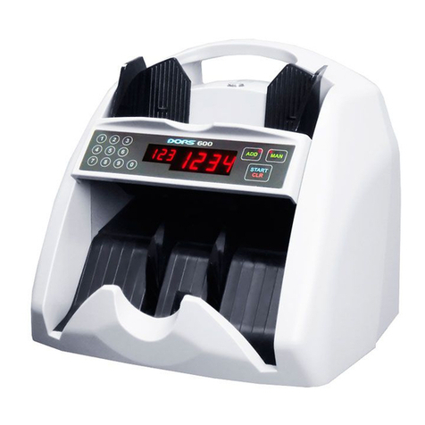
Dors 600 User manual

www.dors.com
USER MANUAL
BANKNOTE COUNTER
© , 2009KB DORS LLC
User Manual
Version .33

BANKNOTE COUNTER DORS 600 3
CAREFULLY READ THIS MANUAL
BEFORE OPERATION START !S
CONTENTS
.......... ..................................................4
Specifications....… .........................................…......
Safety Precautions....... .........................………...................….......
Delivery Set..................................... ...............................…….…...
Appearance............................ .........................….................…......
Operating keys............. ........………………......................…..........
..... .... ...... ....................................................
Error Codes............................. ...........................…......................1
Maintenance ................... ............................................1
Transportation and Storage........... .................................………...1
Troubleshooting.......................... ..........................………………..1
................................ 5
.......... 6
.......... 6
......... 7
.......... 8
Operation . ................ .......... 10
......... 1
................ .......... 4
......... 4
......... 4
Brief Information or Customerf .....

BANKNOTE COUNTER DORS 600
4
This manual supplies you with information you may require for installation,
operation and maintenance of the (thereafter –
'counter'). Following safety precautions and observing operating conditions, you
provide a reliable and long life operation of the counter
Banknote counter DORS 600
BRIEF INFORMATION FOR CUSTOMER
Banknote Counter DORS 600 developed in Russia by KB DORS LLC.
Assembled in China by DORS Industries (China) Ltd., No 17, Shilong information
industrial park, Shilong town, Dongguan city, Guangdong.
Service term years*.is 7
* Under condition that detector is being used in strict accordance with this user manual and applied
technical standards.
5
SPECIFICATIONS
Hopper capacity, not more than 0 used banknotes
Stacker capacity, not more than 100 used banknotes
Banknote counting speed (±10%) 1200 banknotes per minute
Banknotes feed system roller system of a friction type
Counting sensor an extra-sensitive element,
a built-in system of automatic comparison with the ROM data
Display a red light LED display
Overall dimensions (width x depth x height), not exceeding 260x230x250 mm
Net weight, not more than kg
Gross weight, not more than 5 kg
Power supply 220VAC ±10%, 50 Hz
Operating temperature range +10°C to +35°C
Air relative humidity at the air temperature of + 25°C 40% to 80%
Atmospheric pressure 84 to 107 kPa (630 to 800 mm Hg)
Power consumption, not more than W
Banknote size..................... ..100 mm (width), 50– mm (length),
0.05–0.2 mm (thickness)
Batch select –999
..............................................40
.............................................
...............................
............................................
.........................................................
...............................................................................
.......
............................................................................5.3
........................................................................6.
.......................................................................
.......................................................
............................
.......................................
...............................................................40
................ –165 85
................................................................................................1
BANKNOTE COUNTER DORS 600
Design and specifications are subject to change without notice in order to improve the quality of
device.
6BANKNOTE COUNTER DORS 600
SAFETY PRECAUTIONS
To ensure long life and reliable operation of the counter, user should meet the
following operation requirements and observe below-mentioned safety
precautions :
1. Avoid getting any metal object or liquid into the counter.
2. Use power outlet with protective earth contact (PE) to connect the counter to
power supply.
3. Unplug the counter after work completion.
4. If the counter is not in use for a long time, its power switch should be in the OFF
position.
5. The device should be installed on a flat horizontal surface; do not use the
counter at extreme low or high temperatures; avoid humidity and exposition to
the direct sunlight.
6. Do not touch the parts inside the counter, if it is connected to power supply.
7. When installing the counter, mind that a high content of dust in the room may
decrease its operation quality.
8. To avoid any fire or short circuit, do not install the device in places where it may
be at risk of soot or steam.
DELIVERY SET
A delivery set includes the following:
Counter 1 pc.
Power cord 1 pc.
manual 1 pc.
Package 1 set.
.........................................................................................................
...................................................................................................
User .................................................................................................
.......................................................................................................
1
2
3
4
5
67
8
Banknote guide
Hopper
Control panel
Displays
Stacke
Screw for thickness adjustment of
the counted banknotes
Power switch
Power connector
s
r
APPEARANCE
1
8
4
2
3
7
5
6
6
Fig. 1. Appearance
7
BANKNOTE COUNTER DORS 600

8BANKNOTE COUNTER DORS 600
CLR
START
ADD MAN
123
456
7890
5
Fig. 2. Control panel
OPERATING KEYS
1
1
Batch keys
Setting the number of banknotes in a batch:
«A »
To reset the batch size «0»
You can set the batch size from 1 to 999 banknotes. When setted number of
notes is counted, the device stops, indicates the total number of the counted
banknotes and makes an audio signal. The stacker capacity is 100 banknotes;
therefore, counting stops as soon as it is full. To continue counting, remove the
banknotes from the stacker, and counter continues operation automatically.
1. Use the keys (see Fig. 2) to set the required number of banknotes in a
batch. The display shows the setted batch size. The counter is ready to
count.
2. When counted number of banknotes is less than the set one, you hear an
audio signal, the display shows the actual number of the banknotes and a
three-digit display shows an message. In this case, add banknotes
into the hopper.
, press the key until the data of a three-digit display
are cleared.
dd
14
1
2
3
4
5
6
7
8
Batch keys
Three-digit display (indicate present
set of batch)
Four-digit display (indicate number
of counted notes)
ADD key (addition mode)
START/CLR keys (start/clear)
MAN key (switch between manual
and automatic mode)
Indicator of manual mode
Indicator of addition mode
236
7
8
BANKNOTE COUNTER DORS 600 9
To switch on/off sound signal 0
ADD key (addition mode):
START/CLR keys (start/clear)
MAN key (switch between manual and automatic mode)
MAN
MAN
START/CLR
MAN
, press button within 3 seconds. When sound
mode is on, the message « » appears on indicator. Turn off position
will be shown as « ».
1. When addition mode is activated, the indicator on the control panel (see
Fig. 2) is red.
2. In addition mode the number of just counted banknotes is added to the
number counted earlier.
1. The key switches the counter in the manual or automatic modes.
2. Press the key to activate a manual mode. The indicator on the
control panel (see Fig. 2) gets red, it means that the manual mode is
activated. To start counting, press the key.
3. Press the key to switch off the manual mode. The indicator is fade.
The counter starts counting automatically, when banknotes are placed into
the hopper.
4
8
5
6
7
7
The first function of key is to start counting when a manual mode
is switched on (the indicator in the upper corner of the key is flashing).
When the banknotes are placed into the hopper and the key is
pressed, the counting starts.
The second function of key is to clear the counting results (if there
had been no message).
START/CLR
MAN
START/CLR
START/CLR
ERROR

10 BANKNOTE COUNTER DORS 600
OPERATION
To ensure the operation of the counter is correct, the following actions should be
performed:
1. Switch on the counter, a self-testing process activates. Make sure that the
stacker's wheels and the feeder's rollers are rotate during self-test and the
figures « » appear on the counting and batch displays. As soon as self-test is
over, the « » appears on a four-digit display. The device is ready for counting
banknotes.
2. Adjust a feeder's clearance to achieve the required thickness of banknotes.
Set the clearance between the separating rollers and the feeding ones, using
the adjustment screw (see Fig. 1). The clearance should let one banknote
pass freely between the rollers but prevent two stuck banknotes from passing
between them. Turning the screw in a clockwise direction provides increasing
of clearance, a counterclockwise turning decreases the clearance.
3. Use the operating keys (Table 1 shows their purposes) to set the required
operation.
Operating Keys.
6
Table 1.
_-
_-
Select required size of batch
Purpose
Clear the counting display
Activate addition mode
Set the manual start or the automatic one
Start counting in a manual mode
Press the key
«ADD»
1….0
«»MAN
«START/CLR»
«START/CLR»
4. The counter starts operating automatically after the banknotes have been
placed into the hopper. If the counter is in the manual mode, press the
key to start the opera
tion.
START/CLR -
5. In case of an error, follow the
recommendation of the
section to eliminate it.
Prepare the banknotes to be counted as shown in Fig. 3; remove the torn, wet,
grease or dirty ones, as well as the banknotes of other denominations.
«ERROR
CODES»
Notes:
Fig 3.
ERROR CODES
In the case of error, the counter stops automatically, makes an audio signal
and ERROR CODE appears on the display. See table 2 “Error codes…” to
determine the cause of error and the method for its elimination. Sometimes if a
problems emerges, no error code is displayed. In this case refer to table 3
“Troubleshooting” to determine the method of problem's elimination.
Table 2. Error Codes Displayed When the Counter is Switched On
Counting sensor error.
Right sensor.
Left sensor.
Switch the counter off.
Consult the service division.
ERROR CODE CAUSE OPERATOR ACTIONS’S
Counting sensor error or
drive motor error.
Switch the counter off.
Consult the service division.
There were banknotes in
the hopper at the moment
of energizing the device
OR malfunction of hopper's
sensor.
Remove the banknotes from
the hopper. Remove any
foreign objects from the
hopper.
There were banknotes in
the stacker at the moment
of energizing the device
OR malfunction of
stacker's sensor.
Remove the banknotes from
the stacker. Remove any
foreign objects out of the
stacker.
BANKNOTE COUNTER DORS 600 11
Processor board error. Switch the counter off.
Consult the service division.
Switch the counter off.
Consult the service division.
Processor board error.

BANKNOTE COUNTER DORS 600
12
A foreign object blocks one
of the counting sensors at
the start counting.
Switch the counter off.
Remove the foreign object
from the path. Switch the
counter on.
The banknotes are
jammed inside the device.
The counter is unable to
continue counting.
Switch the counter off.
Eliminate the jammed
banknotes carefully in a
manual way, avoid any
banknote damage. Switch
the counter on.
Table 2a. Error Codes Displayed When the Counter is Switched On
ERROR CODE CAUSE OPERATOR ACTIONS’S
A continuous chain: the
banknotes cannot be
separated for correct
counting.
Remove the banknotes that
got stuck together.Adjust the
clearance of the feeder for
operation with thinner
banknotes. Turn the screw
clockwise to get the proper
clearance.
Remove the banknote from
the stacker. Adjust the
clearance of the feeder for
operation with thinner
banknotes. Turn the screw
clockwise to get the proper
clearance.
There is detected a doubled
banknote or a very dark
one.
A banknote length is
different from the length of
the previous ones by more
than 10%.
Remove the banknote with a
non-standard length.
The banknotes get jammed
in the hopper; the counter
cannot load the banknotes
from the hopper.
Adjust the banknote guides.
If required, adjust the
clearance of the feeder as
described above.
ERROR CODE CAUSE OPERATOR ACTIONS’S
A banknote skewness
exceeds 22.5° degrees.
The banknotes should be set
neatly in the hopper. Adjust
the banknote guides.
There are no banknotes in
the hopper when the
counter operates in a
manual start mode.
Add some banknotes into the
hopper. The counter
continues counting after the
key has been
pressed.
START/CLR
Maintenance is required. Switch the counter off.
Consult the service division.
There is discovered a very
transparent banknote. Remove the banknote.
There is detected a folded
banknote or a damaged
one.
Remove the banknote.
There were banknotes in
the stacker when the device
counted a batch in the
manual mode.
Remove the banknote from
the stacker. The counter
continues counting after the
START/CLR key has been
pressed.
BANKNOTE COUNTER DORS 600 13
*«»Digit 87 is given as an example. Real digits may differ from given.
The number of counted
banknotes in the stacker is
less than required number
of notes in the batch.
Place additional banknotes
into the hopper and continue
counting.
Quantity of banknotes
laying in stacker.*
9999 banknotes were
calculated This number is
maximum that subject to
displayed.
.Remove banknotes from
stacker and hopper, then
press START/CLR key.
Notes:
For removing ERROR message just delete banknotes from the stacker. Counter
will continue to work automatically.

Table 3. Troubleshooting
TROUBLESHOOTING
MAINTENANCE
The counter should be stored in the manufacturer's package in a heated and
ventilated storage room, at the temperature of +5°C to +40°C and a relative
humidity not exceeding 80%.
The counter should be transported in the manufacturer's package by an
automobile or railway transportation (in a covered transport vehicle), by air
transportation in the pressurized modules at the temperature of °C to +50°C,
a relative humidity of the air up to 98%, at the temperature of +25°C and the air
pressure 84 to 107 kPa (630 to 800 mm Hg).
–35
TRANSPORTATION AND STORAGE
FAILURE ELIMINATION METHOD
Make sure that the counter is connected to the
power supply and the power cord is plugged
into the connector on the counter back cover.
If these terms are observed but the counter
fails to switch on, consult the service division.
Counter fails to switch on.
Switch the counter off. Consult the service
division.
The display shows the message
not indicated in Tables 2 and 2a
after the device is switched on
or during its operation.
BANKNOTE COUNTER DORS 600
14
The preventive maintenance includes a partial disassembling of the counter
by a service engineer. The counter required the maintenance every 90 days. If the
counter works more than one shift a day), the above-mentioned maintenance
should perform more frequently
1. Switch off the banknote counter if it is not used.
2. Wipe the external parts of the counter with a dry clean lint-free tissue.
.
On a daily basis:
Switch the counter off. Consult the service
division.
There is a loud buzz sound or
another unusual noise during
operation.
Other manuals for 600
1
Table of contents
Other Dors Banknote Counter manuals