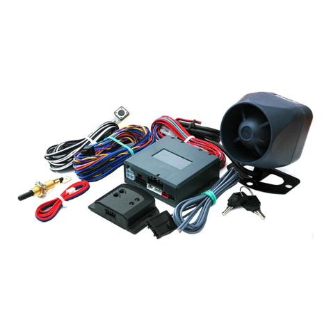
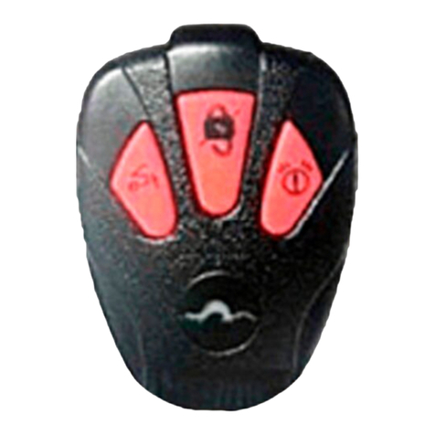
Mongoose SG-1100 User manual

MONGOOSE
Wireless Burglar
Alarm
System
Model SG
-
1100
Included parts;
1 x SolarGuard Console
–
SG01
2 x Remote Controls
–
RM03
1 x PIR Detector
_ IR02
1 x Magnetic Detector
–
MT01
1 x Lead Acid Batt
ery for Console
2 x 9v Alkaline Batteries for detectors
2 x 12v
23a
Batteries for remote Controls
1 x Console Mounting Template
This manual
Instruction Manual
Please read this manual prior to installation
INTRODUCTION
CONGRATULATIONS
in selecti
ng the SolarGuard Wireless Burglar Alarm
System. The SolarGuard console and wireless detectors provide an extremely easy
installation and are amazingly simple to operate.
The SolarGuard is solar powered with power maintained by an internal sealed
Lead
-
aci
d rechargeable battery. The battery has life of approximately 3 years.
The standby current is incredibly small thus allowing the solar panel to maintain the
battery charge. In fact, the solar panel is so sensitive it will even top up the battery in
very c
loudy and overcast weather conditions, and even without top
-
up the system will
operate without light for up to 10 days.
The SolarGuard is fully protected by a tough Polycarbonate UV proof housing. All
electronic components are protected with moisture repe
llent materials applied during
manufacturing process to ensure long, reliable, trouble free operation. Two integral front
and rear tamper switches give maximum security to the unit. When activated, the
SolarGuard sounds a built
-
in twin siren system at a po
werful 115dBs and strobe will
flash. The siren duration is selectable from between 1 and 8 minutes. If it’s allowed to
sound for the full siren duration the strobe will latch and continue for approximately 20
minutes or until the system is disarmed.
The
SolarGuard can be set into any one of its active modes which includes Full Arm,
Disarm and Battery Change to allow for replacement of detector batteries without
triggering the tamper switches. The SolarGuard will provide audible chirps when
operated via th
e Remote Control but the option is included to select an silent LED light
indication instead which flashes behind the strobe lens of the SolarGuard and is fitted
as standard.
Individual zone setting in each detector allows you to customize the installatio
n with
Entry/Exit, Instant and 24H Zone selections. The Instant zone also provides an
Entry/Exit walk
-
through facility of 20 seconds, automatically allowing instant zone
“entry pass through”. This is particularly useful if you have to pass through an Insta
nt
zone to locate and operate the Remote Control when entering the property.
Please read this manual carefully to fully understand installation, setting up and
operation.
Mongoose (New Zealand) Limited
41A View Road, Glenfield, Auckland
Ph: (09) 443 3128
Fax: (09) 443 3129
Email:
sales@mongoose.co.nz
Website: www.mongoose.co.nz

OPERATING THE SYSTEM
FUNCTION
OPERATION
RESPONSE
ARM
Press ‘ Mode ’ button once
Function 1
: 1 beep + 1
LED flash
Function 2
: 1 LED flash
DISARM
Press ‘ Mode
’ button once
Function 1
: 3 beeps + 3
LED flashes
Function 2
: 3 LED flashes
PANIC
Press ‘ PANIC ’ button
Sirens sound immediately
and strobe flashes latched
for 20 minutes.
Press ‘Mode’ to cancel
ALARM MEMORY
If the alarm has been activated,
but is silent upon your return,
this system
warns of a possible
intrusion.
E
mit
s
beeps for 20 sec
’
s
and the LED will flash for 1
minute immediately after
d
isarming
the system.
To end
: Press ‘Mode’
DETECTOR LOW
B
ATTERY
The detector low battery
warning tone can be heard
when
you arm the system
E
mit
s
5 chirps and 5 LED
flashes instead of 1 chirp
to
confirm
arming but is a
warning of a low detector
battery.
Important note,
Please set
to Battery Change mode to
find o
ut
which
detector
has
a
low battery.
FUNCTION: See page
NOTE: If you arm, disarm and arm again too quickly, you will accidentally enter
‘test mode’
–
see below
TEST & BATTERY CHANGE MODE
A: Press ‘Mode’ once (arm)
–
1 chirp
B: Within 5 seconds press ‘Mo
de’ again (disarm)
–
3 chirps
C: Within 5 seconds press ‘Mode’ again
–
6 chirps, 6 LED flashes
-
confirms (test mode)
CONTENTS
ILLUSTRATION & DESCRIPTION
SOLARGUARD CONSOLE
PIR MOVEMENT DETECTOR
MAGNETIC TRANSMITTER
REMOTE CONTROLLER
PLAN
NING YOUR INSTALLATION
LOCATING THE SOLARGUARD CONSOLE
LOCATING THE WIRELESS PIR DETECTOR
LOCATING THE MAGNETIC TRANSMITTER
INSTALLATION EXAMPLE
PREPARING THE SYSTEM FOR INSTALLATION
SETTING THE MODE SWITCH
SETTING THE SITE CODE
SETTING SITE CODE ON
REMOTE CONTROLS
SETTING SITE CODE ON DETECTORS
SETTING SITE CODE ON SOLARGUARD CONSOLE
ZONE CODE
ACTIVE ZONES
SETTING UP OTHER FUNCTIONS
INSTALLING THE SYSTEM
INSTALLING THE SOLARGUARD CONSOLE
INSTALLING THE PIR DETECTORS
INSTALLING THE MAGNETIC TRAN
SMITTERS
INSTALLING THE REMOTE CONTROLS
SYSTEM TEST AFTER COMPLETING INSTALLATION
TESTING THE SOLARGUARD CONSOLE
TESTING THE PIR DETECTOR
TESTING THE MAGNETIC TRANSMITTER
OPERATING THE SYSTEM
CHANGING THE BATTERIES
MAINTENANCE
EXPANDING T
HE SYSTEM
YOUR QUESTIONS ANSWERED

ILLUSTRATION & DESCRIPTION
SOLARGUARD CONSOLE
1.
Solar panel
Takes energy during daylight hours to charge the internal battery
2.
Sirens
Two sirens sound in the event of activation
3.
Battery
High capacity 6
V/1.2Ah sealed Lead
-
acid rechargeable battery ensures
that siren & strobe is self maintainable during darkness and long winter period.
4.
Strobe board (optional)
High intensity Xenon strobe. When activated, it will latch
and continue for 20 minutes or u
ntil the system is disarmed.
5.
Siren duration selector
Selects siren duration from 1 minutes to 8 minutes
6.
Tamper switch
Switch that detects the opening of cover and removal of unit.
7.
Jamming selector
Select Jamming status. Switch ON by linki
ng the 2 pins on the
left (the factory default is OFF with the 2 right pins linked)
8.
LEARN button
Used to learn the frequency site code sent from the Transmitters
9.
Function switch
Allows you to disable the beep sounds when arming and
disarming t
he system. Function 1 has both audible (beeps) and visible (LED flash)
mode, and Function 2 has visible mode only.
10.
MODE switch
Must be set to
MODE
A
position.
11.
START button
Only used when power is first applied to the SolarGuard.
12.
DC jack
Used to quick charge the Lead
-
acid battery. If required, charge the
battery with a 12V/DC or AC adapter rated at 500mA min
–
not supplied
. (plug type
2.1 x 5.5mm)
PIR MOVEMENT DE
T
ECTOR
The detecting cover
age is 12 meters in a 120 degree arc on 3 layers when installed
at a height of 7 feet (2.1 meter) from floor.
Indicator
:
The red LED only operates when the PIR is set to the
‘
Test
’
mode.
MAGNETIC
DOOR /WINDOW
TRANSMITTER
(MDT)
Used to protect do
or or window causing activation when parted.
Indicator:
The red LED operates when the magnetic contacts are parted.
REMOTE CONTROLLER
(
2 supplied
)
‘MODE’
–
Used to ARM & DISARM the system
‘PANIC’
–
Instantly triggers the alarm in an
emergency

PLANNING YOUR INSTALLATION
Before proceeding with any part of the installation you must give very careful
consideratio
n to the location of detectors,
and the SolarGuard console.
It would prove extremely useful if you
sketch a plan of your
p
roperty and identify the
optimum location for each component of the system.
The above diagram shows the optimum positions for detectors, including those shown for
the shed and similar out buildings.
1.
SolarGuard siren/strobe unit
2.
PIR s
ensor(s)
3.
Magnetic trigger
(
s
)
LOCATING THE SOLARGUARD UNIT
The SolarGuard console should be mounted at least 1 meter below
a
gutter. This is
because in winter the sun is lower in the sky and you should avoid winter shadows where
possible.
Whilst the pane
l is manufactured with water repellents
–
it is not waterproof and should be
protected from heavy rain.
It is highly advisable that it should be mounted in a position to
shield it preferably under an overhanging roof line.
If water
-
blasting the house, do n
ot direct the water at this unit
–
protect it by using a
plastic bag or similar.
Avoid mounting the SolarGuard console on a completely shaded wall. Avoid shadows from
guttering roof overhangs, facia boards, neighboring walls, trees …etc.
The SolarGuard
console contains a receiver. However, reception of radio signals can be
affected by the presence of metallic objects within the vicinity of the SolarGuard console.
Therefore, it is important to mount the SolarGuard console a minimum distance of 1 meter
ra
dius away from any external and internal metalwork. i.e. external drainpipes, gutters and
internal radiators, mirrors etc.
The optimum transmitting range of your detectors is dependent on the location of your
SolarGuard console and the number of walls bet
ween your detectors and SolarGuard
console. To get the best reception of radio signals, the detectors should be within 20
meters of the SolarGuard console. The SolarGuard console should be mounted on a
south
-
facing wall for the optimum amount of sunlight.
However, an easterly or westerly
position will suffice.
LOCATING THE WIRELESS PIR DETECTOR
The PIR movement detector has a detecting coverage of 12 meters in a 120 degree arc
on 3 layers. Install the detector at a height of approx. 2.1 meters (7 feet) f
rom floor.
The PIR detector should be located in the corner of the room where a intruder would be
forced to cross the detector’s area of view. The PIR detector responds more effectively
when crossed, as opposed to movement towards the unit.
Ensure that t
he detector is within area where pets have no access.
Make sure the detection area is not obstructed by curtains, large pieces of
furniture, plants etc. which may block the pattern of coverage.
Avoid locating detector in areas which contain objects likely
to produce a rapid
change in temperature, such as central heating, radiators, ducks, boiler, etc. Or
in a position likely to be in direct sunlight or where heat deflection from a metal
or glass surface is likely.
Avoid locating 2 PIR detectors in one room
as they may interfere with each
other by radio signals sending at the same time when activated.

LOCATING THE MAGNETIC
DOOR
TRANSMITTER
(MDT)
The Magnetic door/window detector should be located
in
the main entry/exit entrance.
Additional Magnetic doo
r/window detectors may be purchased and fitted to garage door,
patio door, windows etc. Alternatively, low cost magnetic contacts may be purchased,
these are simply
daisy chain
wired to the
m
agnetic door/window transmitter and avoids
complicated wiring bac
k to a control panel.
PREPARING THE SYSTEM FOR
INSTALLATION
THE MODE SWITCH
–
inside SolarGuard console under blue
cover
Be sure the MODE switch set to
‘
A
’
position.
SETTING THE SITE CODE
The Site Code must be set up in your system pri
or to the installation. It provides your
system with a unique frequency code ensuring that your system is not interfered with by
other systems. All transmitters
(PIR’s, MDT’s, remotes)
in the system must be set to the
same Site Code. Once the Site Code has
been
memorised into
SolarGuard console it will
only receive signals from
your
transmitters and will ignore any that are not. It’s important
that you do not reveal the Site Code to anyone once it has been set up.
SETTING
THE SITE CODE ON DETECTORS &
REMOTES
You can choose any combination of ON / OFF positions for
DIP switches 1~9 inside all
detectors and remotes
.
Important note,
MAKE SURE THAT THE SITE CODE SELECTED FOR YOUR
SYSTEM IS IDENTICAL TO THAT SET IN ALL DETECTORS
&
REMOTE CONTROLS
SETTING ZONE CODE ON DETECTORS
You must set each of your detectors to work on a particular zone of the SolarGuard.
ZONE CODE
DIP switches settings
DESCRIPTION
ZONE 1 is the
only
zone that provides
a
20 seconds (fixed)
Entry/Exit delay period
which allows
you enough time to exit or enter
the building after you have armed the system.
20 seconds
after arming, this zone becomes active.
ZONE 2 is
either an ‘Instant’ or ‘
Walk through
’.
If zone 1 is activated before zone 2, it
automatically
al
lows
‘
walk
-
through
’
.
If
z
one 2
is
activated
before zone 1
then the system will instantly
trigger
the
alarm.
ZONE 3 is an Instant zone that has no timing delay. This means the
system will instantly trigger
the
alarm and the siren will sound if
act
ivated.
ZONE 4 is to provide a 24 Hour protection.
An example would be to
protect an area regardless if the alarm is armed or disarmed.
When activated the system will instantly trigger an alarm condition
and the siren will sound.
ACTIVE ZONES
= NOT ACTIVE
= ACTIVE
ZONE
MODE
ZONE 1
ENTRY/ EXIT
ZONE 2
I
NSTANT
ZONE 3
INSTANT
ZONE 4
24 HOUR
PANIC
TAMPER
Disarm
Arm
*The table above shows which zones are active in the var
ious modes that the system
can be set to.

POWERING
-
UP AND
SETTING OTHER FUNCTIONS
INITIAL POWER
-
UP
Connect the battery to the charging leads
red to red (+) and black to black (
-
).
Push the
“START’ button, the red indicator will start to flash every 3
seconds to confirm the system
starts to function.
Important note:
It is important that the SolarGuard console receives sufficient sun light to
maintain the battery charge. If possible, quick charge the battery by
connecting a mains power adapter (not sup
plied) for at least 2 hours before
mounting to the wall. Also, the unit should not be repeatedly set into alarm as
this
will
rapidly drain the battery.
If there is insufficient light at your chosen mounting location, the SolarGuard
unit should be permanent
ly powered by a power adaptor.
You might hear the siren whispering before connecting to the battery. This is
because the solar panel is working when receiving the light. It will disappear
after pressing the START button.
‘FUNCTION’ switch
If the beeps emit
ted when arming or disarming are a potential nuisance to neighbors, then
you can select a silent warning by using the ‘FUNCTION’ switch which will provide a
flashing LED positioned behind the strobe lens of the SolarGuard console.
Function 1
= Beeps + L
ED flashes
Function 2
= LED flashes only
CODE LEARNING THE SITE CODE TO THE CONSOLE
After you have completed the Site Code
and Zone
settings on all transmitters, you need to
memorise the
settings into
the SolarGuard console:
1.
Open the blue strobe cov
er and connect the supplied 6V/1.2 Ah Lead
-
acid in
correct polarity
–
(+) red to red, (
-
) black to black
2.
Push the “START’ button immediately followed by the LEARN button. The red
indicator will light for approximately 4 seconds.
3.
Press ‘Mode’ button on one
of the remote controls within the 4 seconds.
4.
The SolarGuard console will emit 2 beeps to confirm successful Site Code
learning and the red indicator will turn off.
5.
Repeat the above steps if you fail for the Site Code learning.
OTHER SETTINGS
ALARM DURAT
ION
The alarm duration can be set up from 1, 2, 4 to 8 minutes by using alarm duration
selector (jumper
pin
). The factory default is 1 minute.
JAMMING DETECTION FUNCTION (OPTION)
In order to detect any attempts to jam the radio channel a special “Jamming
Protection”
feature is included. You can set the feature to ON by linking the 2 pins on the left (default
is Off with the 2 right pins linked). This will cause the SolarGuard to perform as follows:
Arm mode
1.
Siren & strobe sound for 5 seconds if the rad
io channel is jammed for
30 seconds
2.
Siren & strobe sound for full siren duration if jammed for 1 minute.
Disarm mode
1.
SolarGuard will emit 3 beeps if the radio channel is jammed for 30
seconds.
Alternatively, where false alarms are caused by unav
oidable radio interference, IT IS
RECOMMENDED TO LEAVE THE “JAMMING PROTECTION” FUNCTION” OFF. See
page 22 for more information.

INSTALLING THE SYSTEM
INSTALLING THE SOLARGUARD CONSOLE
Having chosen the best location for the SolarGuard console an
d completed Site Code
learning as previously described, follow the steps below.
Check that all required function settings have been made.
Check that the indicator flashes every 3 seconds.
Use the “ Fixing Template “ attached with the manual for marking the
drilling
positions.
Install all plastic screw plugs and then install the top screw.
When fixing you must hang the SolarGuard console on the top screw first, then
install the lower 2 screws for fastening.
Refit the blue cover.
Important note:
Only basic t
ools are required to install the product, but if you use electrical installation
tools you must follow the safety procedure recommended by their manufacturer.
Always use an RCD breaker with such tools. Use eye protection when hammering and
drilling. Please
do not risk your safety during the installation of this product.
If you are
unfamiliar with the use of tools and ladders please consult an electrician or other
competent person..
INSTALLING THE PIR DETECTORS
–
1 supplied
Having previously set the Site C
ode and Zone Code in all your PIR detector
(
s
)
, the PIR
detector
(
s
)
are ready to be fixed to the pre
-
selected location. Follow the steps below:
1.
Remove the front cover.
2.
Check the Site Code and Zone
Code are set correctly.
3.
Set
the MODE selector t
o
TEST.
4.
Install
the
9V Alkaline battery.
5.
Clip
the front cover back on
locating the lower lugs first and
ensuring the tamper switch
spring is located correctly on
the front cover
.
(At this point
the red indicator will flash
if
the PIR detects move
ment).
6.
Fix the wall mounting bracket
7.
Mount the PIR on the wall
mounting bracket
Important note:
When the battery is first connected to the PIR detector a 2 minute
period must be allowed for “warming up”.
INSTALLING THE MAGNETIC TRANSMITTER
(MDT
)
Having chosen the best location for the magnetic transmitter as described in “PLANNING
YOUR INSTALLATION”. Follow the steps below:
Remove the battery cover and fix the unit by using 2 screws provided.
Fix the magnetic contacts to the door or window as sh
own in the figures below.
Install the 9V Alkaline battery in correct polarity. At this point the red indicator
will illuminate.
Refit the battery cover and the red indicator will go out.
Magnetic contacts
A magnetic contact consists of two elements, a w
ired sensor and a magnet causing
activation when parted. Mount the
wired
sensor on the selected door or window frame
using the wood screws provided.
P
lace
the
magnet on the moveable part of the door or
window so that sensor and magnet are
parallel and NO M
ORE THAN 2cm
APART.
Typical installations

SYSTEM TEST
AFTER COMPLETING
INSTALLATION
For optimum performance you must perform this test upon completion of your installation
and every 6 months thereafter, or if you suspect a detector has a low batt
ery.
Ensure the PIR detector is set to TEST mode, and the SolarGuard console FUNCTION
switch is set to FUNCTION 1 (chirp + LED flash) before proceeding testing procedure.
STEP 1
Set the SolarGuard console into the TEST/BATTERY CHANGE mode.
Press Mode b
utton to Arm
-
you will hear 1 beep and LED flashes once.
Press Mode button to Disarm
-
you will hear 3 beeps and LED flashes 3 times.
Press Mode button once more, you will hear
6 chirps
and LED flashes 6 times.
The 6 chirps confirm the system has entered
into the Test/Battery Change mode.
To end
–
Press Mode button again, you will hear
3 beeps
and LED flashes 3 times.
Important note:
Each step above must be completed within 5 seconds of each other.
STEP 2
To test a PIR, w
ave a hand or w
alk in front
of
it.
To test a magnetic detector (MDT) open the door or window.
As you activate each detector the SolarGuard console will emit chirps corresponding to
the zone that
you selected
.
1 chirp
=
Good reception on Zone 1
2 chirps
=
Good receptio
n on Zone 2
3 chirps
=
Good reception on Zone 3
4 chirps
=
Good reception on Zone 4 (
24 hour zone
)
5 chirps
=
Transmission from a detector with low battery
6 chirps
=
Confirmation of entering TEST mode
0 chirp
=
Out of range or totally flat batte
ry refer to the “Q2”on page
22
If a detector did not get chirps from the SolarGuard console when activated
, check the
site and zone code dip switches in that particular detector
.
If all codes are set correctly,
move the detector closer to the console
–
if
now works okay, i
t will be necessary to
reposition that particular detector to a different location thereby improving the reception
level.
This
Test
-
Battery
Change function is also
used
when replacing batteries on both detectors
and SolarGuard console. (
see CHANGING THE BATTERIES)
STEP 3
TESTING THE DETECTORS
TESTING THE PIR DETECTOR
–
1 supplied
Provided you have followed the previous section accurately,
the
PIR detector
(
s
)
will have
been set to the TEST mode and each time you activate a PIR the re
d indicator will
illuminate, at this moment a digital code is transmitted and the control panel will emit chirps
corresponding to the zone that the PIR detector works on. This confirms that the control
panel is receiving the correct codes from the PIR dete
ctor. If you experience problems at
this stage it may be necessary to move the PIR detector to a different position.
Important note:
Once you have confirmed correct operation YOU MUST SET THE
PIR DETECTORS BACK INTO NORMAL MODE. When set to NORMAL mode t
hey will
sleep up to
5
minutes after detection and the red indicator behind the lens does not
illuminate, thereby preserving battery power.
TESTING THE MAGNETIC TRANSMITTER
The Magnetic transmitters do not have a TEST mode. However, confirmation of corre
ct
operation is given by activating the door or window to which it is protected. This causes
the red indicator on the Magnetic transmitter flash and the control panel will emit chirps
corresponding to the particular zone that the Magnetic transmitter is pr
eviously set to.

OPERATING THE SYSTEM
FUNCTION
REMOTE CONTROL
OPERATION
RESPONSE ON SOLARGUARD
CONSOLE
ARM
Press ‘Mode ’ button once
Function 1
: 1 beep +
1
LED flash
Function 2
: LED flashes once
DISARM
Press ‘
Mode
’ button once
Function 1
: 3
beeps +
3
LED flashes
Fu
nction 2
: LED flashes 3 times
PANIC
Press ‘PANIC’ button once
Sirens sound immediately and strobe
flashes latched for 20 minutes
OTHER USEFUL FUNCTIONS
FUNCTION
DESCRIPTION
RESPONSE ON
SOLARGUARD CONSOLE
ALARM
MEMORY
A record of an activated siren
warns of a possible intrusion.
To end
:
Use ‘Mode’ button on
remote to r
eset the system
If there was an intrusion whilst you were
away, t
he SolarGuard will
alert you
before you enter your property.
When you disarm the system, the
console
emit beeps for 20 seconds and
the LED will also f
lash
for 1 minute.
DETECTOR
LOW BATTERY
The detector low battery
warning tone can be heard
when the system is setting from
Disarm mode to Arm mode
The SolarGuard will emit 5 chirps and 5
LED flashes instead of 1 chirp to
confirm arming status. No need to
Rearm the system.
Important note,
Please set to Battery
Change mode to find
out the exact detector on low battery.
CHANGING THE BATTERIES
You will be warned of a low detector battery by emitting 5 chirps from SolarGuard console
when you arm the system. Detectors with a l
ow battery will continue to operate normally,
but must be replaced within 14 days of the initial warning.
Before removing a detector battery cover to install a new battery remember to enter the
Engineer Battery Change command (See SYSTEM TEST AFTER COMPLE
TING
INSTALLATION), as this will prevent the tamper switch from activating the sirens on the
SolarGuard.
The sealed Lead
-
acid rechargeable battery installed inside the SolarGuard will last for 2 to
3 years. This is achieved by the periodic charging from t
he solar panel and extremely
small amount of power required by the SolarGuard. It is recommended that you change
the battery every 2 years
to maintain best performance
.
Detector batteries are designed to last up to 12 months. A detector with a low batter
y will
cause the SolarGuard to emit 5 chirps with 5 LED flashes when you arm the system. The
r
emote control battery will last up to 2 years. A low battery will result in poor transmitting
range.
The following battery types are required for battery replace
ment:
System Component
Battery type
PIR detectors
9V Alkaline
Magnetic detectors
9V Alkaline
Remote control
12V Alkaline
SolarGuard console
6V sealed Lead
-
acid
MAINTENANCE
Your SolarGuard requires very little maintenance. Howeve
r, a few simple tasks will ensure
its continued reliability and operation.
1.
Clean the Solar panel lens by using a soft, damp cloth at least once a year. Preferably
at the end of summer
. This will ensure that the Solar Panel receives all the available
li
ght.
2.
Failure to maintain charge to the unit will result in the rechargeable battery running
unacceptabl
y
low. Should this occur
, t
he unit must be recharged from a
DC12V/500mA mains adaptor. The complete charge time is approximately 10 hours.
3.
The
6V/1.2Ah sealed Lead
-
acid rechargeable battery has a typical life of 2 to 3 years
and needs no maintenance during this period providing the battery is kept charged.
The battery will be damaged if it is stored in a discharged state.
4.
PIR detectors should
be cleaned of any cobwebs or other insects that like corners of
ceilings or walls. Frequent use of fly spray is recommended.
EXPANDING THE SYSTEM
Any number of PIR movement detectors,
m
agnet detector transmitters
or
r
emote controls
can be used with each
system.
The SolarGuard
may also be upgraded by installing the MHA2000 control panel. This
panel
provides
telephone monitoring,
keypad operation, LED zone light indications, as well
as allowing you customize the operation of the system including features
such as a chime
mode, programmable zone set
-
up and many more yet still retaining the totally wire
-
free
concept.
See our website for more information
www.mongoose.co.nz
PIR detector
-
part # IR02
Magnetic detector
-
part# MT01
Remote control
-
p
art# RM03
Alarm/telephone panel
-
part# MHA2000P

YOUR QUESTIONS ANSWERED
Q1
In Disarm mode, the alarm sounds when I walk in front of a PIR detector.
A
You must check the Zone code switches inside the detector or the tamper switch is
not being press
ed home fully by the front cover of the PIR detector.
Q2
I have set the Site code and Zone code correctly, but SolarGuard will not
respond to a
particular detector.
A
Check it is not out of range by removing the detector from its correct position and
te
mporarily locating it closer to the SolarGuard. If it starts to work then consider
relocating the detector or using a signal Extender/Repeater unit.
Alternatively move all the Site code and Zone code switches on and off a few times in
the detector to sol
ve a possible poor contact. Also check the battery contacts.
Q3
The SolarGuard will not respond to the Remote control or any detectors.
A
1.
Console may be mounted in a place where the detectors cannot transmit to
it
–
see Q2 above.
2.
Please redo the Sit
e Code Learning procedure.
3.
As supplied, the lead acid battery may not be fully charged. Leave the
battery connected and place the console in direct light
–
it may take 24
hours to fully charge, or see below
May be radio interference from another source
Q4
The SolarGuard built
-
in sealed Lead
-
acid battery is fully discharged.
A
Please charge the battery by using the fast charge socket with an AC or DC 12V
power adaptor rated at 500mA minimum. The plug type is 2.1 x 5.5 mm.
If i
n a location of poor light, t
he SolarGuard can be permanently powered by a power
adaptor
Q5
The LED does not light inside the PIR movement detector.
A
The LED only lights when the PIR is set to the Test mode to assist you in testing. It
must not be left in the Test mode for long per
iods as this will dramatically reduce the
battery useful life.
Q
6
In Disarm mode, the alarm chirps when I walk in front of a PIR detector or
open a door or window.
A
The
console
is set to the Test mode.
Use the remote control to cancel this mode.
10 QUICK STEPS TO INSTALLATION
1.
SET THE
‘
SITE
’
CODE IN DETECTORS AND REMOTE
CONTROLS
2.
SET THE
‘
ZONE
’
CODES IN DETECTORS
3.
CONNECT THE SOLARGUARDS BATTERY
4.
SWITCH TO ‘FUNCTION A’
5.
LEARN THE SITE CODE TO THE SOLARGUARD CONSOLE
6.
SET THE PIR’s TO ‘TEST’
7.
SET CONSOLE TO ‘TEST’ MODE
8.
TRIGGER PIR AND MAGNETIC TRIGGER TO CONFIRM
OPERATION
9.
UNSET CONSOLE AND SET PIR’s TO ‘NORMAL’
10.
ATTACH SIREN TO OUTSIDE WALL AND DETECTORS TO
CHOSEN LOCATIONS
Table of contents
Other Mongoose Security System manuals
Popular Security System manuals by other brands

Veeder-Root
Veeder-Root Overfill Alarm installation guide

Visonic
Visonic MCS-730 datasheet

Moore Industries
Moore Industries SPA2 TPRG quick start guide

Honeywell
Honeywell GENT Nano panel-based Commissioning instructions

JAI
JAI Vehicle Imaging Subsystem 300 installation manual

schmersal
schmersal SLG 420 series operating instructions