Challenger SE801 User manual

1
SE801 Solar-powered Wirefree Siren & Strobe
Installation and Operating Instructions
This featured product can work with a series of
Everspring control panel, such as SC801, SC811 or
SC821, operating at 868MHz or 923MHz.
The Siren is housed within a tough polycarbonate
housing. This housing provides full protection
against adverse weather conditions.
A LED/Strobe unit is built into the siren to act as a
visible deterrent/indication that the system is active.
The Strobe LEDs will slowly and alternately flash
whether the system is armed or disarmed. However,
during an alarm condition the Strobe LEDs will flash
rapidly.
The Siren is powered by a high capacity
rechargeable sealed lead acid battery. A Solar
Panel mounted on the top of the housing charges the
battery during daylight hours. During darkness, only
a small amount of energy is required to operate the
Siren unit. A 9V PP3 Alkaline battery is supplied in
the Siren to boost the initial power to the unit when
the system is first activated until the Solar Panel
charges the main battery.
An integral anti-tamper switch provides additional
security protection to the Siren and will immediately
generate a full alarm should any unauthorized
attempt be made to interfere with and remove the
siren cover.
POSITIONING THE SIREN &
STROBE
The Siren should be located as high as possible in a
prominent position so that it can be easily seen and
heard. The Siren should be mounted on a sound
flat surface so that the rear tamper switch is not
activated when mounted. Ensure that the tamper
switch does not fall into the recess between brick
courses as this could prevent the switch from closing
and give a permanent tamper signal.
To provide the optimum amount of daylight to the
Solar Panel, you should ideally mount the Siren on a
south facing wall. However, an easterly or westerly
position will suffice.
Although the Siren is designed to work on any aspect
wall, for optimum performance you should refrain
from sitting the unit on a north facing wall, where
possible.
NORTH
Avoid if
Possible
EASTWEST
SOUTH
Shadows cast by neighbouring walls, trees and roof
overhangs should also be avoided. If the Siren is to
be mounted below the eaves, it should be positioned
a distance of at least twice the width of the eaves
overhang below the eaves. Remembers that in
winter the sun is lower in the sky and you should
avoid winter shadows where possible.
The Siren & Strobe contains sophisticated radio
receiver. However, reception of radio signals can be
affected by the presence of metallic objects within the
vicinity of the Siren. It is therefore important to
mount the Siren a minimum distance of 1m away
from any external or internal metalwork, (i.e.
drainpipes, gutters, radiators, mirrors etc).
FCC ID: FU5SE801

2
INSTALLING AND CONFIGURING
THE SIREN & STROBE
1. Remove the fixing screw from the bottom edge of
the Siren housing and carefully hinge off the front
cover. All electronic components are housed
within the front cover.
2. Hold the mounting plate in position and mark the
positions of the four mounting holes. A spirit
level placed on the casing will ensure a perfect
level.
3. Drill four 6mm holes and fit the wall plugs.
4. Fit the two 30mm fixing screws in the top holes
leaving approx. 10mm of the screw protruding.
5. Fit the top keyhole slots of the mounting plate
over the screw heads. Adjust the mounting
plate and adjust the screws until they form a neat
fit with the mounting plate with minimal
movement.
6. Secure the mounting plate in position using the
two 25mm fixing screws in the bottom fixing
holes.
7. Undo the 3 screws holding the jumper link Cover
in place and remove the cover.
8. Under the cover you will find one DC socket,
jumper link JP1 and learning button SW1.
9. Jumper link JP1 is designed for function setting
as outlined hereunder:
Position
Link fitted
Link removed
ALARM
Enabling alarm sound
Disabling alarm sound
CU
control panel based system
Siren controlled system
1MIN
1 min. (control panel based
system)
3 min. (siren controlled
system)
3 min. (control panel based
System)
15 min. (siren controlled
System)
ANTI
Enabling anti-jamming
Disabling anti-jamming
BEEP
Enabling beep sound
Disabling beep sound
10. In order to prevent any unauthorized attempt to
operate or disarm your system, you must
configure your system to accept radio signals
only from your own system devices. All
components have their unique ID code, they
must learn it with each other for the system to
operate correctly.
Proceed with learning the ID code as follows:
a. Press and hold the “learning”button for
more than 3 seconds. When the LED is
Solar Panel
Front cover
locating tabs
9V PP3 initial
power up battery
LCD Strobe Lamp PCB
Siren
ALARM
6V 1.2Ahr
rechargeable
battery
Tamper switch
7.5 V DC charging
adaptor input
Printed circuit
board enclosure
Learning Button
Receiver Aerial
Jumper Link Cover
SW1
DC1
JP1
C.U.
1MIN
ANTI
BEEP
JP1
DC1 SW1

3
changed from illuminating steadily to
flashing, it means that the system enters
learning mode.
b. The unit has a 30-second duration to learn
the ID code.
c. If it fails to learn the ID code within 30
seconds, three short beeps will be heard. If
successful, longer beep can be heard.
11. In the event that any of the components are out
of order, you may clear all of the preset ID
codes all at one time. Procedure is listed
hereunder:
a. Press and hold the “learning”button for
more than 3 seconds. The unit has a
30-second duration to learn the ID code.
b. Within this 30 seconds, press the “learning”
button again for more than 6 seconds.
c. After clearing all of the preset ID codes,
the LED will flash every 2 seconds and one
short beep will be emitted at 10 second
intervals.
12. After selecting between the siren controlled
system and control panel based system by
setting jumper link JP1, be sure to disconnect
and then re-connect the power source.
After switching its mode, the preset ID code will
be no longer in existence. Resume ID code
learning process as prerequisite.
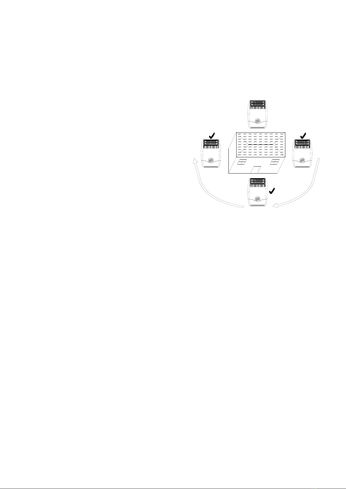
13. Upon completion of mounting the solar panel
on the wall with the tamper switch being
pressed firmly, the siren will flash about 3
seconds as an indication of normal operation.
14. After the preset alarm duration has expired the
alarm will stop and the system will
automatically reset. Subsequent activation
will again initiate an alarm condition. If an
alarm condition is initiated more than three
times then the alarm will be locked out and any
further alarm signals will be ignored until the
system is disarmed.
15. System off is to facilitate the installation of siren
& strobe without triggering an alarm condition
despite the detector or tamper switch being
triggered. Once the installation is complete
set the system to system on.
POWER-UP OF THE SIREN &
STROBE
The use of ear defenders is advisable when working
in close proximity to the Siren due to the high sound
level produced by this device if the siren is triggered.
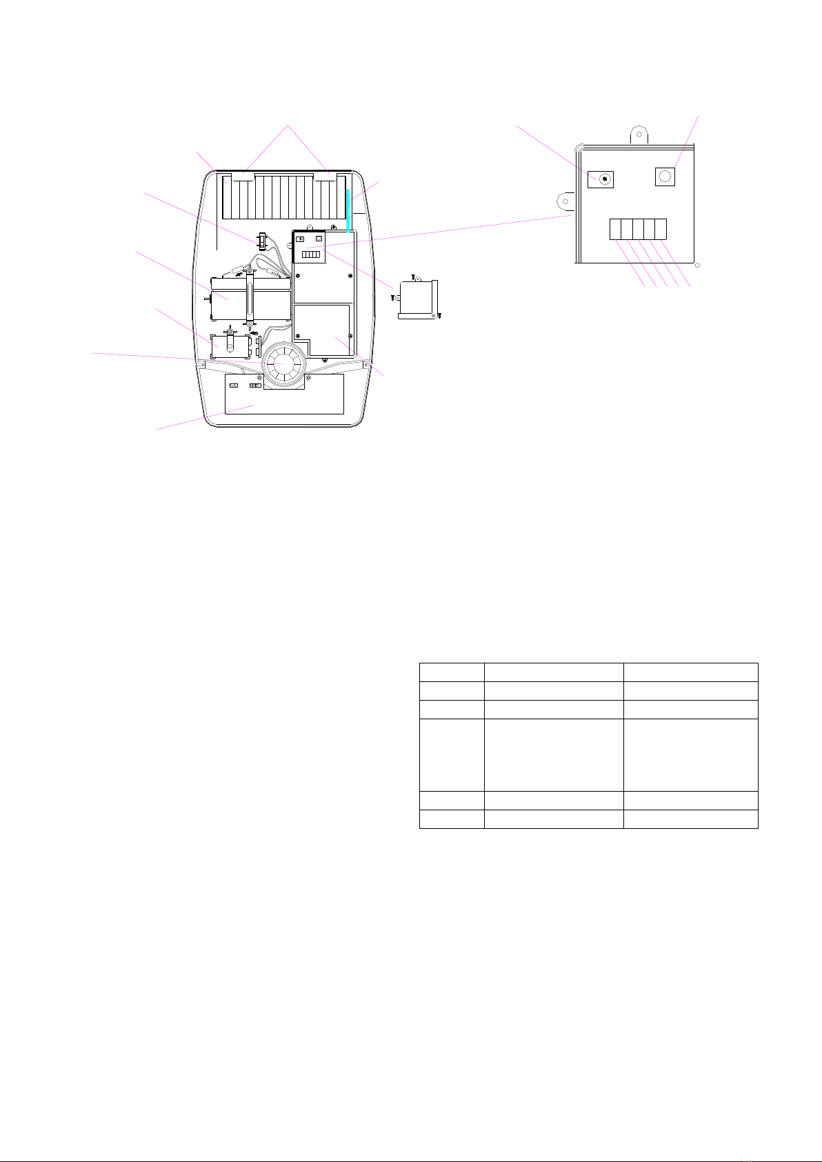
1. Connect the 9V PP3 initial power battery to the
battery clip.
Connect the rechargeable battery to the charging
leads. Connect the Red lead to the Red (+ve)
terminal and the Black lead to the Black (-ve)
terminals.
Note: Once the batteries have been connected,
the Siren will be operational and it is important
that the solar panel receives sufficient light to
maintain the battery charge. The Siren should
not be operated repeatedly during installation
and testing, as this will rapidly drain the battery.
It is recommended that the Siren be left for at
least a day in order to charge the battery before
the system is armed.
2. Press the anti-tamper switch, the LEDs will flash
together to indicate that the unit is operational.
3. Hinge the front cover locating tabs over the top
edge of the back plate and carefully push the
base of the siren cover into place. Secure the
siren cover in place by refitting the fixing screw
in the bottom edge of the cover. Do not over
tighten the screw as this could damage the
thread.
IMPORTANT: Ensure that the rear tamper switch
is closed when you fit the siren cover to the back
plate (i.e. listen for the switch to click). If the
switch does not close, this will prevent the Siren
from operating correctly. If necessary, remove
the siren cover again and adjust the screw on the
back plate tamper plunger to ensure the switch
closes when the siren is secured in position.
4. If fitted remove the protective film covering the
Solar Panel.

4
5. The fitting of the Siren is now complete.
OPERATING INSTRUCTIONS
1. The anti-jamming detection will be disabled,
though the jumper link JP1 of ANTI is fitted.
2. With siren being set at “system on”, when the
control panel enters the arm mode, it will transmit
radio signal to the siren which will generate one
beep. When it enters the disarm mode, the
siren will generate two short beeps. But when the
siren is system off, whenever the control panel
enters the arm or disarm mode, it will enable the
siren to be system on by emitting temperament
sound changing from low to high frequency and
during this audible transmission period the LED
will be on steadily.
3. Following activation into alarm condition, the
control panel will emit “Start”radio signal to the
siren to generate a full alarm. After alarm
condition has been disarmed manually or alarm
duration is expired, the control panel will send
“Stop”radio signal to the siren to stop the alarm
sound.
4. When the siren detects the activation of tamper
switch, it will send a radio signal to the control
panel to generate a full alarm condition.
5. When battery level drops, the siren will transmit a
radio signal to the control panel of which status
will be indicated on the control panel’s LED.
STATUS INDICATION
Status
LED/Strobe Indication
Audible acknowledge
Explanation
No ID code
LED flash every 2
seconds
One short beep at 10
seconds interval
Every time selecting
between siren controlled
system and control panel
based system by
disconnecting and
reconnecting the power
source or after clearing
the ID code
About to learn the ID
code by pressing the
learning button
LED Illuminates when
pressing the learning
button within 3 seconds.
LED flashes every 0.5
seconds by pressing the
learning button for more
than 3 seconds
After pressing the
learning button, one short
beep per second will be
emitted. Once 3
seconds is expired, one
long beep will be emitted.
After that, the system
enters ID code learning
mode.
Under learning the ID
code
LED flashes every 0.5
seconds repeatedly
One short beep at 3
seconds interval
Successful learning can
be expected when both
units enter the ID code
learning mode.

5
Success in learning the
ID code
LED illuminates for 0.5
seconds then
extinguishing
Beep 0.5 seconds
Failure learning the ID
code
LED flashes 3 times
rapidly
3 short beep rapidly
Clear the ID code
LED illuminates when
pressing the learning
button. LED extinguishes
after successful
clearance.
One short beep at 0.5
seconds interval, which
lasts for 6 seconds by
emitting a long beep as
successful clearance.
Within 30 seconds
period, release and press
the learning button for
more than 6 seconds, all
of the preset ID code will
be cleared.
Failure ID code clearance
LED flashes 3 times
rapidly
3 short beep rapidly
Less than 6 seconds by
pressing the learning
button for ID code
clearance
Standby
LED flashes once at 10
seconds interval
LED flashes once at 20
seconds interval as low
battery indication
System off
LED off
Temperament sound
changing from high to low
frequency
Enter system off
System on
LED keeps on. After
completion, LED off.
Temperament sound
changing from low to high
frequency
Enter system on
Delay arm mode
LED flashes during 15
seconds exit/entry delay
time
The beep speed of first
10 seconds slower while
latter 5 seconds quicker
Enter delay arm mode
Full alarm
Strobe flashes
Generate full alarm
condition
Installation is ok
Strobe flashes for 3
seconds
Press the tamper switch
once resume connect the
power source or learn the
ID code after clearing the
ID code
Low battery indication
LED flashes 20 times
rapidly

6
TROUBLESHOOTINGS
Symptom
Possible Cause
Recommendation
LED on siren not illuminating
Improper battery connection or
reverse polarity
Ensure battery connections are
good. Connect the Red lead to the
Red (+ve) terminal and the Black
lead to the Black (-ve) terminals.
Siren is out of order
Do not attempt to open the casing
as it will invalidate the warranty.
Send it for repair.
LED on siren operating, but cannot
learn the ID code or take control of
siren
Failure learning the ID code under
Siren controlled system
According to the operating
instruction, resume learning the ID
code process.
Ensure it is set at siren controlled
system
Radio channel interference, using
868.3MHz frequency
Wait for a moment to start
operating
SPECIFICATIONS
Frequency
868MHz or 923MHz Transceiver
Stand-by Current
25mA max.
Operating Current
330mA max.
Working Range
Min. 200 meter
Siren Volume
Min. 100dB/ 1 meter
*specifications are subject to change without prior notice.
A501110695R01

7
Federal Communication Commission Interference Statement
This equipment has been tested and found to comply with the limits for a Class B digital device, pursuant to Part
15 of the FCC Rules. These limits are designed to provide reasonable protection against harmful interference
in a residential installation. This equipment generates, uses and can radiate radio frequency energy and, if not
installed and used in accordance with the instructions, may cause harmful interference to radio communications.
However, there is no guarantee that interference will not occur in a particular installation. If this equipment
does cause harmful interference to radio or television reception, which can be determined by turning the
equipment off and on, the user is encouraged to try to correct the interference by one of the following measures:
- Reorient or relocate the receiving antenna.
- Increase the separation between the equipment and receiver.
- Connect the equipment into an outlet on a circuit different from that to which the receiver is connected.
- Consult the dealer or an experienced radio/TV technician for help.
This device complies with Part 15 of the FCC Rules. Operation is subject to the following two conditions: (1) This
device may not cause harmful interference, and (2) this device must accept any interference received, including
interference that may cause undesired operation.
FCC Caution: Any changes or modifications not expressly approved by the party responsible for compliance
could void the user's authority to operate this equipment.
This transmitter must not be co-located or operating in conjunction with any other antenna or transmitter.
Do not dispose of electrical appliances as unsorted municipal waste, use separate collection facilities.
Contact your local government for information regarding the collection systems available.
If electrical appliances are disposed of in landfills or dumps, hazardous substances can leak into the
groundwater and get into the food chain, damaging your health and well-being.
When replacing old appliances with new once, the retailer is legally obligated to take back your old appliance for
disposal at least for free of charge.
Table of contents
Other Challenger Security System manuals

Challenger
Challenger APFW10 User manual

Challenger
Challenger SMART FORCE User manual

Challenger
Challenger APFWKGSM User manual

Challenger
Challenger AT60 User manual

Challenger
Challenger Smart Force ASFSB User manual

Challenger
Challenger ADWC User manual

Challenger
Challenger AKWK1 User manual

Challenger
Challenger AP10LED User manual
Popular Security System manuals by other brands

U-Prox
U-Prox KEYFOB user manual

Response
Response SA1 E Installation and operating instructions

Permaconn
Permaconn DAS DL150 quick start guide

Alert Technologies
Alert Technologies EasyAssist EA-200 operating manual

NUUO
NUUO NAS NVRmini user manual

Electronic Devices Limited
Electronic Devices Limited ED510 instruction manual