Pollmeier SE Touch-to-open User manual

Instruction manual
Electric glass door lock
Touch-to-open

Operating instructions draft | 09-2017_v1
OPERATING INSTRUCTIONS
Touch to open electric glass door lock

1
Content
1 General
1.1 Performance Description as per the Building Product Ordinance
1.2 EC Declaration of Conformity
2
3
4
2 Description of the Electric Glass Door Lock
2.1 Technical Data
2.2 Function
5
6
6 Removal & Disposal 19
7 Approved Handles 19
4 Installation
4.1 Installation of the Door Hinges
4.2 Installing the Glass Door Lock
10
12
13
5 Operation and Maintenance
5.1 Troubleshooting
5.2 Emergency Release
5.3 Cleaning
5.4 Replacing the Batteries
14
15
16
17
17
3 Security
3.1 Intended Use
3.2 Unintended Use
8
8
9

2
OPERATING INSTRUCTIONS
Touch to open electric glass door lock
1 General
Please read through these operating instructions carefully before fitting or using the
product. They contain important instructions on safety which help to avoid risks, errors and
malfunctions. Keep the instructions in a safe place.
The manufacturer's warranty is voided in any case of change, extension and modification
(mechanical or electrical) of the electric glass door lock, opening the casing, or damage
caused by use of force.
The scope of supply includes:
• the electric glass door lock
• four AA Mignon alkaline batteries (1.5 V)
• three M5 x 16 countersunk screws with 3mm hexagon socket
• a design trim panel for the inside of the hinge
• a design trim panel for the outside of the hinge
• two office hinges with hinge pins
• two cover caps with clamping plates
• two frame parts
• four M6 x 20 countersunk screws with 4mm hexagon socket

3
1.1 Declaration of Performance
Declaration of Performance as per Annex III of (EU)
Ordinance no. 305/2011 (Building Product Ordinance)
1. Type:
2. Intended use:
3. Manufacturer:
4. Authorised representative:
5. System for evaluation and verification
of performance:
6. Harmonised standard:
7. Declared performance:
Electric glass door lock
Touch to open - EGS1
Motorised actuation of the latch in
single-leaf, interior glass doors
Baugruppentechnik Pollmeier GmbH,
Hövelrieger Str. 26, D-33161 Hövelhof
. / .
4
EN 14846:2008
Feature Performance
Use category:
Continuous operability and load on latch
Door mass and closing force
Suitability for use in fire protection/smoke protection doors
Security
Corrosion resistance, temperature, humidity
Protection and drill open resistance
Protection of electrical function
Protection against electrical manipulation
N/A*
S
N/A*
0
None
0
0
0
1
8. Legally binding declaration
The performance of the above mentioned product as per no. 1 complies with the declared
performance as per no. 7. The manufacturer stated above is exclusively responsible for
creating this declaration in compliance with (EU) Ordinance no. 305/2011.
* Deviates from the standard as a glass door lock
Hövelhof, 1 June 2017

4
1.2 EC Declaration of Conformity
EC Declaration of Conformity BGP 09-2017
pursuant to the EC Machinery Directive 2006/42/EC
to which this Declaration relates, complies with all applicable provisions of EC Directive
2006/42/EC – Machinery Directive.
The machine also complies with the provisions of EU Directive 2004/108/EC - Electroma-
gnetic Compatibility - and adheres to the protection objectives of the Low Voltage Directive
2006/95/EC as per Annex I, no. 1.5.1 of Machinery Directive 2006/42/EC.
The technical documentation exists in full; the operating instructions which belong to the
machine exist in the original version.
The authorised representative for compiling the technical documentation is:
Development Department, Baugruppentechnik Pollmeier GmbH, Hövelrieger Strasse 26,
33161 Hövelhof, Germany
Designation:
Type:
Serial number:
Touch to open electric
glass door lock - EGS1
See product label
Baugruppentechnik Pollmeier GmbH, Hövelrieger Str. 26, 33161 Hövelhof, Germany,
hereby declares in sole responsibility that the following machine
OPERATING INSTRUCTIONS
Touch to open electric glass door lock
Hövelhof, 1 June 2017

62
129 15
5
Outside of the hinge door lock dimensions:
Inside of the hinge door lock dimensions:
Weight:
Protection class:
Power supply:
Width: 145mm / depth: 15mm / height: 62mm
Width: 129mm / depth: 15mm / height: 62mm
500g incl. batteries / 600g without batteries
IP 20
4 x AA Mignon alkaline batteries (1.5V)
2.1 Technical Data
Electric glass door lock
Outside of the hinge
Electric glass door lock
Inside of the hinge
62
28
145 15
10,4
8,8
Battery compartment
On/off switchEmergency release
Emergency release catch

6
3 Security
3.1 Intended Use
– The lock is designed for occasional use in private interior rooms by persons who handle
the technology carefully.
– The lock is exclusively designed for installation in single-leaf glass room doors in conjuncti-
on with a wooden or aluminium frame.
– The door weight must not exceed 60 kg.
– Only use design trim panels licensed by Baugruppentechnik Pollmeier GmbH in conjuncti-
on with the electric glass door lock as the function cannot otherwise be guaranteed (see
section 7).
– The glass door lock may only be used with 8mm ESG panels.
– Only use the lock in undamaged condition without defects. Exclusively use the supplied
batteries, or equivalent (type AA 1.5 V Mignon alkaline batteries).
The A-rated emitted sound pressure level is less than or equal to 70 dB(A). There is no risk
from noise.
The maximum effective value of the weighted acceleration to which the entire body is
exposed is less than 0.5 m/s². The overall vibration value to which the upper body limbs are
exposed is less than 2.5 m/s². Thus, there is no risk due to vibration.
2.3 Function
When the glass door is closed, the latch is pulled out of the lock by the magnetic strike
plate and snaps into place in the strike plate.
When the contact surfaces are actuated, the locking part (latch) on the lock is electrically
retracted. The motor overcomes the magnetic attraction force and pulls the latch out of
the strike plate. The door can be open by pushing or pulling.
OPERATING INSTRUCTIONS
Touch to open electric glass door lock

7
Caution! Use of the electric glass door lock in doors that are located on an
identified escape and emergency route or in smoke or fire protection doors is
not intended and not permitted!
Caution! Do not use the electric glass door lock for frequently used doors in
public buildings or rooms to which access needs to be secure.
Caution! Do not use the lock in saunas or steam rooms!
Caution! One-sided handle installation is forbidden. Always fit a handle on each
side of the door!
Caution! No not insert objects into the lock's openings! Do not force open the
lock case!
Any use of the electric glass door lock other than the intended use will void your warranty.
Baugruppentechnik Pollmeier GmbH accepts no liability for any damage caused in this way.
For this reason, you must comply with the following directions:
3.2 Unintended Use

8
OPERATING INSTRUCTIONS
Touch to open electric glass door lock
4.1 Installation of the Door Hinges
1. Insert the frame parts "A" into the intended bore holes in the frame. A uniform distance of
4mm should be set between the hinge and frame part. Fix the frame parts in the door frame
hinge using the screws.
2. Insert the glass drilling protective sleeves "B" into the glass drilling holes of the door leaf.
Position clamping plate "C" and sash hinge "D" on each side above the glass drilling protec-
tive sleeves on the door leaf. The counterbores on the clamping plate must face outwardly.
Consider whether the door is mounted DIN R or DIN L. Insert the attachment screws "E"
through the clamping plate and door leaf and screw to the sash hinge. Tighten the screws
with a torque of 14Nm once you have aligned the sash hinge at a right angle to the glass
edge.
3. Lift the door leaf with sash hinges onto the frame parts mounted on the frame and fix in
place using the hinge pins "F". The groove on the hinge pin must be completely inserted at
Before fitting, check all parts for completeness and signs of damage. If you see any damage
that could impair the lock's functionality, do not fit the lock under any circumstances! Fitting
must be performed by a skilled person.
A: Frame part
B: Glass drilling protective
sleeves
C: Clamping plate
D: Sash hinge
E: Attachment screws
F: Hinge pin
G: Grub screw
H: Cover cap
A
F
G
B
E
H
C
D
the height of the grub screw in the sash hinge. Use the grub screws to secure the hinge pins
against sliding out.
4. Remove the protective films from the adhesive strips on the inside of the cover caps "H"
and stick the cover caps to the middle of the clamping plates.

9
1. Insert the frame parts "A" into the intended bore holes in the frame. A uniform distance of
4mm should be set between the hinge and frame part. Fix the frame parts in the door frame
hinge using the screws.
2. Insert the glass drilling protective sleeves "B" into the glass drilling holes of the door leaf.
Position clamping plate "C" and sash hinge "D" on each side above the glass drilling protec-
tive sleeves on the door leaf. The counterbores on the clamping plate must face outwardly.
Consider whether the door is mounted DIN R or DIN L. Insert the attachment screws "E"
through the clamping plate and door leaf and screw to the sash hinge. Tighten the screws
with a torque of 14Nm once you have aligned the sash hinge at a right angle to the glass
edge.
3. Lift the door leaf with sash hinges onto the frame parts mounted on the frame and fix in
place using the hinge pins "F". The groove on the hinge pin must be completely inserted at
the height of the grub screw in the sash hinge. Use the grub screws to secure the hinge pins
against sliding out.
4. Remove the protective films from the adhesive strips on the inside of the cover caps "H"
and stick the cover caps to the middle of the clamping plates.

10
OPERATING INSTRUCTIONS
Touch to open electric glass door lock
4.2 Installation and Commissioning of the Glass Lock
Fig. 1
1. Insert the glass lock on the inside of the
hinge with the two circular, rubber-coated
moulds into the two lock bore holes of the
whole glass door. The latch must point in the
direction of the glass edge (see Fig. 1).
2. Now guide the cable harness of the
battery compartment from the inside of the
hinge through the lock. To do so, use the
rectangular opening of the lock on the rear
lock bore hole with the adjoining cable
channel. The blend side must point in the
direction of the glass edge (see Fig. 2).
3. The battery compartment and lock can
now be loosely screwed with the M5x16
countersunk screws included in the scope of
supply as shown in Figure 3. Tighten the
screws with a torque of 0.5-1.0Nm once you
have aligned the lock with the glass edge..
Caution! The lock must be in as-delivered condition in order to install it (latch
blocked). If in doubt, detain the latch with an adhesive strip to avoid locking
yourself in!
Caution! If the lock is no longer in as-delivered condition, switch it off. Do not
restart until the handle is fitted on the lock to avoid inadvertent locking in.
Before fitting, check all parts for completeness and signs of damage. If you see any damage
that could impair the lock's functionality, do not fit the lock under any circumstances!
Fitting must be performed by a skilled person. If a component does not fit in its specified
position, you will need to modify the door or frame receptacle. No not apply force when
fitting the lock!
Before installing the electric lock, check the door to make sure that it is correctly hung and
not warped.
Fig. 2
4. Take the battery compartment connector
and insert it upright into the socket on the
electronic glass lock. The connector and
socket are coded, allowing only one oppor-
tunity to insert it (see Fig.4). If the connector
is not easy to insert, do not use force but
rotate it once on its axis and and try again.
5. Make sure that the cable harness pass
completely through the cable channel and
opening and fix it in place using an adhesive
strip.
6. Insert four new 1.5 V AA Mignon alkaline
batteries into the compartment. Pay attenti-
on to correct polarity (see Fig. 5).
7. Push the emergency release catch next to
the battery compartment in the direction of
the glass edge up to the limit stop, as shown
in Fig. 5.
8. Release the latch, which you may have
secured with adhesive tape, and then press
the on/off switch (see Fig. 6). You will hear a
long acoustic signal.
9. Put the design trim panel of the lock case
in place on the front of the lock. If the screw
heads on the back of the housing in the
keyhole-shaped openings in the lock, push
the housing in the direction of the glass
edge. It will noticeably engage!
Do exactly the same thing on the inside of
the hinge for the design trim panel of the
battery compartment.

1. Insert the glass lock on the inside of the
hinge with the two circular, rubber-coated
moulds into the two lock bore holes of the
whole glass door. The latch must point in the
direction of the glass edge (see Fig. 1).
2. Now guide the cable harness of the
battery compartment from the inside of the
hinge through the lock. To do so, use the
rectangular opening of the lock on the rear
lock bore hole with the adjoining cable
channel. The blend side must point in the
direction of the glass edge (see Fig. 2).
3. The battery compartment and lock can
now be loosely screwed with the M5x16
countersunk screws included in the scope of
supply as shown in Figure 3. Tighten the
screws with a torque of 0.5-1.0Nm once you
have aligned the lock with the glass edge..
11
Fig. 3
Fig. 4
Fig. 5
4. Take the battery compartment connector
and insert it upright into the socket on the
electronic glass lock. The connector and
socket are coded, allowing only one oppor-
tunity to insert it (see Fig.4). If the connector
is not easy to insert, do not use force but
rotate it once on its axis and and try again.
5. Make sure that the cable harness pass
completely through the cable channel and
opening and fix it in place using an adhesive
strip.
6. Insert four new 1.5 V AA Mignon alkaline
batteries into the compartment. Pay attenti-
on to correct polarity (see Fig. 5).
7. Push the emergency release catch next to
the battery compartment in the direction of
the glass edge up to the limit stop, as shown
in Fig. 5.
8. Release the latch, which you may have
secured with adhesive tape, and then press
the on/off switch (see Fig. 6). You will hear a
long acoustic signal.
9. Put the design trim panel of the lock case
in place on the front of the lock. If the screw
heads on the back of the housing in the
keyhole-shaped openings in the lock, push
the housing in the direction of the glass
edge. It will noticeably engage!
Do exactly the same thing on the inside of
the hinge for the design trim panel of the
battery compartment.
Fig. 6
6.
7.
On/off switch
IMPORTANT:
Max. 1Nm

12
OPERATING INSTRUCTIONS
Touch to open electric glass door lock
5 Operation and Maintenance
Except for the batteries, all the components of the electric mortise lock are manufactured
to be wear and maintenance free for the lock's service life. However, this assumes careful
use. Avoid the use of force which could cause damage to the lock!
Do not attempt to open the casing; there are no user-serviceable parts on the inside!
An acoustic signal will indicate any need to intervene during operation or installation. The
following overviews show the various audible signals and their meanings.
All audible signals during operation
Double beep/5 min. Replace batteries
RequestOperating stateType of audible signal
Batteries exhausted
All audible signals during installation
One long beep Device switching on
RequestOperating stateType of audible signal
Beep sequence: short, short, long −
−
Device switching off

13
5.1 Troubleshooting
If the lock unexpectedly fails to work, first check the following points:
Malfunction Possible cause Possible solution
Lock beeps twice
periodically approx. every
5 min. and the latch
remains in the lock
Batteries exhausted Replace batteries (see 5.4)
Noise on opening/closing Foreign body on latch or in strike
plate
Clean, carefully remove objects (see 5.3)
Lock fails to open or close
correctly
Latch bent or broken due to use
of force
Replace lock
Lock fails to close Batteries exhausted Replace batteries (see 5.4)
Lock slow to open The latch is not centred with
respect to the backlining.
Lock not opening Internal, transient malfunction Remove design trim panel, unlock the latch
mechanically using the emergency release
catch, press the on/off switch (this reboots the
lock), install the design trim panel
The design trim panels
cannot be connected!
The round head screws have
been screwed in too far
Loosen the four round head screws by a
quarter rotation on the inside of the design
trim panels in order to reduce the contact
pressure!
Press in the door seals
Adjust the door hinges
Batteries inserted incorrectly
(wrong polarity)
Insert batteries as specified
Lock not switched on Press on/off switch to activate the lock. (see 4.2)
Lock not designed for glass
thickness
Only use panels with 8mm glass thickness
Emergency release catch in
wrong position
Push emergency release up to the limit stop in
the direction of the glass edge und unlock
again
Electronics problem in
lock/overload/motor defective
Replace lock
Lock not correctly seated on the
door leaf
Reposition & fasten lock
If it proves impossible to resolve the problem, please remove the lock and contact Baugrup-
pentechnik Pollmeier GmbH. Expert staff is available to help you.

14
OPERATING INSTRUCTIONS
Touch to open electric glass door lock
5.2 Emergency Release
Emergency door release is not necessary in normal operation and with proper use. Safety
mechanisms have been installed in the lock that provide for automatic unlocking if normal
operation is compromised. You always have the following options to unlock the door to
guarantee that the door can always be opened.
Push the design trim panel (lock cover) in the direction of the door leaf and full them
forwards over the lock case. The extended latch can now be pushed into the lock using the
catch (see Fig. 7). Only release the latch once you have opened the door. Now start the lock
again and fit the design trim panel as described under section 4.1, step 9.
Fig. 7 Fig. 8
Emergency release on the outside of the hinge
Push the design trim panel (battery compartment cover) in the direction of the door leaf
and full them forwards over the battery compartment. The extended latch can now be
pushed into the lock for the emergency release using the catch (see Fig. 8). Only release
the catch once you have opened the door. Now start the lock again and push the
emergency release catch back completely in the direction of the glass edge. Fit the design
trim panel as described under section 4.1, step 9.
Emergency release on the inside of the hinge
the front of the lock. If the screw heads on
the back of the trim panel engage in the
keyhole-shaped openings in the lock, push
the design trim panel in the direction of the
glass edge and it will noticeably engage (see
Fig. 12).
Do exactly the same thing on the inside of
the hinge for the design trim panel of the
battery compartment.
1. Start by opening the door. Push both design
trim panels in the direction of the door leaf
and full them forwards over the battery
compartment and the lock case (see Fig. 9).
2. Dispose of the old batteries responsibly and
insert four new 1.5 V AA Mignon alkaline
batteries into the compartment. Pay attention
to correct polarity (see Fig. 10)
3. Press the on/off switch (see Fig. 11). A single
acoustic signal indicates that the lock is
switched on again.
4. Then put the design trim panel in place on

the front of the lock. If the screw heads on
the back of the trim panel engage in the
keyhole-shaped openings in the lock, push
the design trim panel in the direction of the
glass edge and it will noticeably engage (see
Fig. 12).
Do exactly the same thing on the inside of
the hinge for the design trim panel of the
battery compartment.
15
5.3 Cleaning
Due to protected installation and the wear-free design, cleaning is only rarely required. To
clean, wipe the lock and the strike plate with a dry cloth. Do not use chemicals, cleaning
agents, solvents or objects for mechanical cleaning!
Carefully remove any metal chips on the latch or strike plate with a soft cloth or a brush.
5.4 Replacing the Batteries
When the batteries are exhausted, the lock outputs an audible signal, retracts the latch and
changes to lock mode to avoid blocking the door. This state is indicated by a double peep,
which the lock emits periodically at an interval of 5 min. Follow these steps to replace the
batteries:
Caution! To replace the batteries, the lock must be switched off or in lock mode
(latch retracted) in case of weak batteries. If in doubt, detain the latch with an
adhesive strip to avoid locking yourself in!
Caution! Never insert an empty battery compartment into the lock. On closing
the door, the lock would immediately engage; in this case, opening is only
possible via emergency release.
Fig. 9
Fig. 10
1. Start by opening the door. Push both design
trim panels in the direction of the door leaf
and full them forwards over the battery
compartment and the lock case (see Fig. 9).
2. Dispose of the old batteries responsibly and
insert four new 1.5 V AA Mignon alkaline
batteries into the compartment. Pay attention
to correct polarity (see Fig. 10)
3. Press the on/off switch (see Fig. 11). A single
acoustic signal indicates that the lock is
switched on again.
4. Then put the design trim panel in place on

16
OPERATING INSTRUCTIONS
Touch to open electric glass door lock
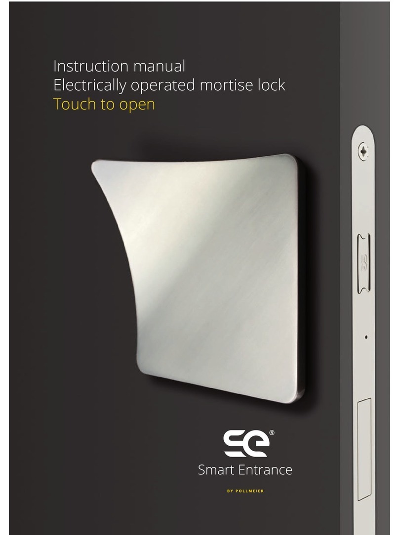
Fig. 12
Fig. 11
To keep the electric mortise lock in perfect working condition at all times, only SE-certified
handles are approved for the lock. When purchasing your handle, please watch out for the
SE mark, which ensures compatibility with the Smart Entrance technology.
6 Removal and Disposal
To remove the door, remove covers, pull the battery compartment connector out of the lock
and remove the screws from the battery compartment. You can now remove the parts from
the door. Then remove the batteries as described in section 4.2.
Caution! Never store the lock for an extended period of time with the batteries
fitted. Leaking batteries could damage the electronics!
Do not dispose of the batteries or lock as domestic waste. Instead hand them in
at an appropriate collection point (retailer, recycling depot or mobile recycling
vehicle).
7 Approved Handles
the front of the lock. If the screw heads on
the back of the trim panel engage in the
keyhole-shaped openings in the lock, push
the design trim panel in the direction of the
glass edge and it will noticeably engage (see
Fig. 12).
Do exactly the same thing on the inside of
the hinge for the design trim panel of the
battery compartment.
1. Start by opening the door. Push both design
trim panels in the direction of the door leaf
and full them forwards over the battery
compartment and the lock case (see Fig. 9).
2. Dispose of the old batteries responsibly and
insert four new 1.5 V AA Mignon alkaline
batteries into the compartment. Pay attention
to correct polarity (see Fig. 10)
3. Press the on/off switch (see Fig. 11). A single
acoustic signal indicates that the lock is
switched on again.
4. Then put the design trim panel in place on

17
the front of the lock. If the screw heads on
the back of the trim panel engage in the
keyhole-shaped openings in the lock, push
the design trim panel in the direction of the
glass edge and it will noticeably engage (see
Fig. 12).
Do exactly the same thing on the inside of
the hinge for the design trim panel of the
battery compartment.
1. Start by opening the door. Push both design
trim panels in the direction of the door leaf
and full them forwards over the battery
compartment and the lock case (see Fig. 9).
2. Dispose of the old batteries responsibly and
insert four new 1.5 V AA Mignon alkaline
batteries into the compartment. Pay attention
to correct polarity (see Fig. 10)
3. Press the on/off switch (see Fig. 11). A single
acoustic signal indicates that the lock is
switched on again.
4. Then put the design trim panel in place on

14
Other manuals for SE Touch-to-open
1
This manual suits for next models
1
Table of contents
Other Pollmeier Security System manuals
Popular Security System manuals by other brands

Rear view safety
Rear view safety MobileMule 2100 manual

M-system
M-system KSL-x5 instruction manual

Fortinet
Fortinet FortiManager-400A quick start guide

YOKOGAWA
YOKOGAWA VJRK user manual

HeroSpeed
HeroSpeed PoE NVR Kits quick start guide

Sirena
Sirena OVOLUX R Series INSTALLATION AND APPLICATION INSTRUCTIONS